Frame Replacement Convertible
Special Tools
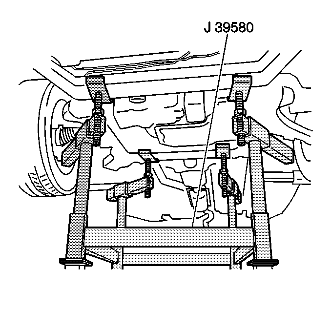
J 39580 Engine Support Stand
Removal Procedure
- Support the radiator and condenser from above.
- Raise the vehicle on a hoist. Refer to Lifting and Jacking the Vehicle.
- Remove the tire and wheel assemblies. Refer to Tire and Wheel Removal and Installation.
- Remove the engine splash shields. Refer to Engine Splash Shield Replacement - Left Side and Engine Splash Shield Replacement - Right Side.
- Remove the radiator air lower baffle. Refer to Radiator Air Lower Baffle and Deflector Replacement.
- Disconnect the antilock brake system (ABS) sensor from the wheel speed sensor and frame.
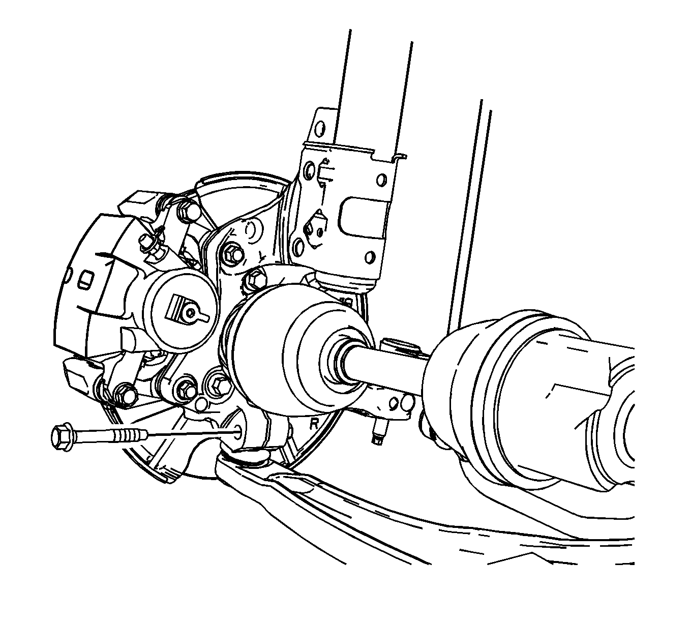
- Remove the lower ball joints from the steering knuckles.
- Remove the tie rod ends from the steering knuckles. Refer to Steering Linkage Outer Tie Rod Replacement.
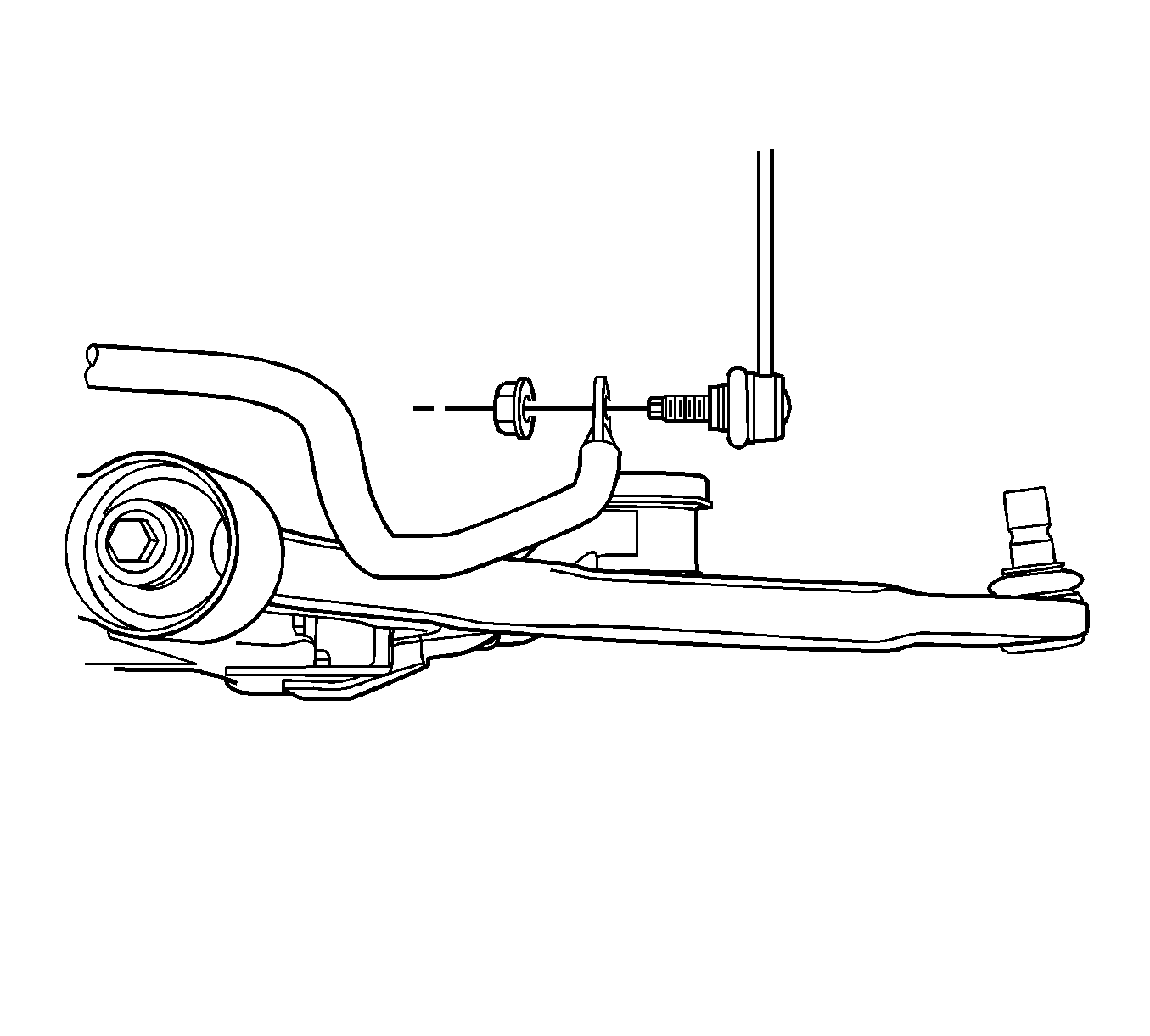
- Remove both stabilizer links from the stabilizer bar.
- Remove the power steering gear mounting bolts and secure the gear out of the way using mechanics wire or equivalent, being sure not to overextend the intermediate shaft. Refer to Steering Gear Replacement.
- Remove the engine mount nuts from the frame. Refer to Engine Mount Replacement for the 3.5L engine or Engine Mount Replacement for the 3.9L engine.
- Remove the front transmission mount bolt from the frame. Refer to Transmission Front Mount Replacement for the F40 transmission, Transmission Front Mount Replacementfor the 4T45-E transmission, or Transmission Front Mount Replacement for the 4T65-E transmission.
- Remove the left transmission mount nuts from the frame. Refer to Transmission Mount Replacement - Left Side for the F40 transmission or Transmission Mount Replacement - Left Side for the 4T65-E transmission.
- Remove the rear transmission mount bracket nuts from the frame. Refer to Transmission Rear Mount Bracket Replacement for the F40 transmission, Transmission Rear Mount Replacement for the 4T45-E transmission, or Transmission Rear Mount Bracket Replacement for the 4T65-E transmission.
- Remove the brake lines from the retainers on the frame.
- Remove the catalytic converter. Refer to Catalytic Converter Replacement - Left Side or Catalytic Converter Replacement - Right Side.
- Remove the power steering mounting bolts and secure the gear out of the way using mechanic's wire or equivalent, being sure not to overextend the intermediate shaft. Refer to Steering Gear Replacement.
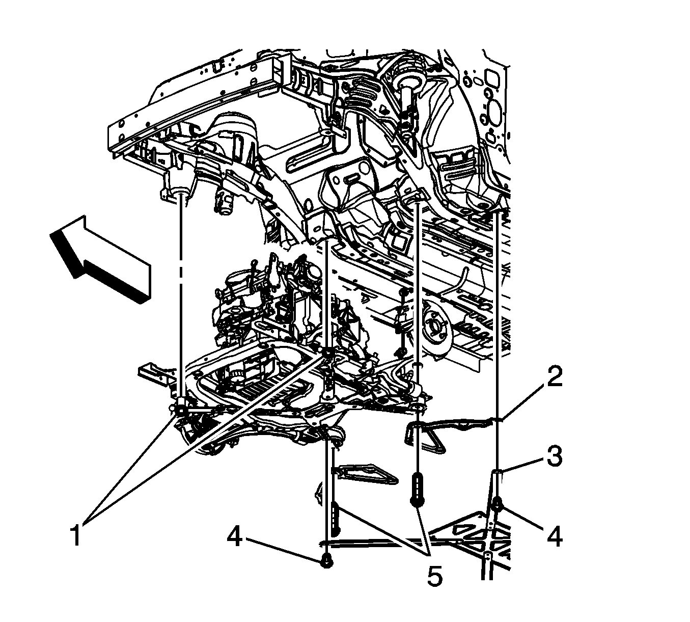
- Lower the vehicle until the frame contacts the J 39580 .
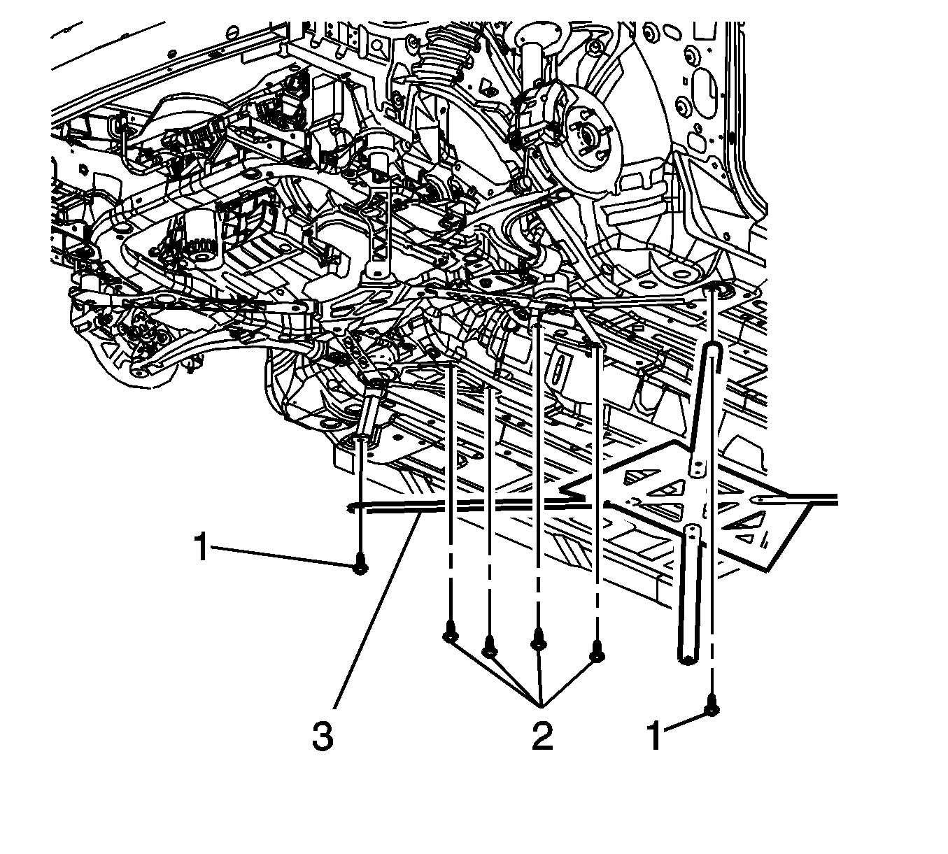
- Remove the frame reinforcement bolts (2) and frame brace bolts (1).
- Remove the front frame bolts (1).
- Remove the rear frame bolts (5).
- Remove the frame reinforcements (2).
- Raise the vehicle off of the frame.
- Remove the following components if replacing the frame:
| • | The lower control arms--Refer to Lower Control Arm Replacement. |
| • | The stabilizer shaft--Refer to Stabilizer Shaft Replacement. |
Installation Procedure
- Install the following components on the suspension crossmember if removed:
- Lower the vehicle on to the frame.
- Install the power steering gear mounting bolts. Refer to Steering Gear Replacement.
- Install the frame reinforcements (2).
- Install the rear frame bolts (5).
- Install the front frame bolts (1).
- Install the frame reinforcement bolts (2) and frame brace bolts (1).
- Raise the vehicle.
- Install the brake lines to the retainers on the frame.
- Install the rear transmission mount bracket nuts. Refer to Transmission Rear Mount Bracket Replacement for the F40 transmission, Transmission Rear Mount Replacementfor the 4T45-E transmission, or Transmission Rear Mount Bracket Replacement for the 4T65-E transmission.
- Install the left transmission mount nuts to the frame. Refer to Transmission Mount Replacement - Left Side for the F40 transmission or Transmission Mount Replacement - Left Side for the 4T65-E transmission.
- Install the front transmission mount bracket bolt. Refer to Transmission Front Mount Replacement for the F40 transmission, Transmission Front Mount Replacement for the 4T45-E transmission, or Transmission Front Mount Replacement for the 4T65-E transmission.
- Install the engine mount nuts to the frame. Refer to Engine Mount Replacement for the 3.5L engine or Engine Mount Replacement for the 3.9L engine.
- Install the power steering gear mounting bolts. Refer to Steering Gear Replacement.
- Install both stabilizer links to the stabilizer bar.
- Install the tie rod ends to the steering knuckles. Refer to Steering Linkage Outer Tie Rod Replacement.
- Install the lower ball joints to the steering knuckles.
- Install the rear catalytic converter. Refer to Catalytic Converter Replacement - Left Side or Catalytic Converter Replacement - Right Side.
- Connect the ABS sensor to the wheel speed sensor and frame.
- Install the radiator air lower baffle. Refer to Radiator Air Lower Baffle and Deflector Replacement.
- Install the engine splash shields. Refer to Engine Splash Shield Replacement - Left Side and Engine Splash Shield Replacement - Right Side.
- Install the tire and wheel assemblies. Refer to Tire and Wheel Removal and Installation.
- Remove the engine support fixture.
- Bleed the power steering system. Refer to Power Steering System Bleeding.
| • | The stabilizer shaft--Refer to Stabilizer Shaft Replacement. |
| • | The lower control arms--Refer to Lower Control Arm Replacement. |

Notice: Refer to Fastener Notice in the Preface section.
Tighten
Tighten the bolts to 100 N·m (74 lb ft) plus 180 degree rotation.
Tighten
Tighten the bolts to 100 N·m (74 lb ft) plus 180 degree rotation.

Tighten
Tighten the bolts to 50 N·m (37 lb ft).

Tighten
Tighten the stabilizer link nut to 65 N·m (48 lb ft) plus 180 degree rotation.

Tighten
Tighten the ball stud to steering knuckle pinch nut to 50 N·m (37 lb ft). Reverse the nut ¾ of a turn. Tighten to 50 N·m (37 lb ft) plus 60 degrees.
Frame Replacement Coupe 2.4L
Special Tools
J 39580 Engine Support Stand
Removal Procedure
- Install the engine support fixture. Refer to Engine Support Fixture .
- Raise the vehicle on a hoist. Refer to Lifting and Jacking the Vehicle .
- Remove the tire and wheel assemblies. Refer to Tire and Wheel Removal and Installation .
- Remove the engine splash shields. Refer to Engine Splash Shield Replacement - Left Side and Engine Splash Shield Replacement - Right Side .
- Remove the radiator air lower baffle. Refer to Radiator Air Lower Baffle and Deflector Replacement .
- Disconnect the antilock brake system (ABS) sensor from the wheel speed sensor and frame.
- Remove the lower ball joints from the steering knuckles.
- Remove the tie rod ends from the steering knuckles. Refer to Steering Linkage Outer Tie Rod Replacement .
- Remove both stabilizer links from the stabilizer bar. Refer to Stabilizer Shaft Link Replacement .
- Remove the power steering gear mounting bolts and secure the gear out of the way using mechanic wire or equivalent, being sure not to overextend the intermediate shaft. Refer to Steering Gear Replacement .
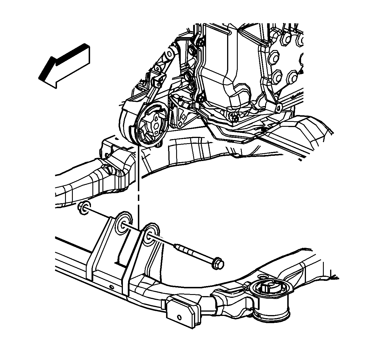
- Remove the front transmission mount bolt from the frame. Refer to Transmission Front Mount Replacement .
- Remove the left transmission mount nuts from the frame. Refer to Transmission Mount Replacement - Left Side .
- Remove the rear transmission mount bracket nuts from the frame. Refer to Transmission Rear Mount Replacement .
- Remove the brake lines from the retainers on the frame.
- Lower the vehicle until the frame contacts the J 39580 .
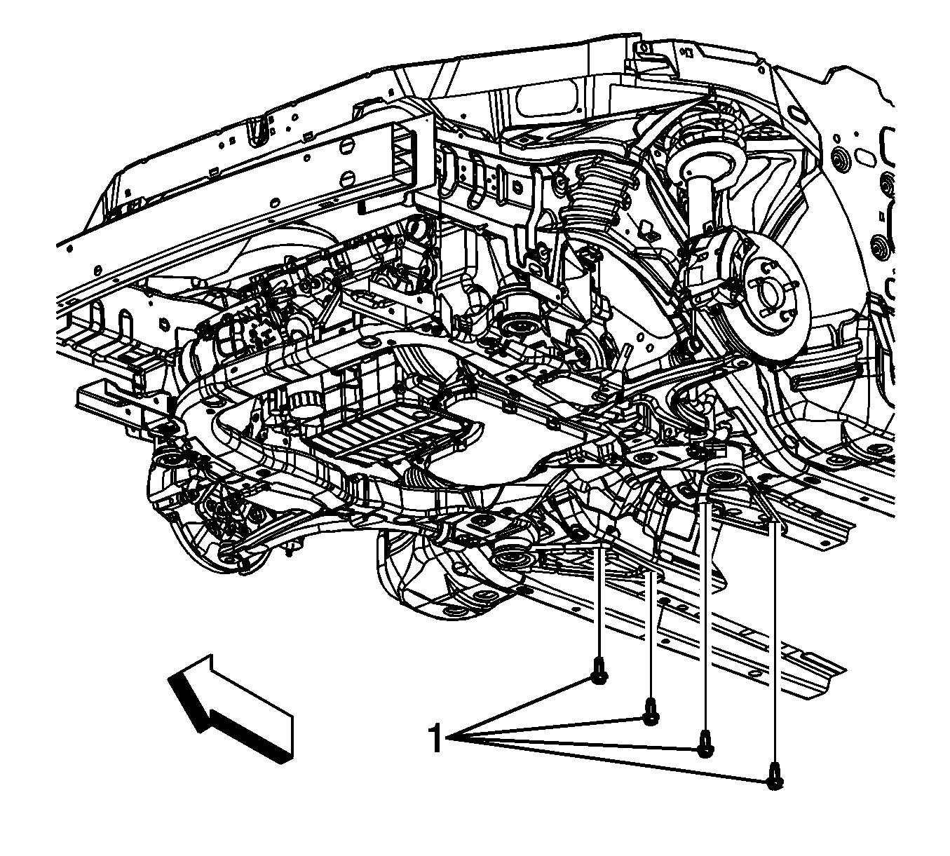
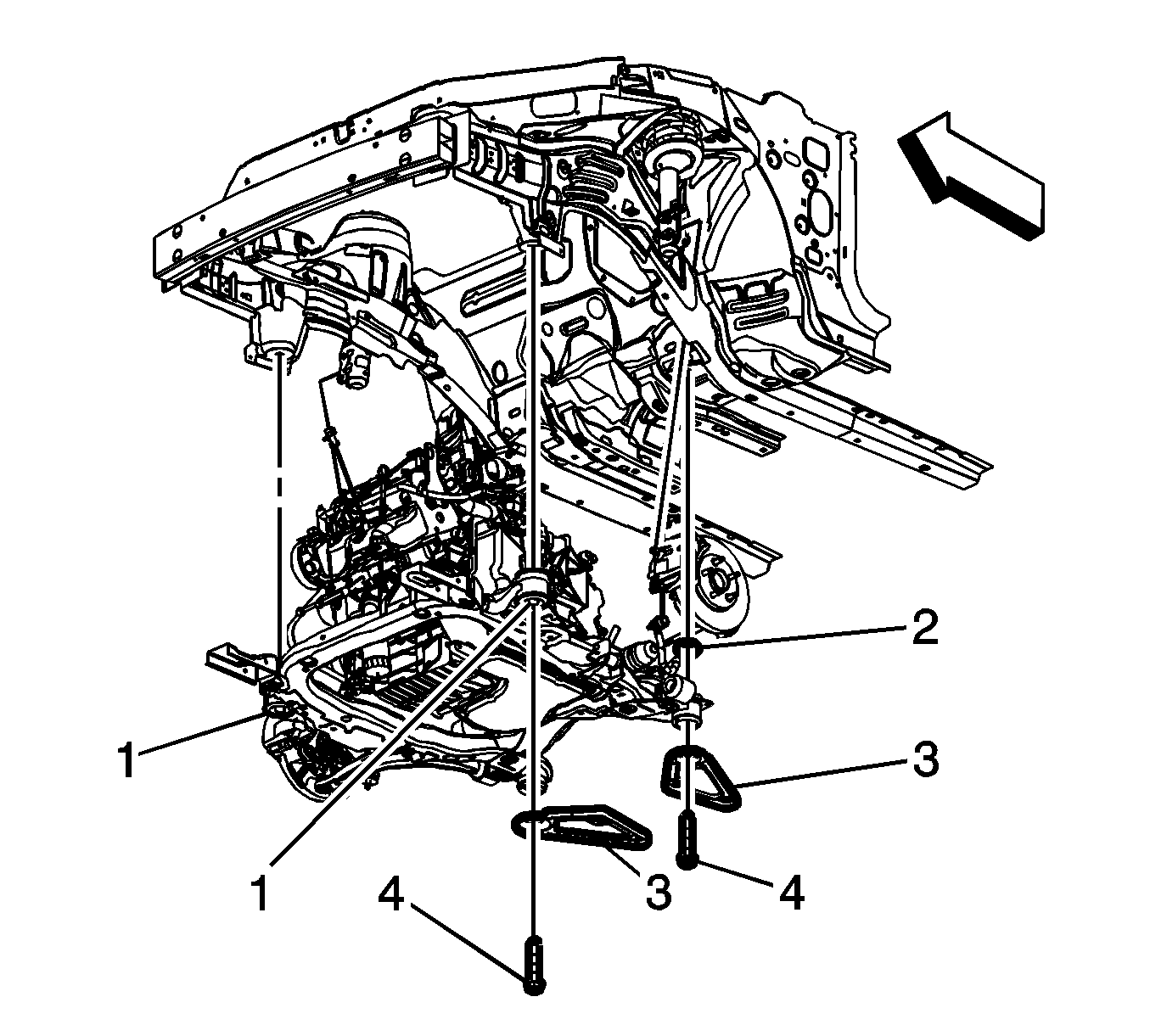
- Remove the reinforcement bolts (1).
- Remove the front frame bolts (1).
- Remove the rear frame bolts (4).
- Remove the frame reinforcements (3).
- Raise the vehicle off of the frame.
- Remove the following components if replacing the frame:


| • | The lower control arms--Refer to Lower Control Arm Replacement . |
| • | The stabilizer shaft--Refer to Stabilizer Shaft Replacement . |
Installation Procedure
- Install the following components on the suspension crossmember if removed:
- Lower the vehicle on to the frame.
- Install the frame reinforcements (3).
- Install the rear frame bolts (4).
- Install the front frame bolts (1).
- Install the reinforcement bolts (1).
- Raise the vehicle.
- Install the brake lines to the retainers on the frame.
- Install the rear transmission mount bracket nuts. Refer to Transmission Rear Mount Replacement .
- Install the left transmission mount nuts to the frame. Refer to Transmission Mount Replacement - Left Side .
- Install the front transmission mount bracket bolt. Refer to Transmission Front Mount Replacement .
- Install the power steering gear mounting bolts. Refer to Steering Gear Replacement .
- Install both stabilizer links to the stabilizer bar.
- Install the tie rod ends to the steering knuckles. Refer to Steering Linkage Outer Tie Rod Replacement .
- Install the lower ball joints to the steering knuckles.
- Connect the ABS sensor to the wheel speed sensor and frame.
- Install the radiator air lower baffle. Refer to Radiator Air Lower Baffle and Deflector Replacement .
- Install the engine splash shields. Refer to Engine Splash Shield Replacement - Left Side and Engine Splash Shield Replacement - Right Side .
- Install the tire and wheel assemblies. Refer to Tire and Wheel Removal and Installation .
- Remove the engine support fixture.
- Bleed the power steering system. Refer to Power Steering System Bleeding .
| • | The stabilizer shaft--Refer to Stabilizer Shaft Replacement . |
| • |
| • | The lower control arms--Refer to Lower Control Arm Replacement . |

Notice: Refer to Fastener Notice in the Preface section.
Tighten
Tighten the bolts to 100 N·m (74 lb ft) plus 180 degree rotation.
Tighten
Tighten the bolts to 100 N·m (74 lb ft) plus 180 degree rotation.

Tighten
Tighten the bolts to 50 N·m (37 lb ft).

Tighten
Tighten the stabilizer link nut to 65 N·m (48 lb ft).

Tighten
Tighten the ball stud to steering knuckle pinch nut to 50 N·m (37 lb ft). Reverse the nut ¾ of a turn. Tighten to 50 N·m (37 lb ft) plus 60 degrees.
Frame Replacement Coupe 3.5L, 3.9L
Special Tools
J 39580 Engine Support Stand
Removal Procedure
- Install the engine support fixture. Refer to Engine Support Fixture for the 3.5L engine or Engine Support Fixture for the 3.9L engine.
- Raise the vehicle on a hoist. Refer to Lifting and Jacking the Vehicle .
- Remove the tire and wheel assemblies. Refer to Tire and Wheel Removal and Installation .
- Remove the engine splash shields. Refer to Engine Splash Shield Replacement - Left Side and Engine Splash Shield Replacement - Right Side .
- Remove the radiator air lower baffle. Refer to Radiator Air Lower Baffle and Deflector Replacement .
- Disconnect the antilock brake system (ABS) sensor from the wheel speed sensor and frame.
- Remove the lower ball joints from the steering knuckles. Refer to Lower Control Arm Replacement .
- Remove the tie rod ends from the steering knuckles. Refer to Steering Linkage Outer Tie Rod Replacement .
- Remove both stabilizer links from the stabilizer bar.
- Remove the power steering gear mounting bolts and secure the gear out of the way using mechanics wire or equivalent, being sure not to overextend the intermediate shaft. Refer to Steering Gear Replacement .
- Remove the engine mount nuts from the frame. Refer to Engine Mount Replacement for the 3.5L engine or Engine Mount Replacement for the 3.9L engine.
- Remove the front transmission mount bolt from the frame. Refer to Transmission Front Mount Replacement for the F40 transmission, Transmission Front Mount Replacement for the 4T45-E transmission, or Transmission Front Mount Replacement for the 4T65-E transmission.
- Remove the left transmission mount nuts from the frame. Refer to Transmission Mount Replacement - Left Side for the F40 transmission, Transmission Mount Replacement - Left Side for the 4T45-E transmission, or Transmission Mount Replacement - Left Side for the 4T65-E transmission.
- Remove the rear transmission mount bracket nuts from the frame. Refer to Transmission Rear Mount Bracket Replacement for the F40 transmission, Transmission Rear Mount Replacement for the 4T45-E transmission, or Transmission Rear Mount Bracket Replacement for the 4T65-E transmission.
- Remove the brake lines from the retainers on the frame.
- Lower the vehicle until the frame contacts the J 39580 .
- Remove the reinforcement bolts (1).
- Remove the front frame bolts (1).
- Remove the rear frame bolts (4).
- Remove the frame reinforcements (3).
- Raise the vehicle off of the frame.
- Remove the following components if replacing the frame:


| • | The lower control arms--Refer to Lower Control Arm Replacement . |
| • |
| • | The stabilizer shaft--Refer to Stabilizer Shaft Replacement . |
| • |
Installation Procedure
- Install the following components on the suspension crossmember if removed:
- Lower the vehicle on to the frame.
- Install the frame reinforcements (3).
- Install the rear frame bolts (4).
- Install the front frame bolts (1).
- Install the reinforcement bolts (1).
- Raise the vehicle.
- Install the brake lines to the retainers on the frame.
- Install the rear transmission mount bracket nuts. Refer to Transmission Rear Mount Bracket Replacement for the F40 transmission, Transmission Rear Mount Replacement for the 4T45-E transmission, or Transmission Rear Mount Bracket Replacement for the 4T65-E transmission.
- Install the left transmission mount nuts to the frame. Refer to Transmission Mount Replacement - Left Side for the F40 transmission, Transmission Mount Replacement - Left Side for the 4T45-E transmission, or Transmission Mount Replacement - Left Side for the 4T65-E transmission.
- Install the front transmission mount bracket bolt. Refer to Transmission Front Mount Replacement for the F40 transmission, Transmission Front Mount Replacement for the 4T45-E transmission, or Transmission Front Mount Replacement for the 4T65-E transmission.
- Install the engine mount nuts to the frame. Refer to Engine Mount Replacement for the 3.5L engine or Engine Mount Replacement for the 3.9L engine.
- Install the power steering gear mounting bolts. Refer to Steering Gear Replacement .
- Install both stabilizer links to the stabilizer bar.
- Install the tie rod ends to the steering knuckles. Refer to Steering Linkage Outer Tie Rod Replacement .
- Install the lower ball joints to the steering knuckles.
- Connect the ABS sensor to the wheel speed sensor and frame.
- Install the radiator air lower baffle. Refer to Radiator Air Lower Baffle and Deflector Replacement .
- Install the engine splash shields. Refer to Engine Splash Shield Replacement - Left Side and Engine Splash Shield Replacement - Right Side .
- Install the tire and wheel assemblies. Refer to Tire and Wheel Removal and Installation .
- Remove the engine support fixture.
- Bleed the power steering system. Refer to Power Steering System Bleeding .
| • | The stabilizer shaft--Refer to Stabilizer Shaft Replacement . |
| • | The lower control arms--Refer to Lower Control Arm Replacement . |

Notice: Refer to Fastener Notice in the Preface section.
Tighten
Tighten the bolts to 100 N·m (74 lb ft) plus 180 degree rotation.
Tighten
Tighten the bolts to 100 N·m (74 lb ft) plus 180 degree rotation.

Tighten
Tighten the bolts to 50 N·m (37 lb ft).
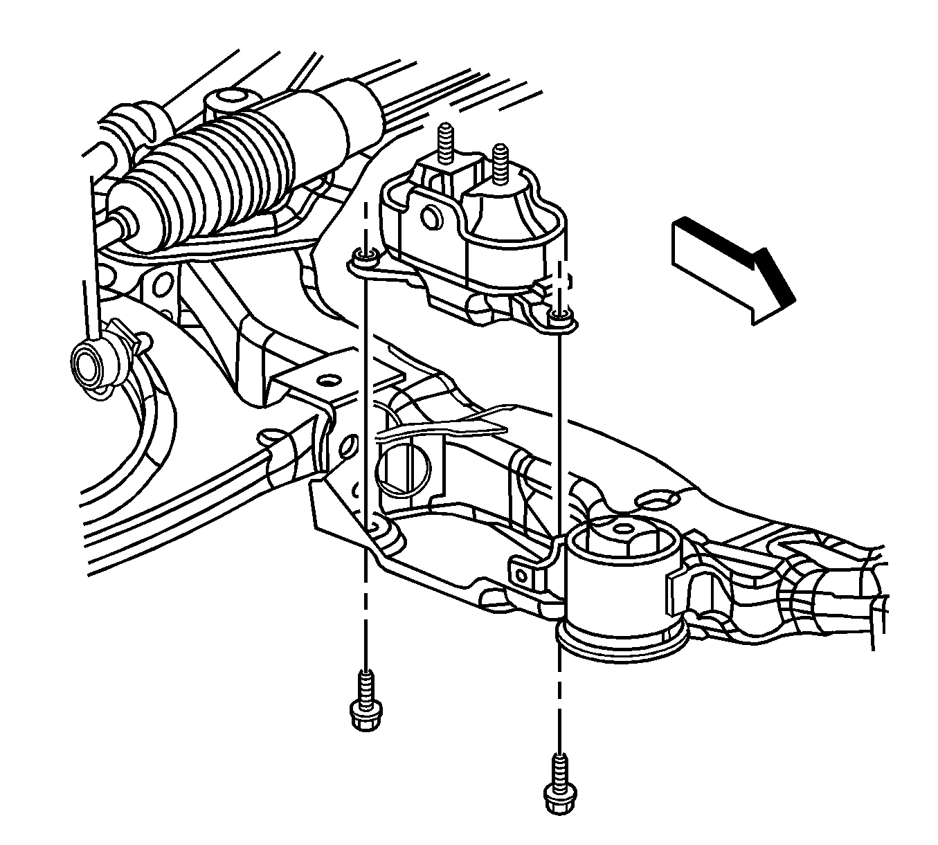

Tighten
Tighten the stabilizer link nut to 65 N·m (48 lb ft) plus 180 degree rotation.

Tighten
Tighten the ball stud to steering knuckle pinch nut to 50 N·m (37 lb ft). Reverse the nut ¾ of a turn. Tighten to 50 N·m (37 lb ft) plus 60 degrees.
Frame Replacement 3.6L
Special Tools
J 39580 Engine Support Stand
Removal Procedure
- Install the engine support fixture. Refer to Engine Support Fixture .
- Support the radiator and condenser from above.
- Raise the vehicle on a hoist. Refer to Lifting and Jacking the Vehicle .
- Remove the tire and wheel assemblies. Refer to Tire and Wheel Removal and Installation .
- Remove the radiator air lower baffle. Refer to Radiator Air Lower Baffle and Deflector Replacement .
- Remove the engine splash shields. Refer to Engine Splash Shield Replacement - Left Side and Engine Splash Shield Replacement - Right Side .
- Remove the lower ball joints from the steering knuckles. Refer to Lower Control Arm Replacement .
- Remove the tie rod ends from the steering knuckles. Refer to Steering Linkage Outer Tie Rod Replacement .
- Remove both stabilizer links from the stabilizer bar. Refer to Stabilizer Shaft Link Replacement .
- Remove the power steering gear mounting bolts and secure the gear out of the way using mechanic's wire or equivalent, being sure not to overextend the intermediate shaft. Refer to Steering Gear Replacement .
- Remove the engine mount fasteners from the frame. Refer to Engine Mount Replacement - Right Side .
- Remove the front transmission mount bolt from the frame. Refer to Transmission Front Mount Replacement .
- Remove the left transmission mount fasteners from the frame. Refer to Transmission Mount Replacement - Left Side .
- Remove the rear transmission mount bracket fasteners from the frame. Refer to Transmission Rear Mount Replacement .
- Remove the brake lines from the retainers on the frame.
- Remove the power steering outlet pipe/hose from the frame. Refer to Power Steering Gear Outlet Pipe/Hose Replacement .
- Remove the rear catalytic converter. Refer to Catalytic Converter Replacement - Left Side or Catalytic Converter Replacement - Right Side .
- Lower the vehicle until the frame contacts the J 39580 .
- Remove the reinforcement bolts (1).
- Remove the front frame bolts (1).
- Remove the rear frame bolts (4).
- Remove the frame reinforcements (3).
- Raise the vehicle off of the frame.
- Remove the following components if replacing the frame:


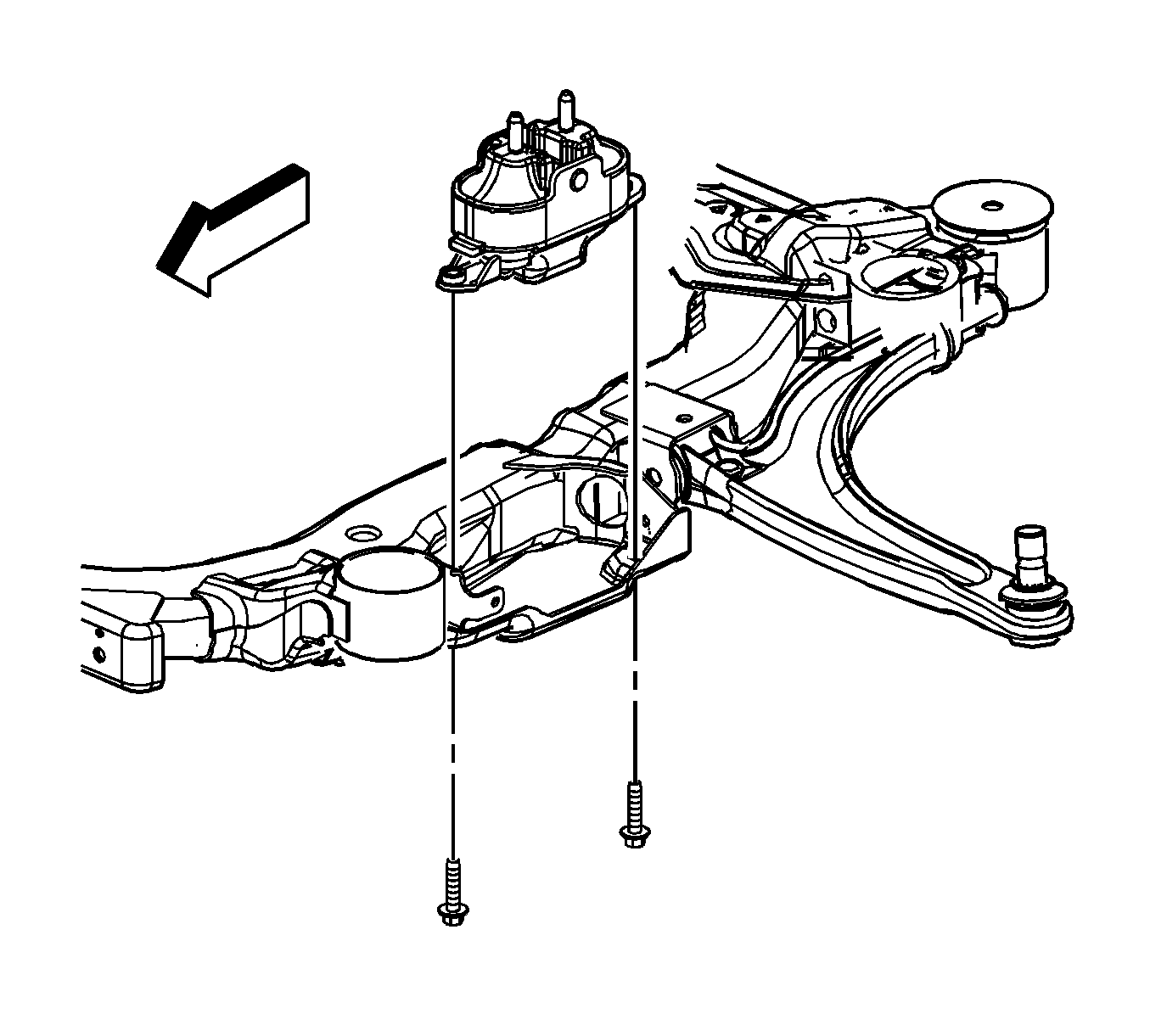
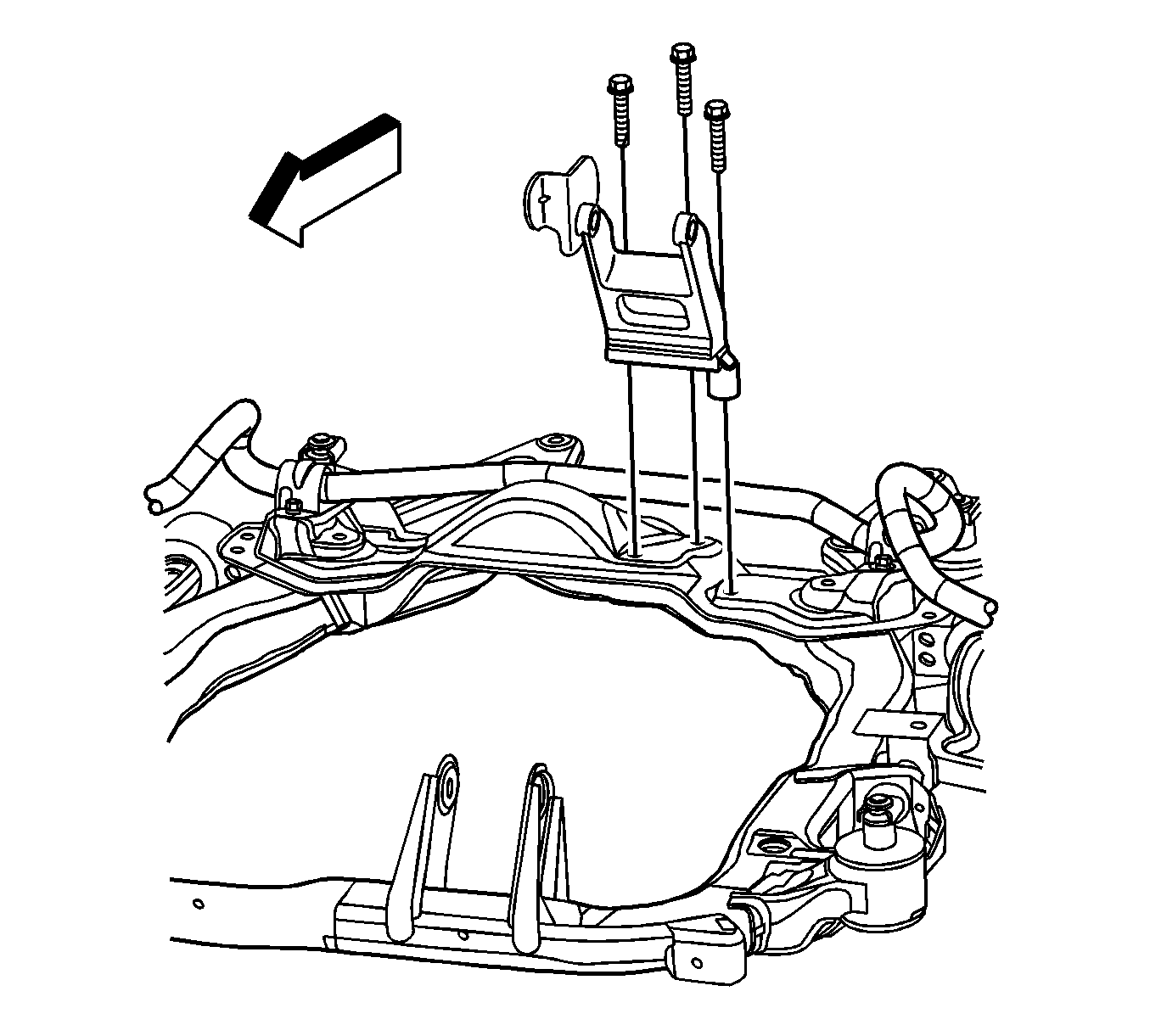


| • | The lower control arms--Refer to Lower Control Arm Replacement . |
| • |
| • | The stabilizer shaft--Refer to Stabilizer Shaft Replacement . |
| • |
Installation Procedure
- Install the following components on the suspension crossmember if removed:
- Lower the vehicle on to the frame.
- Install the frame reinforcements (3).
- Install the front frame bolts. Hand tighten ONLY.
- Install the reinforcement bolts. Hand tighten ONLY.
- Tighten the rear frame bolts (4).
- Tighten the front frame bolts (1) to specifications.
- Install the reinforcement bolts (1).
- Raise the vehicle.
- Install the power steering outlet pipe/hose to the frame. Refer to Power Steering Gear Outlet Pipe/Hose Replacement .
- Install the brake lines to the retainers on the frame.
- Install the rear transmission mount bracket fasteners. Refer to Transmission Rear Mount Replacement .
- Install the left transmission mount fasteners to the frame. Refer to Transmission Mount Replacement - Left Side .
- Install the front transmission mount bracket bolt. Refer to Transmission Front Mount Replacement .
- Install the engine mount fasteners to the frame. Refer to Engine Mount Replacement - Right Side .
- Install the power steering gear mounting fasteners. Refer to Steering Gear Replacement .
- Install both stabilizer links to the stabilizer bar.
- Install the tie rod ends to the steering knuckles. Refer to Steering Linkage Outer Tie Rod Replacement .
- Install the lower ball joints to the steering knuckles.
- Reverse the nut ¾ of a turn
- Tighten the ball stud to steering knuckle pinch nut to 50 N·m (37 lb ft).
- Tighten to 50 N·m (37 lb ft) plus 60 degrees.
- Install the rear catalytic converter. Refer to Catalytic Converter Replacement - Left Side or Catalytic Converter Replacement - Right Side .
- Install the radiator air lower baffle. Refer to Radiator Air Lower Baffle and Deflector Replacement .
- Install the engine splash shields. Refer to Engine Splash Shield Replacement - Left Side and Engine Splash Shield Replacement - Right Side .
- Install the tire and wheel assemblies. Refer to Tire and Wheel Removal and Installation .
- Lower the vehicle.
- Remove the temporary radiator and condenser support.
- Remove the engine support fixture.
| • | The stabilizer shaft--Refer to Stabilizer Shaft Replacement . |
| • | The lower control arms--Refer to Lower Control Arm Replacement . |

Notice: Refer to Fastener Notice in the Preface section.
Tighten
Tighten the bolts to 100 N·m (74 lb ft) plus 180 degrees rotation.
Tighten
Tighten the bolts to 100 N·m (74 lb ft) plus 180 degrees rotation.

Tighten
Tighten the bolts to 100 N·m (74 lb ft).


Tighten
Tighten the stabilizer link nut to 65 N·m (48 lb ft) plus 180 degrees rotation.

Tighten
