Side Door Opening Frame Replacement SWB
Removal Procedure
- Disable the SIR system. Refer to SIR Disabling and Enabling .
- Disconnect the negative battery cable. Refer to Battery Negative Cable Disconnection and Connection .
- Remove the front doors. Refer to Front Side Door Replacement .
- Remove the rear doors. Refer to Rear Door Replacement .
- Remove the engine assembly. Refer to Engine Replacement or Engine Replacement .
- Remove the negative cable from the engine bay. Refer to Battery Negative Cable Replacement .
- Remove the positive cable from the engine bay. Refer to Battery Positive Cable Replacement .
- Raise and support the vehicle. Refer to Lifting and Jacking the Vehicle .
- Remove the Filler Tube. Refer to Filler Tube Replacement or Filler Tube Replacement .
- Remove the fuel filler door. Refer to Fuel Tank Filler Door Lock Actuator Replacement .
- Remove the fuel filler actuator. Refer to Fuel Tank Filler Door Lock Actuator Replacement .
- Remove the fuel lines. Refer to Fuel Hose/Pipes Replacement - Chassis or Fuel Hose/Pipes Replacement - Chassis .
- Remove the front wheelhouse liner. Refer to Front Wheelhouse Liner Replacement .
- Remove the rear wheelhouse liner. Refer to Rear Inner Wheelhouse Replacement .
- Remove the rear frame assembly. Refer to Rear Frame Replacement .
- Remove the fuel tank. Refer to Fuel Tank Replacement or Fuel Tank Replacement .
- Remove the front wheel hub assembly. Refer to Front Wheel Bearing and Hub Replacement .
- Remove the front strut assembly. Refer to Strut Assembly Replacement .
- Lower the vehicle.
- Remove the brake lines. Refer to Brake Pipe Replacement .
- Remove the fender assembly. Refer to Front Fender Replacement .
- Remove the front fascia. Refer to Front Bumper Fascia Replacement .
- Remove the rear fascia. Refer to Rear Bumper Fascia Replacement .
- Remove the coolant reservoir. Refer to Coolant Recovery Reservoir Replacement .
- Remove the front end module. Refer to Front End Panel Module Carrier Assembly Replacement .
- Remove the air inlet grille. Refer to Air Inlet Grille Panel Replacement .
- Remove the plenum chamber. Refer to Air Inlet Assembly Replacement .
- Remove the relay box. Refer to Underhood Electrical Center or Junction Block Replacement .
- Remove the ABS unit. Refer to Brake Pressure Modulator Valve Assembly Replacement .
- Remove the brake master cylinder. Refer to Master Cylinder Replacement .
- Remove the instrument panel. Refer to Instrument Panel Carrier Replacement .
- Remove the HVAC. Refer to HVAC Module Assembly Replacement .
- Remove the front seats. Refer to Front Seat Replacement - Bucket .
- Remove the rear seat back. Refer to Rear Seat Back Replacement .
- Remove the rear seat cushion. Refer to Rear Seat Cushion Replacement .
- Remove the rear window shelf trim. Refer to Rear Window Shelf Trim Panel Replacement .
- Remove the front seat belts. Refer to Front Seat Belt Replacement .
- Remove the rear seat belts. Refer to Rear Seat Belt Replacement .
- Remove the roof rail module. Refer to Inflatable Restraint Roof Side Rail Module Replacement - Front .
- Remove the spare wheel and emergency kit from the rear compartment.
- Remove the rear compartment floor carpet. Refer to Rear Compartment Floor Panel Carpet Replacement .
- Remove the battery tray. Refer to Battery Tray Replacement .
- Remove the positive cable from the vehicle. Refer to Battery Positive Cable Replacement .
- Remove the sunroof module. Refer to Sunroof Module Assembly Replacement
- Remove the roof. Refer to Roof Outer Replacement .
- Note the location and remove the sealers and anti-corrosion materials from the repair area, as necessary. Refer to Anti-Corrosion Treatment and Repair .
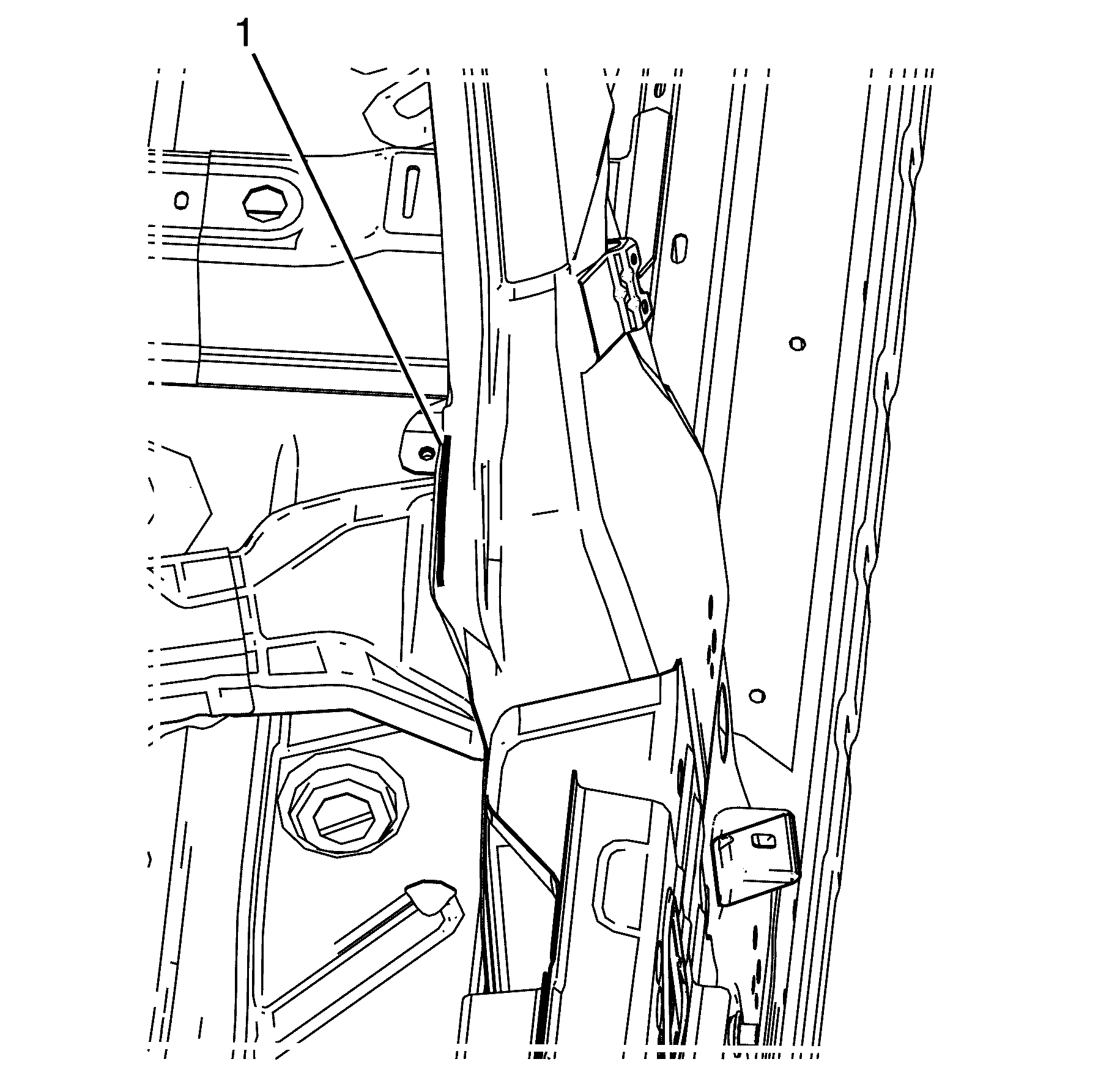
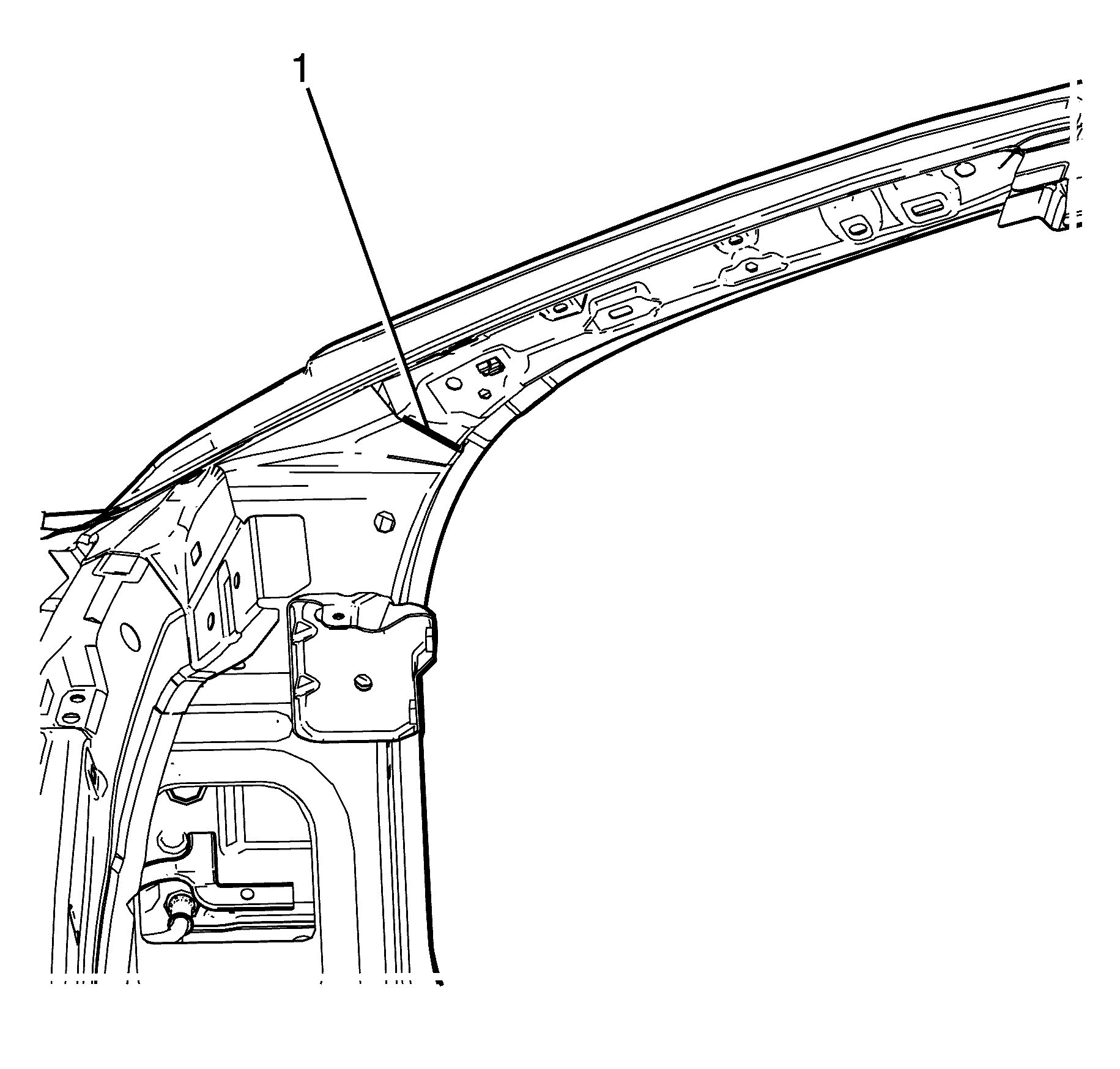
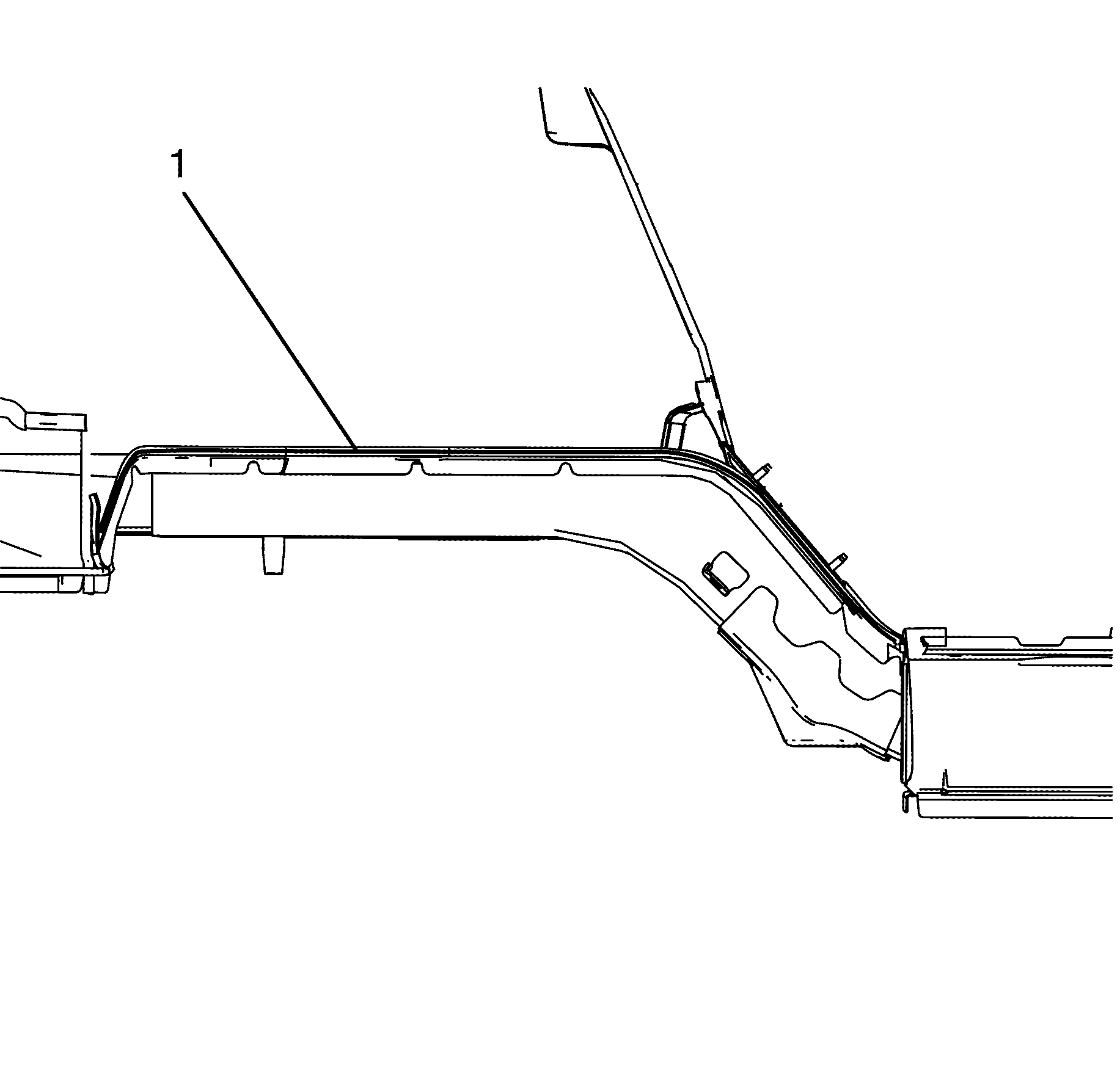
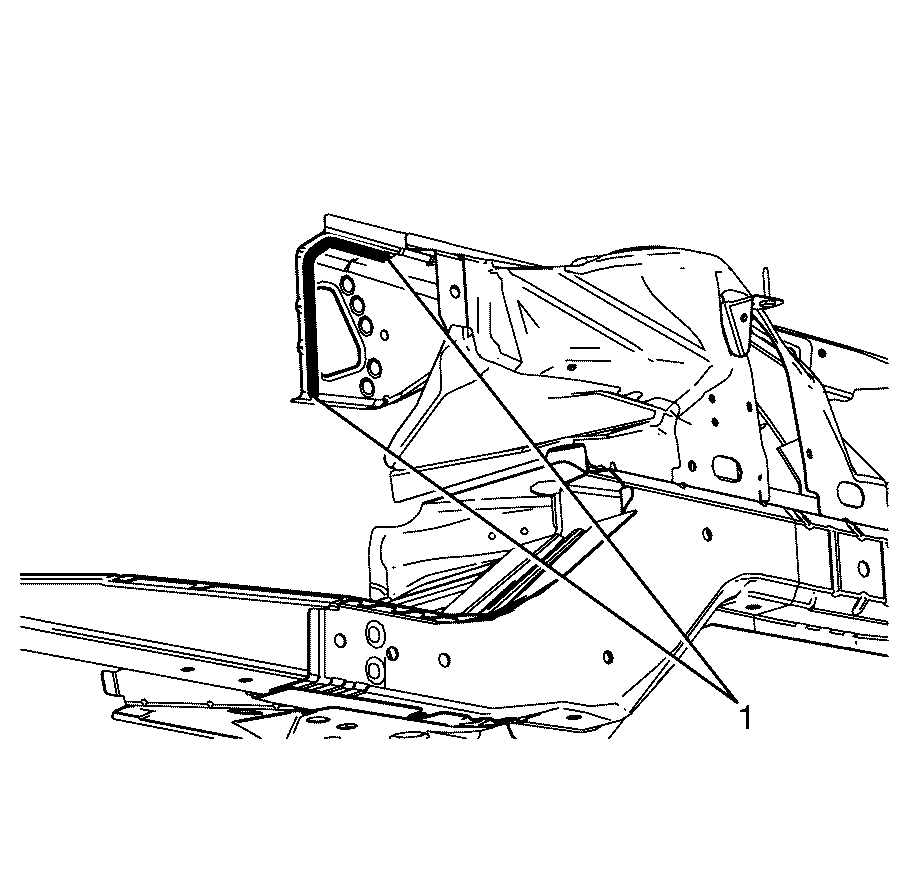
- Remove the body side ring to upper dash panel body sealer (1)
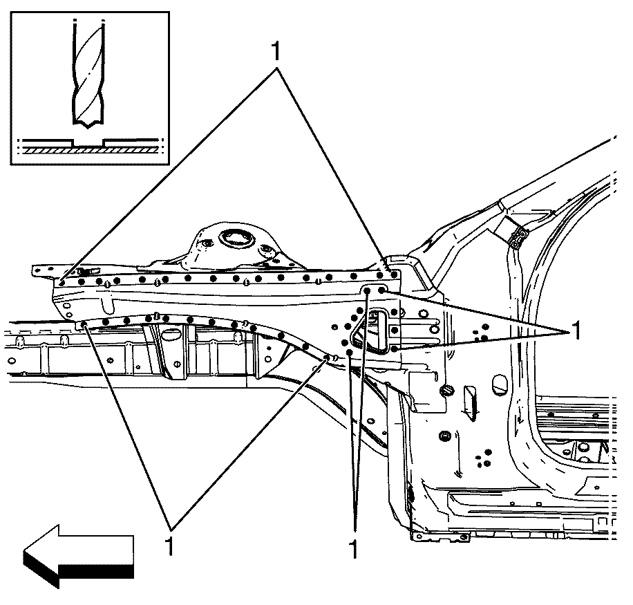
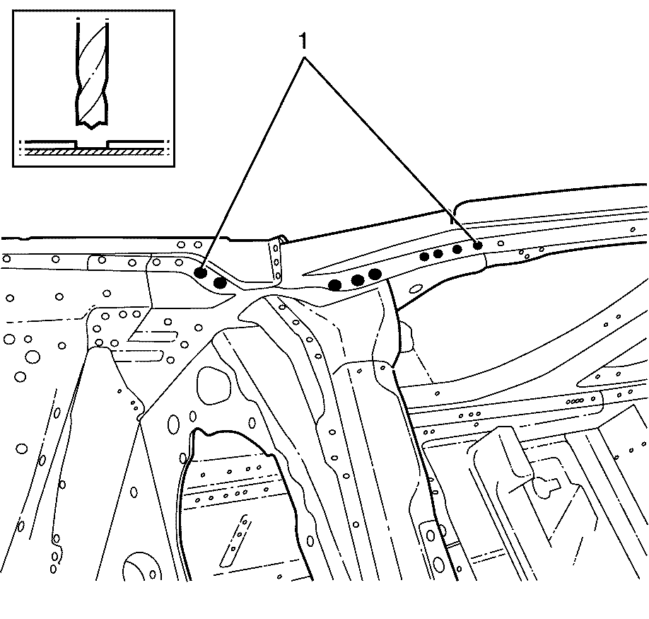
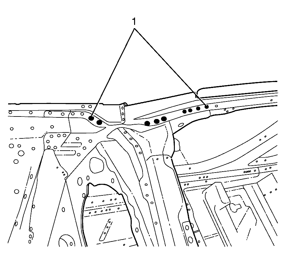
- Locate, mark and drill out the factory welds (1) attaching the upper wheelhouse brace to the front wheelhouse assembly.
- Remove the upper wheelhouse brace from the front wheelhouse assembly.
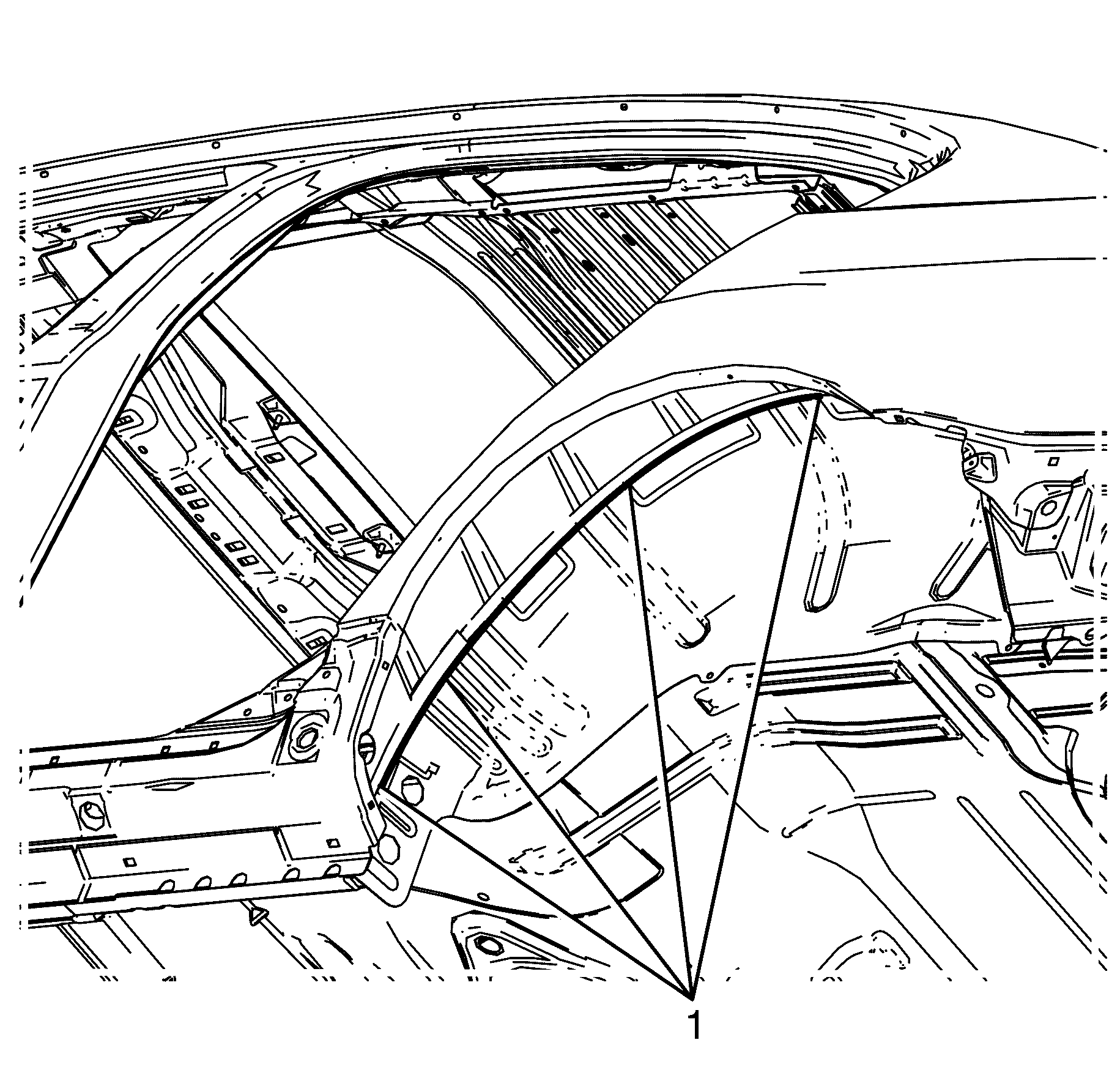
- Locate, mark and drill out the factory welds (1) attaching the upper wheelhouse brace to the front hinge pillar.
- Locate, mark and drill out the factory welds (1) attaching the upper wheelhouse brace to the front hinge pillar.
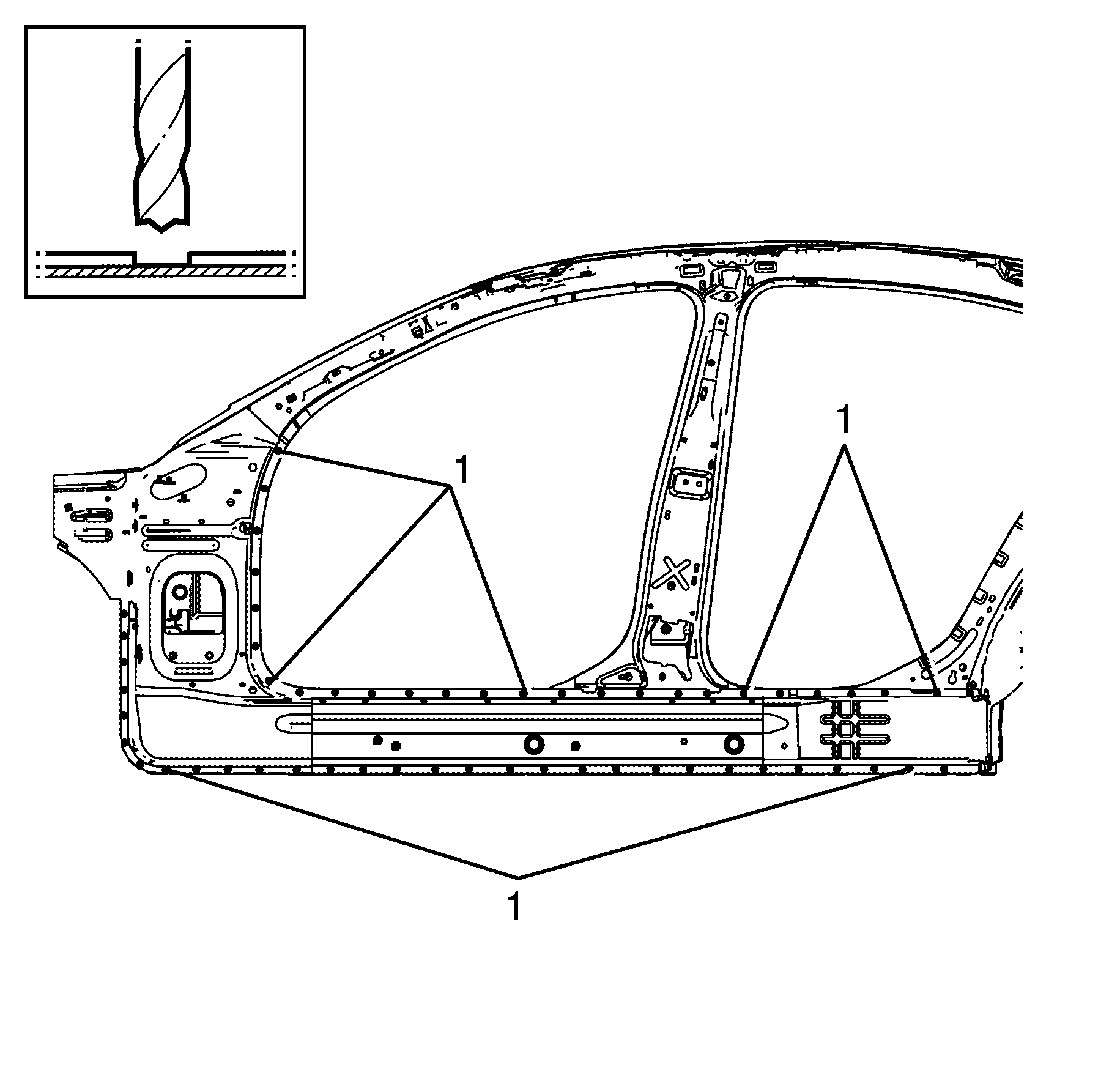
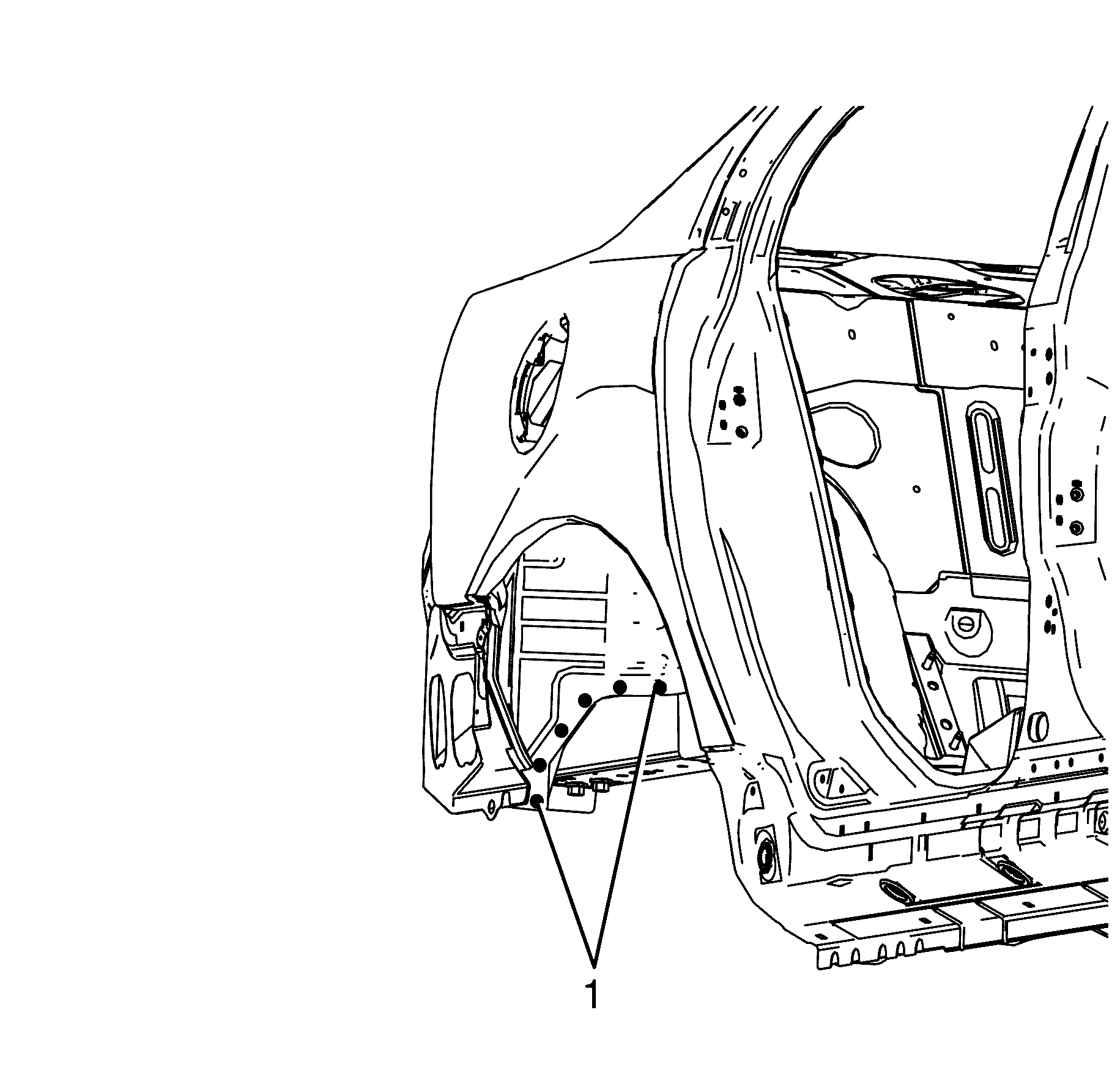
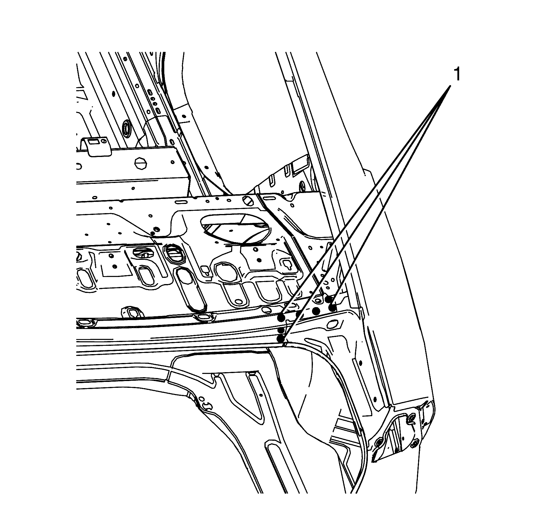
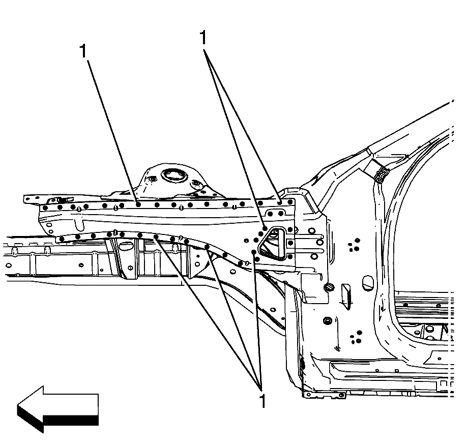
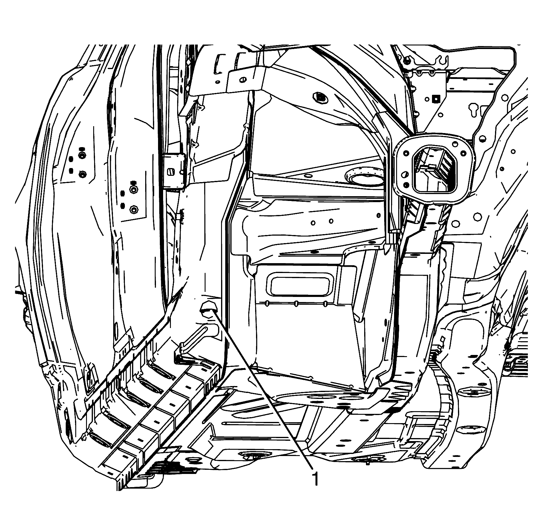
- Locate, mark and drill out the factory welds (1) attaching the body side ring to the front hinge pillar.
- Locate, mark and remove the factory seam welds (1) attaching the body side ring centre pillar to the inner rocker panel.
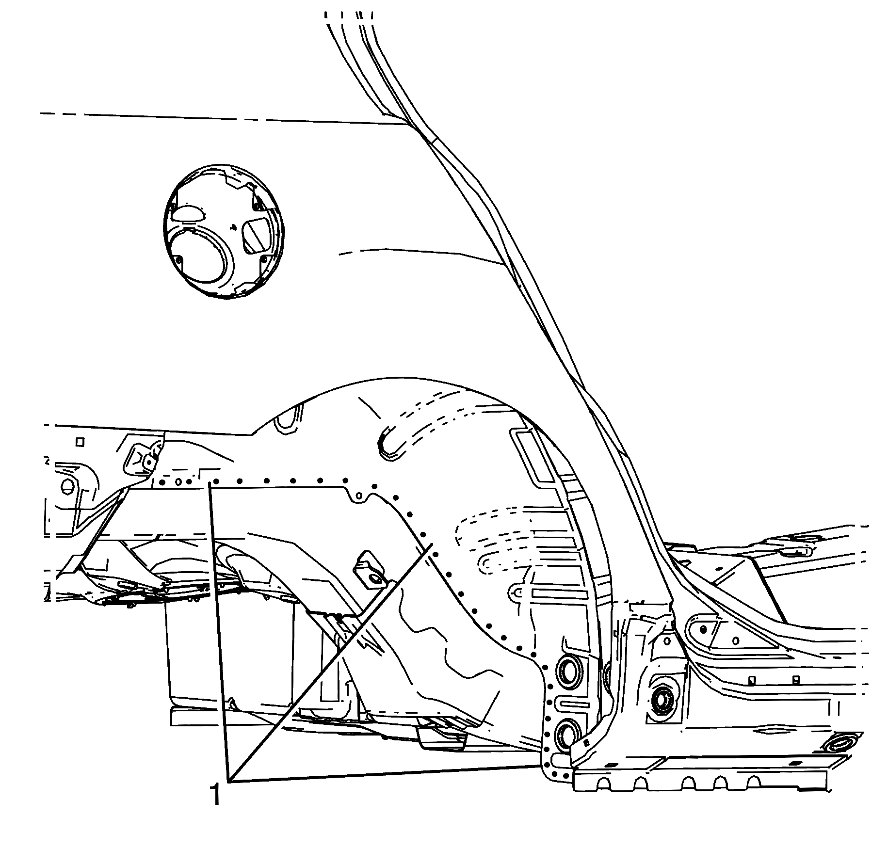
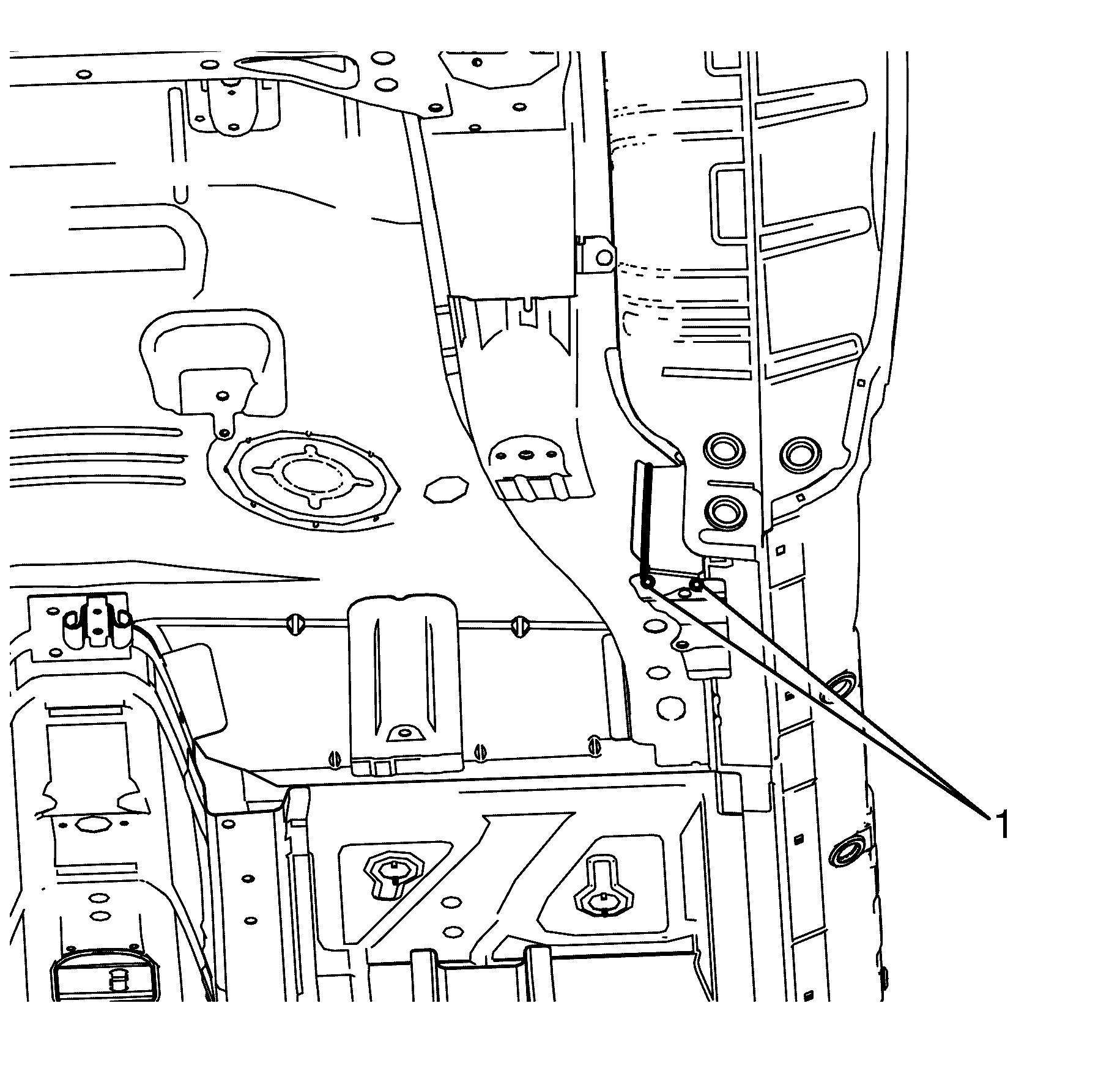
- Locate, mark and remove the factory seam welds (1) attaching the body side ring to the rear inner wheelhouse.
- Locate, mark and remove the factory seam welds (1) attaching the body side ring to the front hinge pillar.
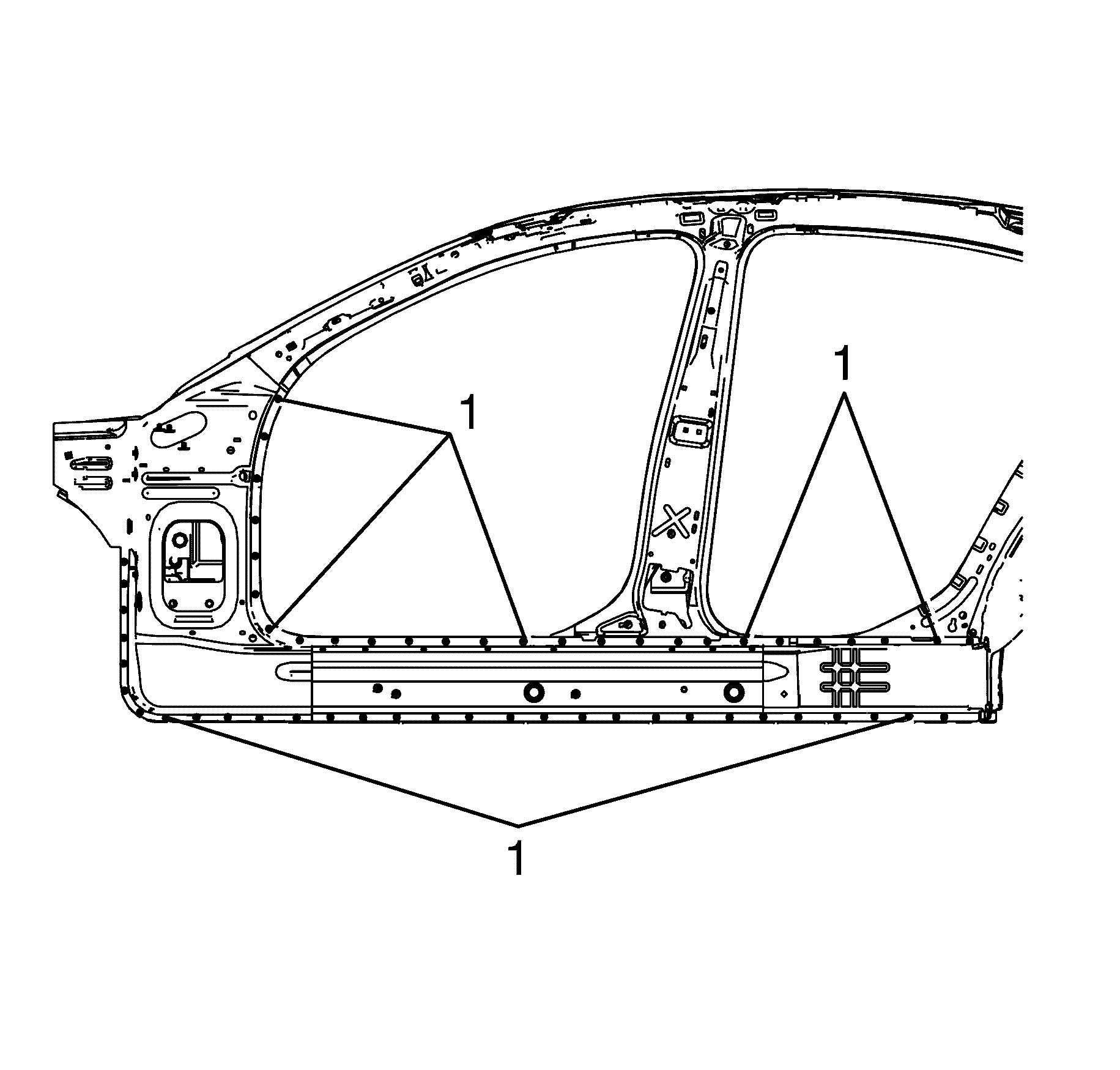
- Locate, mark and drill out the factory welds (1) attaching the body side ring to the vehicle.
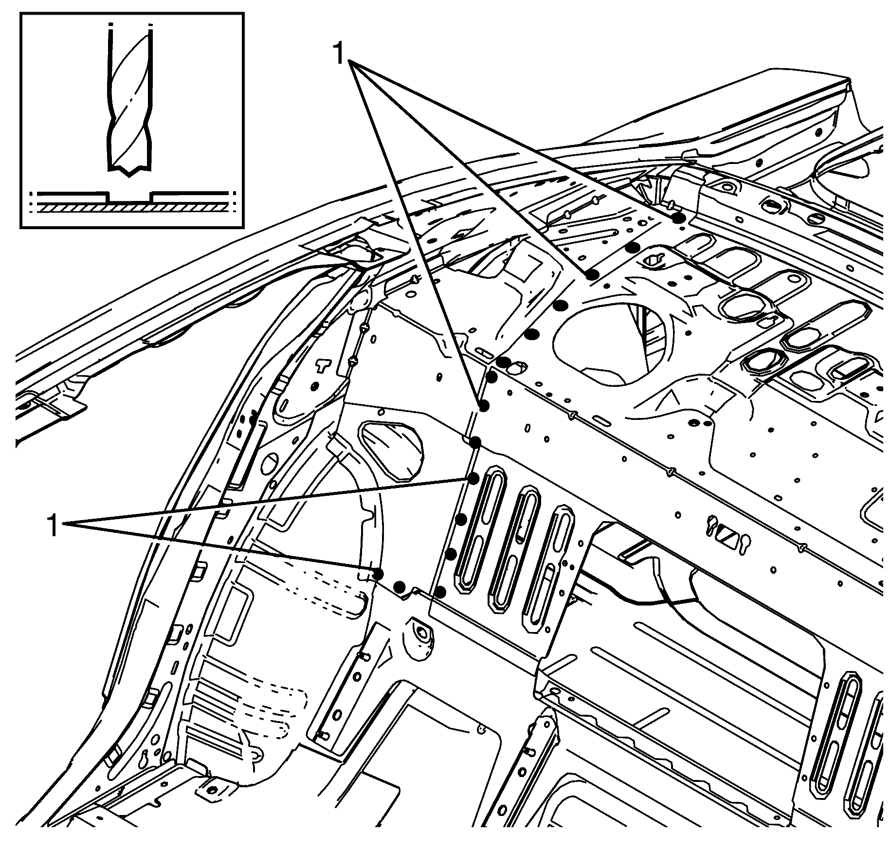
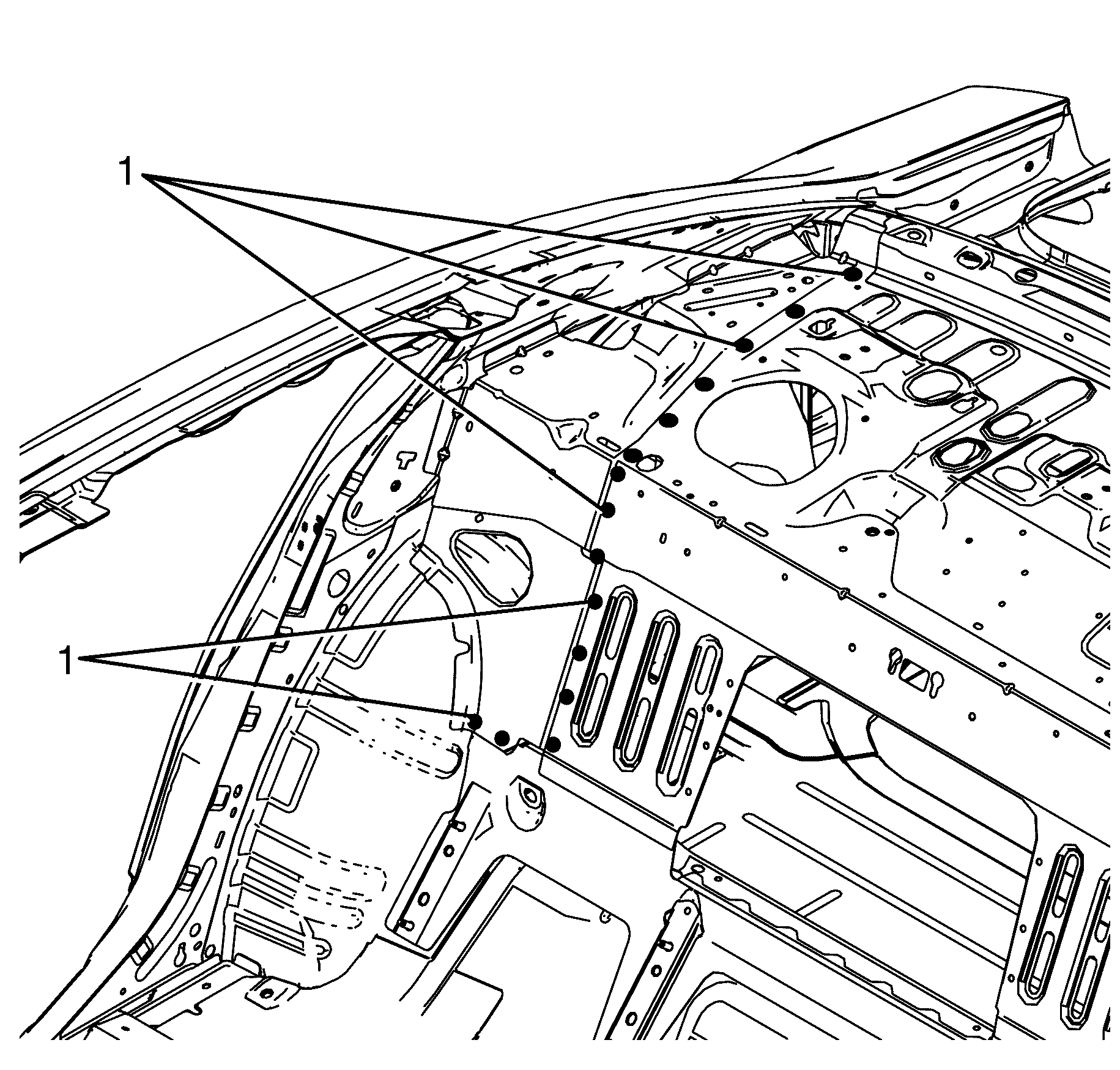
- Locate, mark and drill out the factory welds (1) attaching the body side ring assembly to the parcel shelf assembly.
- Locate, mark and drill out the factory welds (1) attaching the body side ring assembly to the upper parcel shelf assembly.
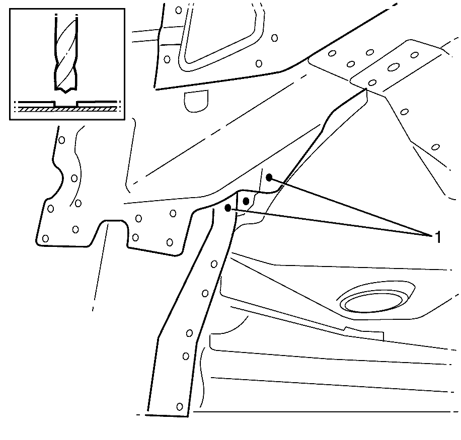
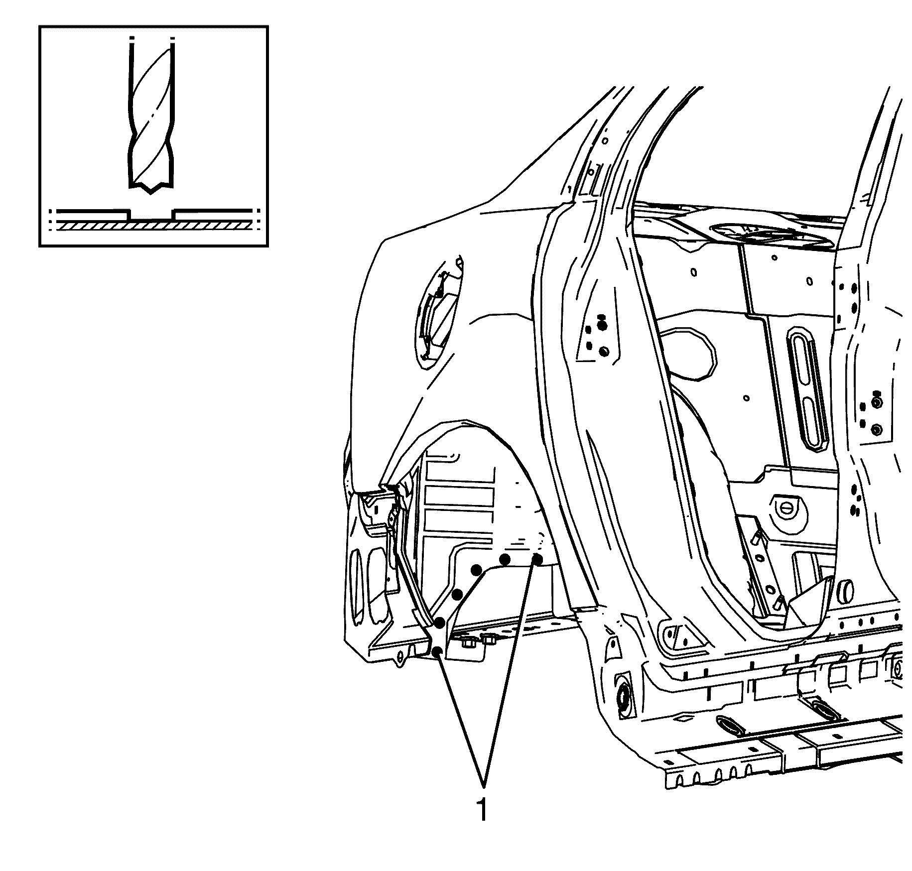
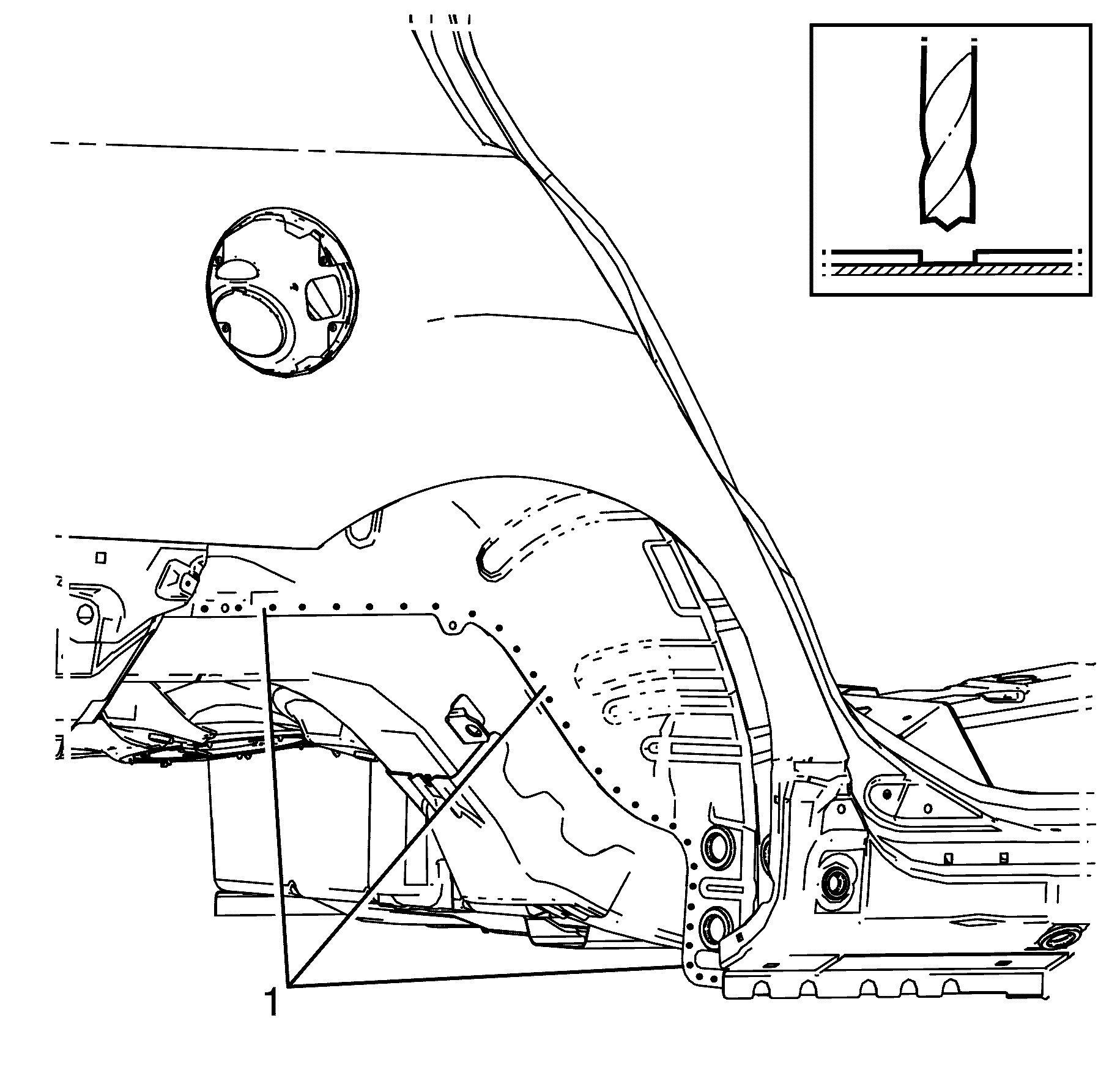
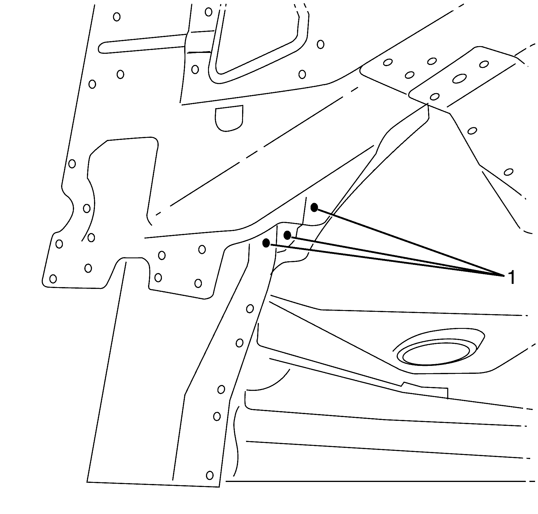
- Locate, mark and drill out the factory welds (1) attaching the body side ring assembly to the inner rear wheelhouse.
- Locate, mark and drill out the factory welds (1) attaching the body side ring assembly to the inner rear wheelhouse.
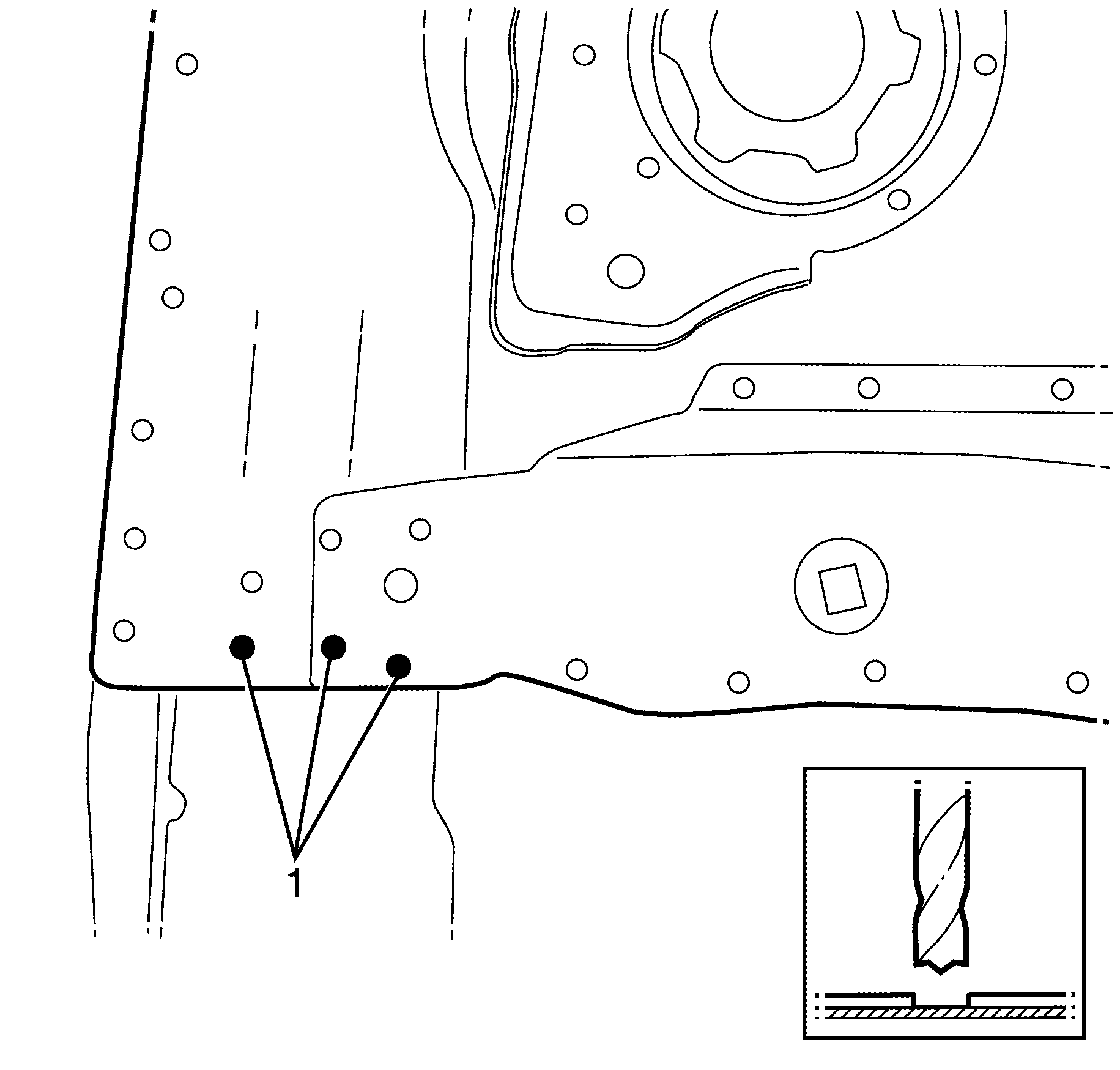
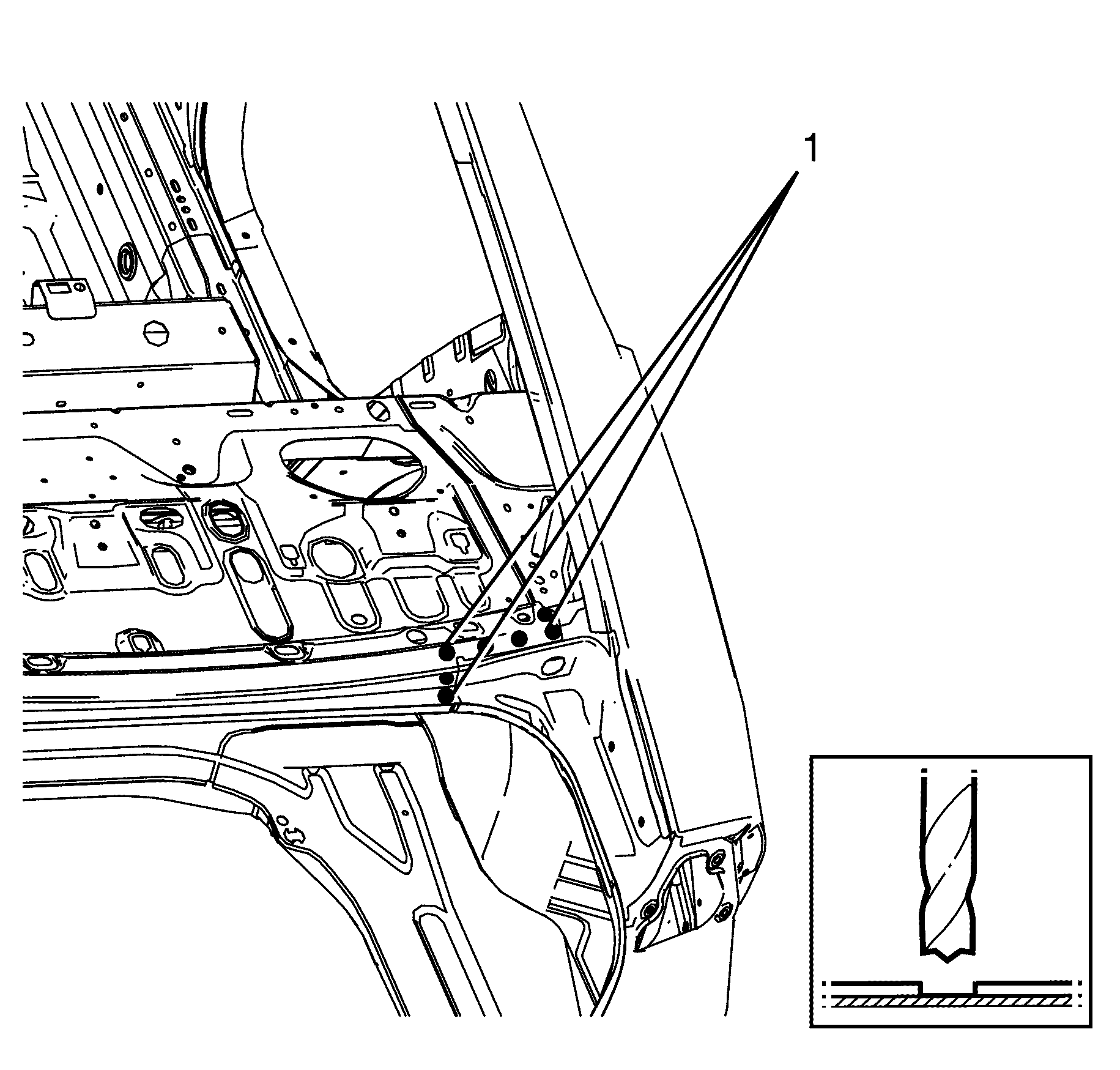
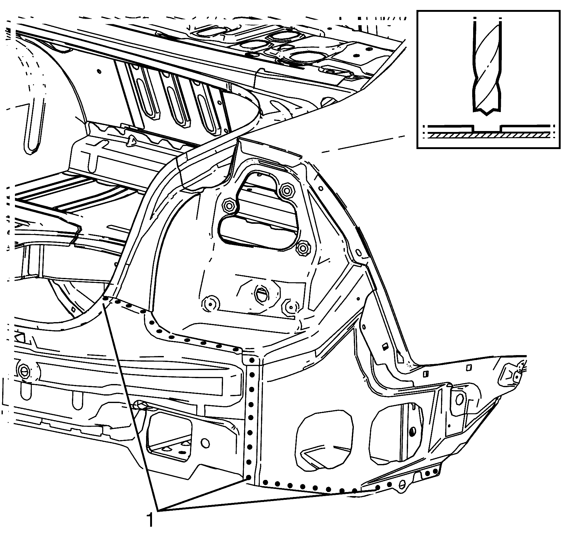
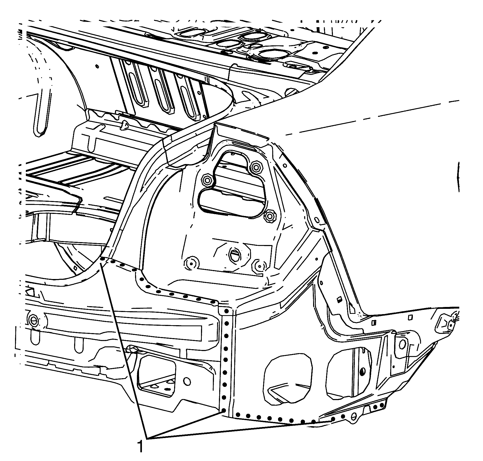
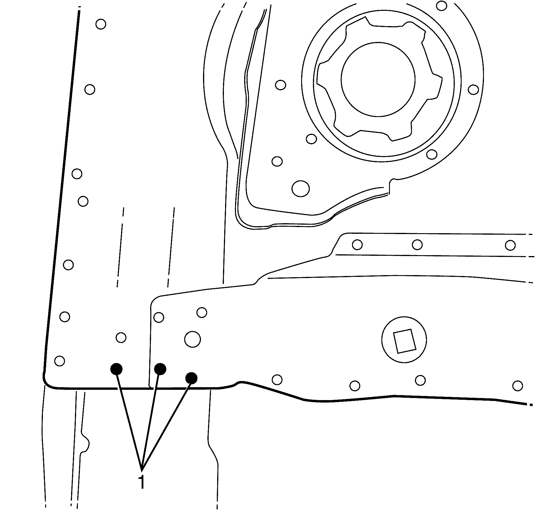
- Locate, mark and drill out the factory welds (1) attaching the body side ring assembly to the rear end panel.
- Remove the body side ring from the vehicle.
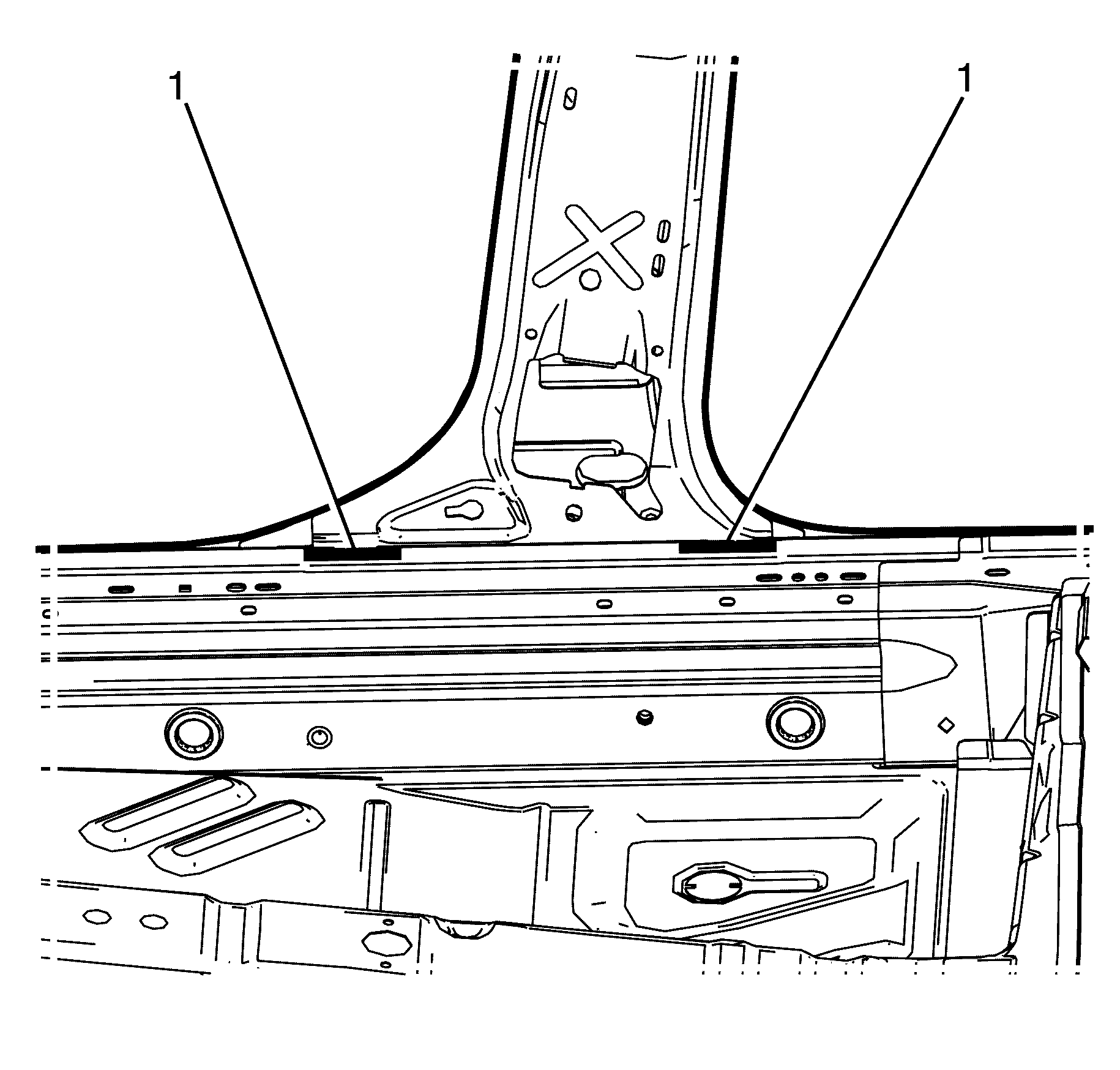
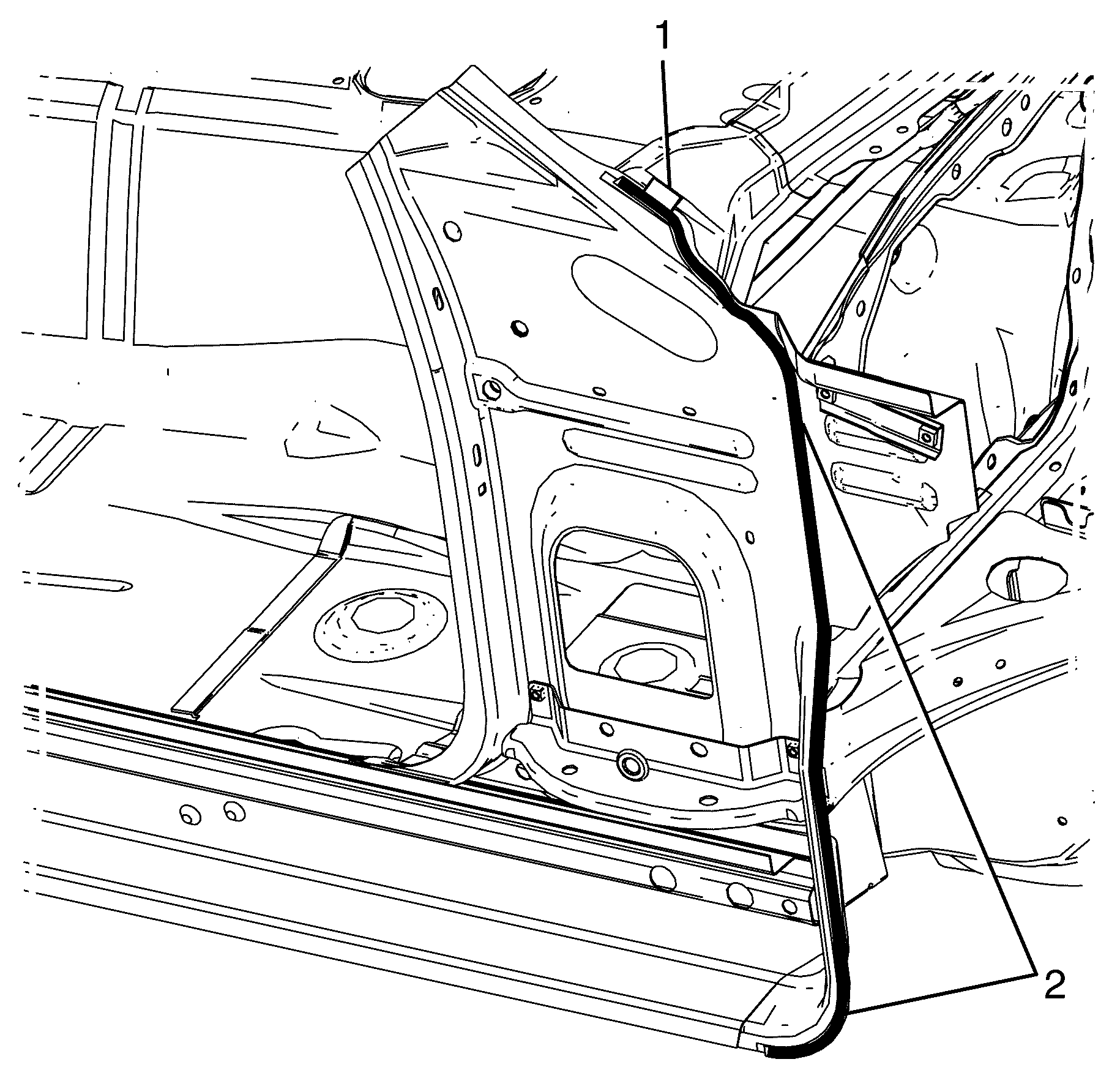
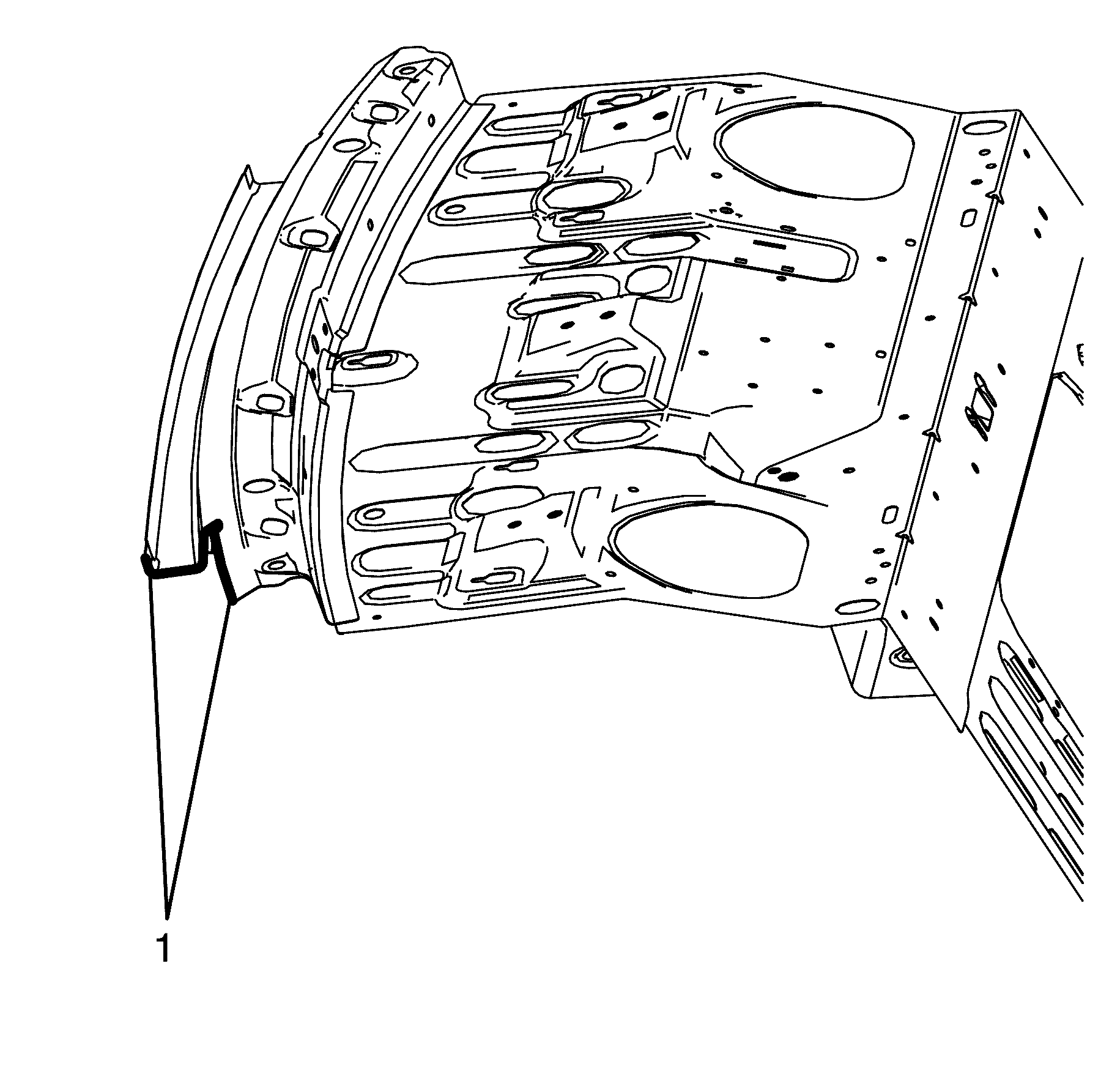
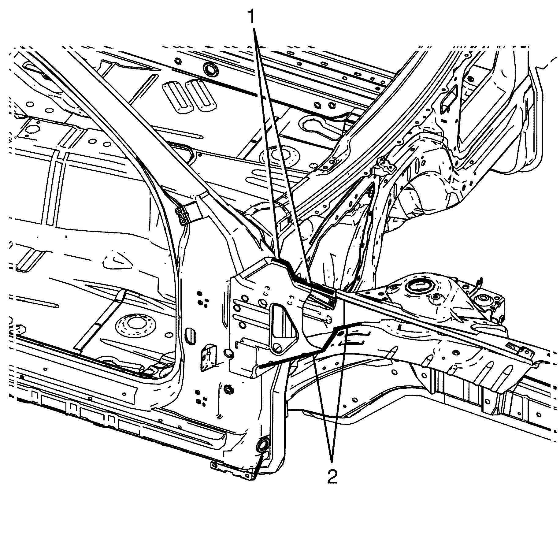
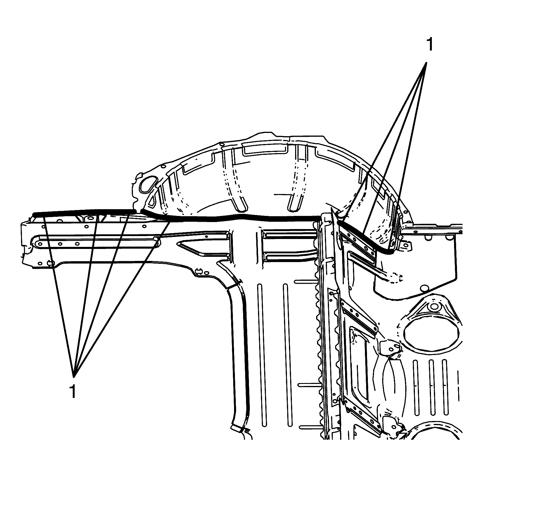
- Remove the sealer (1) from the front plenum panel.
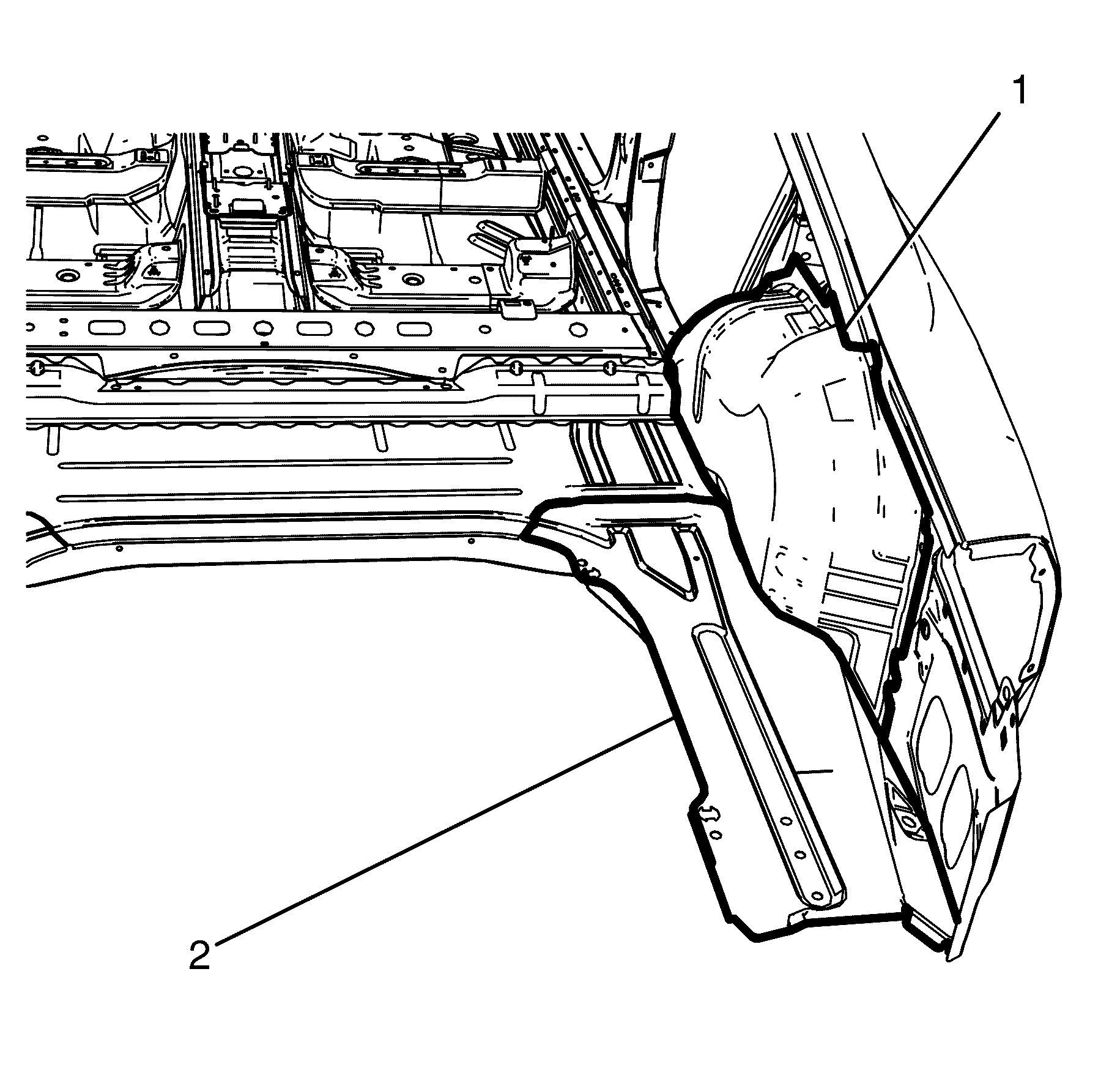
- Remove the seam sealer (2) from the lower hinge pillar.
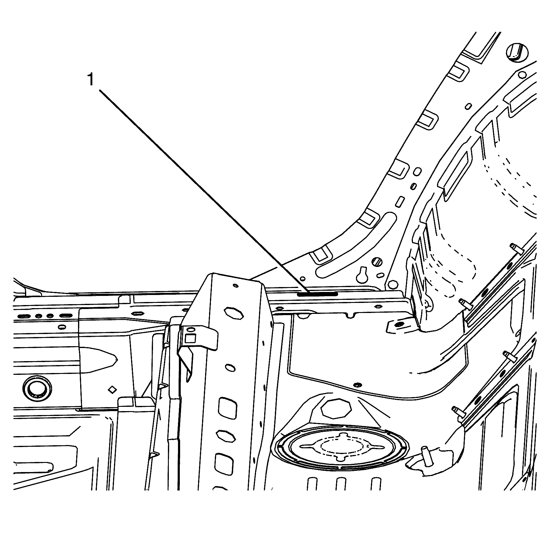
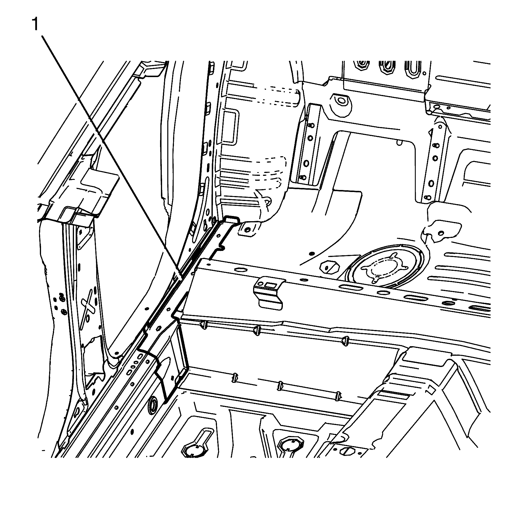
- Remove the seam sealer (1) from the rear floor pan assembly.
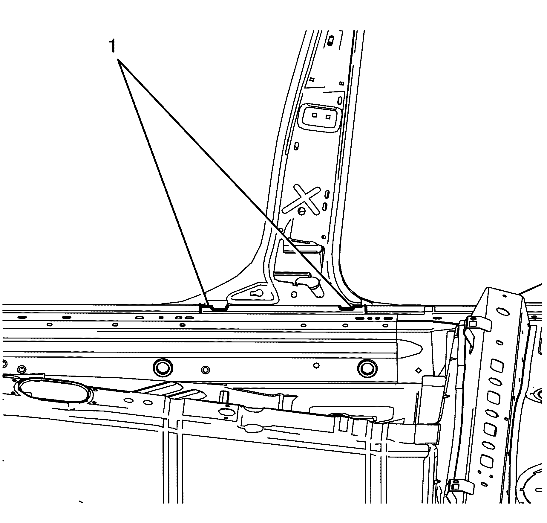
- Remove the seam sealer (1) from the inner side extension panel.
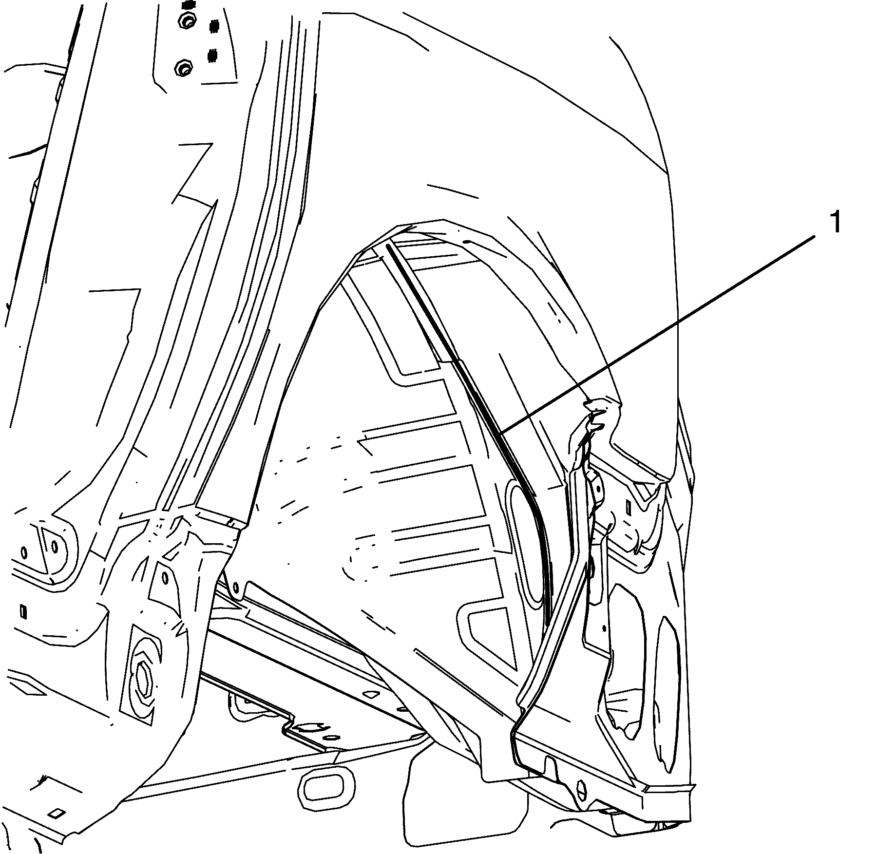
- Remove the seam sealer (1) from the rear end panel.
Caution: Refer to Approved Equipment for Collision Repair Caution in the Preface section.
Caution: Refer to Vehicle Lifting Caution in the Preface section.
Caution: Refer to Safety Glasses Caution in the Preface section.
Caution: Refer to Foam Sound Deadeners Caution in the Preface section.
Caution: Refer to Battery Disconnect Caution in the Preface section.
Important: This step is unique to the right body side ring.
Important: This step is unique to the right body side ring.
Important: This step is unique to the right body side ring.
Important: This step is unique to the sunroof.
Installation Procedure
- Drill 8 mm (5/16 in) plug weld holes as necessary in the locations noted from the original assembly.
- Clean and prepare the mating surfaces of both parts of the body side ring.
- Remove the unexpanded noise baffle (1) from the body side ring.
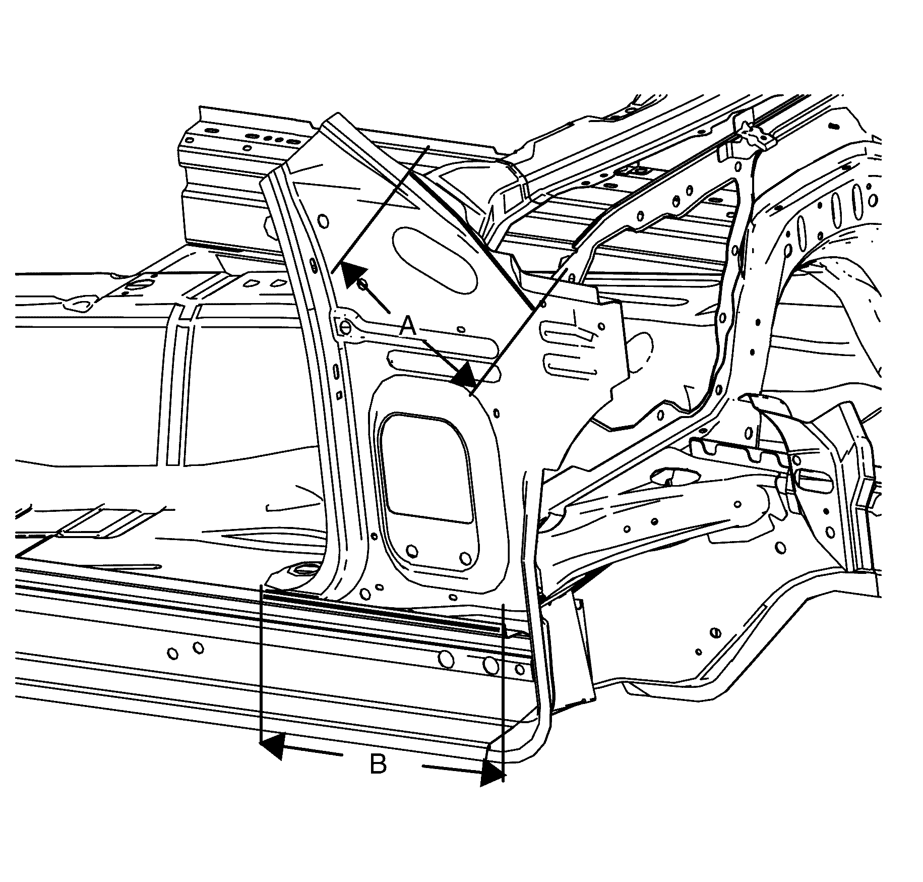
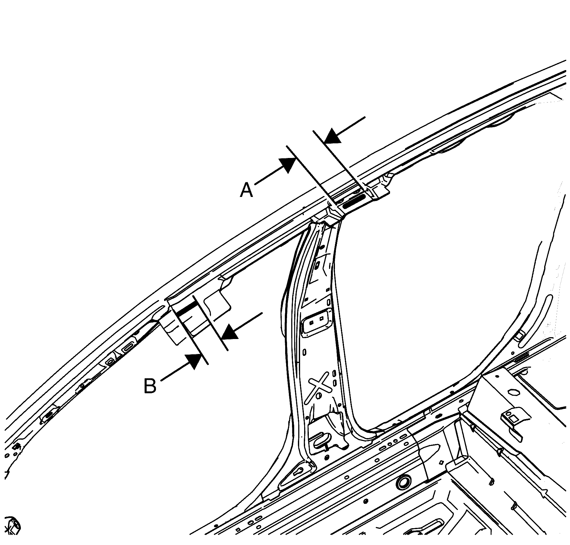
- Apply structural adhesive GM6449G or equivalent 260 mm (10.24 in) (A) to the top edge of the inner hinge pillar.
- Apply structural adhesive GM6449G or equivalent 400 mm (15.75 in) (B) to the inner rocker panel.
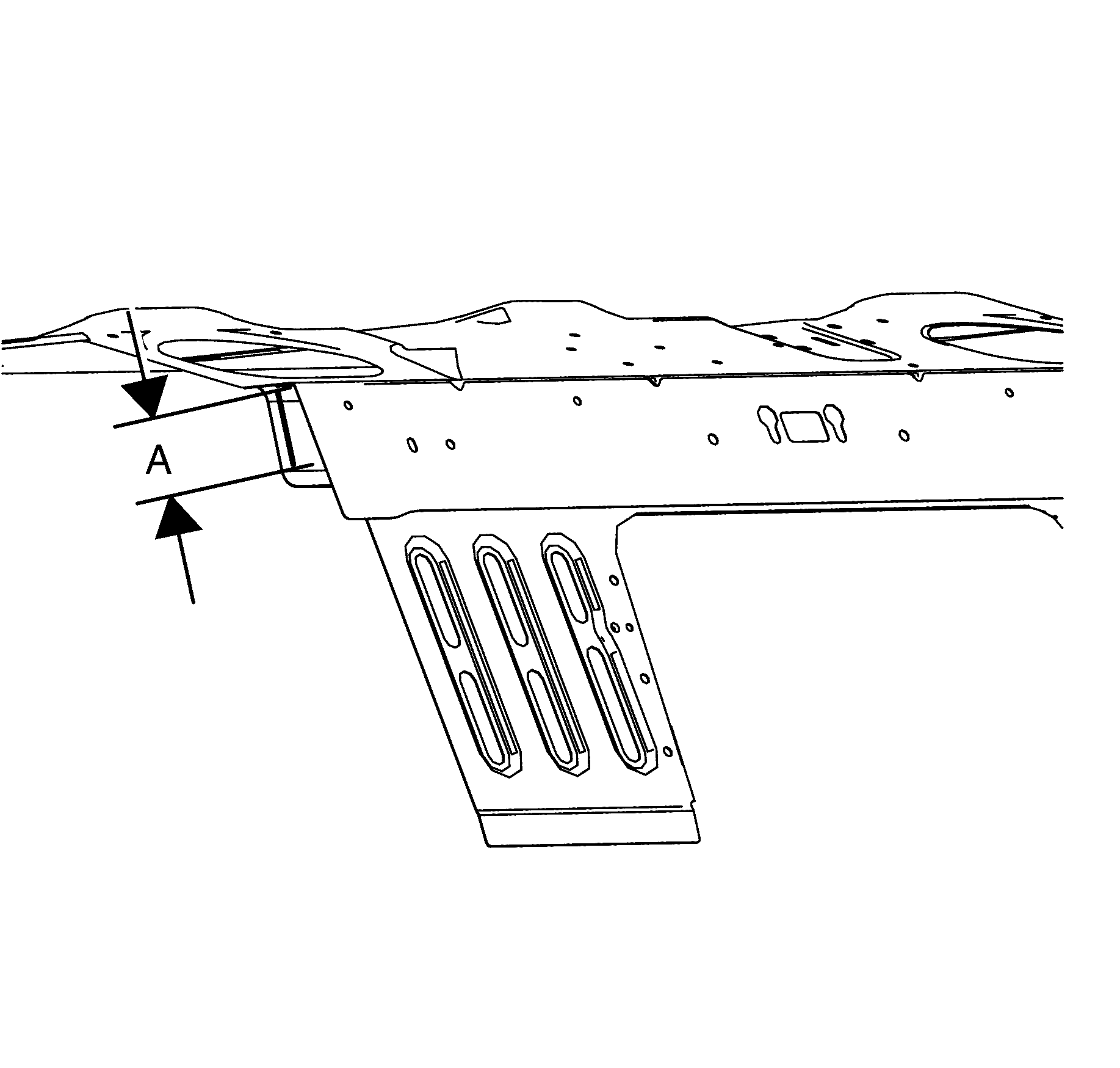
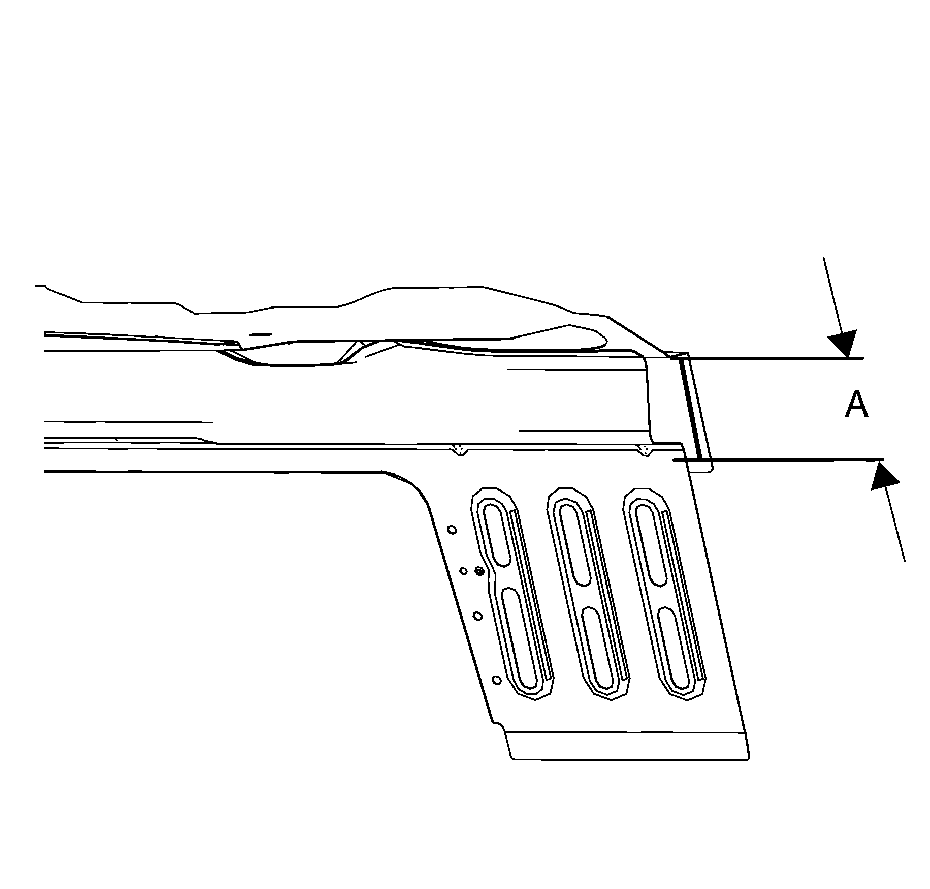
- Apply structural adhesive GM6449G or equivalent 50 mm (1.97 in) (A) to the rear seat back on the forward facing surface.
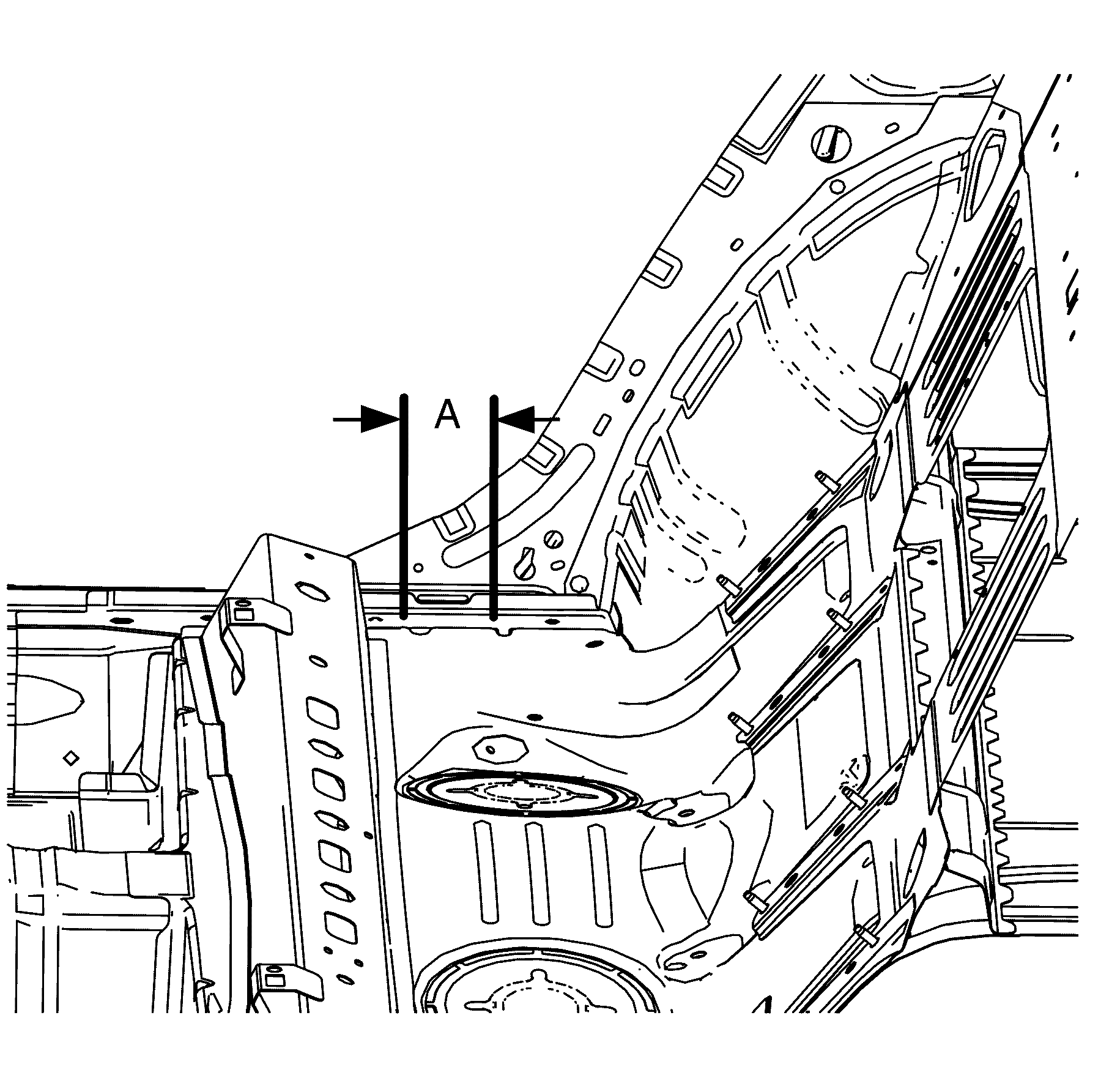
- Apply structural adhesive GM6449G or equivalent 110 mm (4.33 in) (A) to the parcel shelf.
- Apply structural adhesive GM6449G or equivalent 40 mm (1.57 in) (A) to the body side centre roof bow.
- Apply structural adhesive GM6449G or equivalent 60 mm (2.36 (B) to the body side front roof bow.
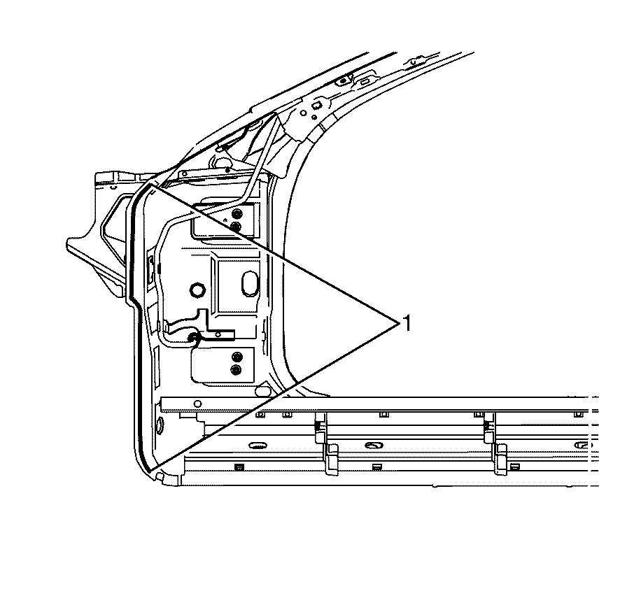
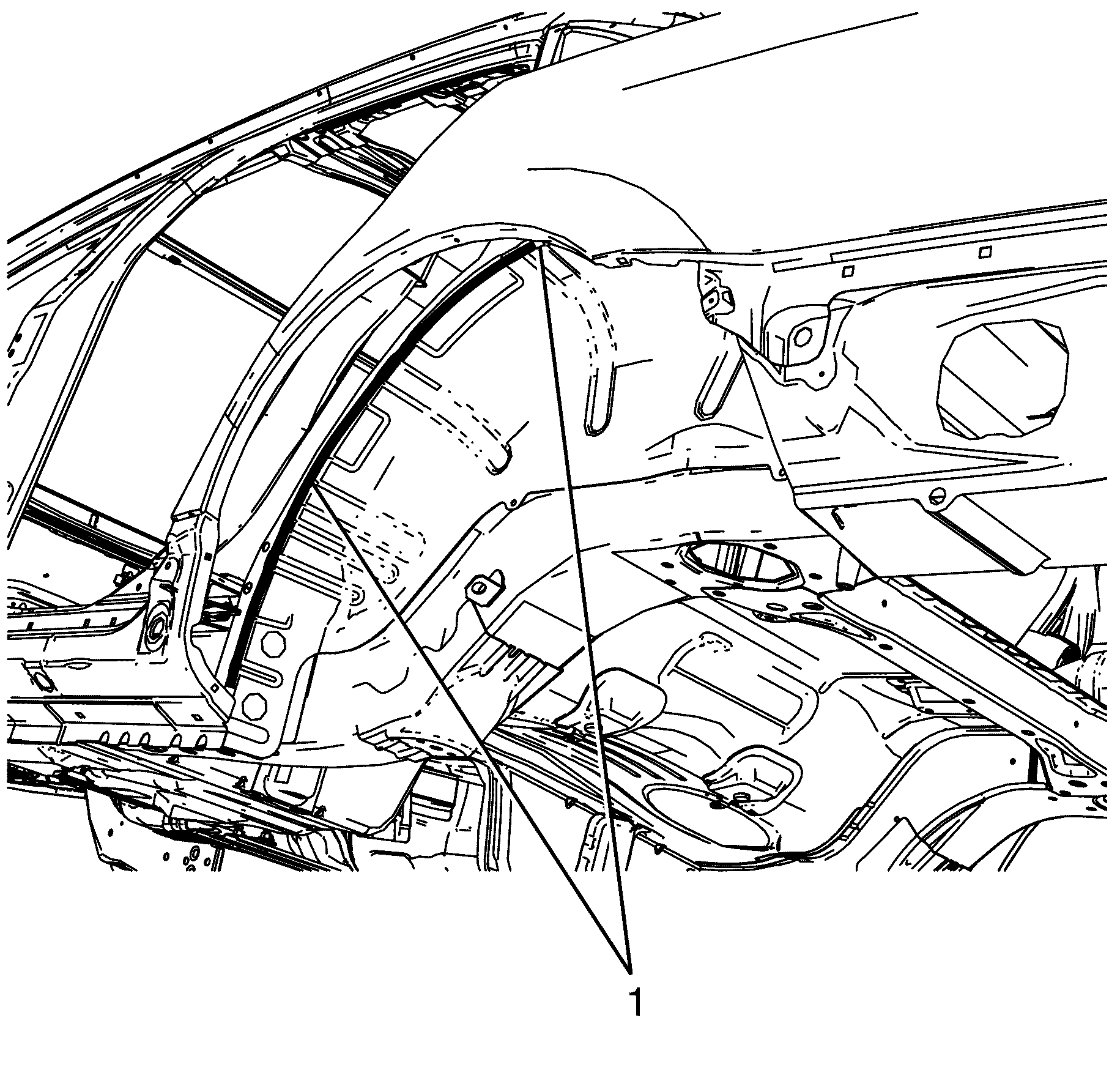
- Apply the primary sealer (1) GM6449G or equivalent along the lower hinge pillar.
- Apply the primary sealer (1) GM6449G or equivalent along the rear edge of the parcel shelf panel.
- Position the body side on the vehicle. Verify correct alignment and position using three-dimensional measuring equipment.
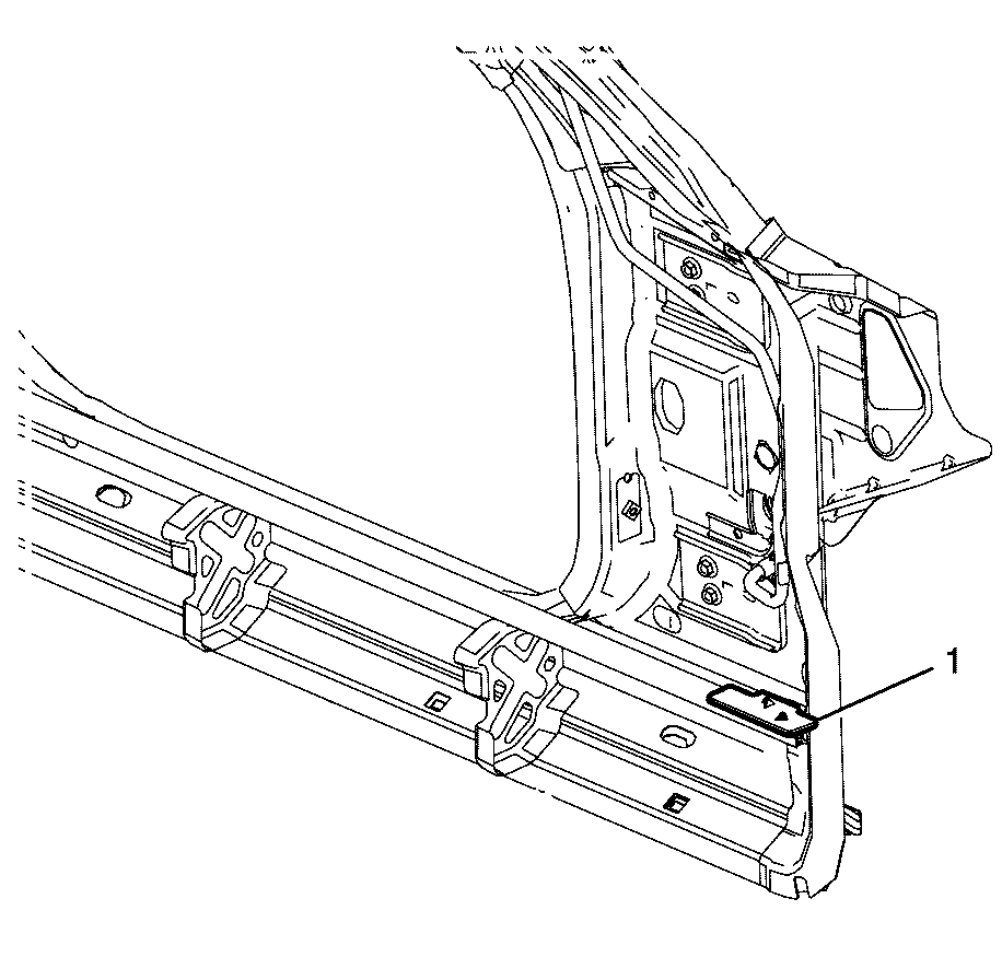
- Align the body side ring to the inner rocker flange tab (1).
- Align the inner rear wheelhouse (1) to side extension panel (2).
- Align the body side ring centre pillar to the indented flange (1) on the inner rocker panel.
- Align the body side ring hinge pillar (2) to the wheelhouse assembly.
- Align the body side ring hinge pillar (1) to the inner lower hinge pillar.
- Seam weld the inner lower hinge pillar to inner upper hinge pillar 60 mm (2.36 in) (A) using a (Metal Inert Gas) MIG welder.
- Seam weld the inner quarter panel to rear floor assembly 60 mm (2.36 in) (A) across the locating tag using a MIG welder.
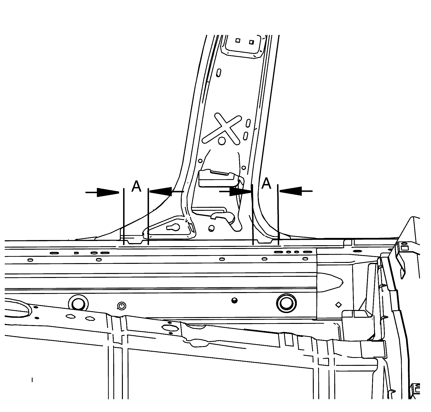
- Seam weld the centre pillar to inner rocker panel in two places 50 mm (1.97 in) (A) across the locating tags using a MIG welder.
- Install the roof. Refer to Roof Outer Replacement .
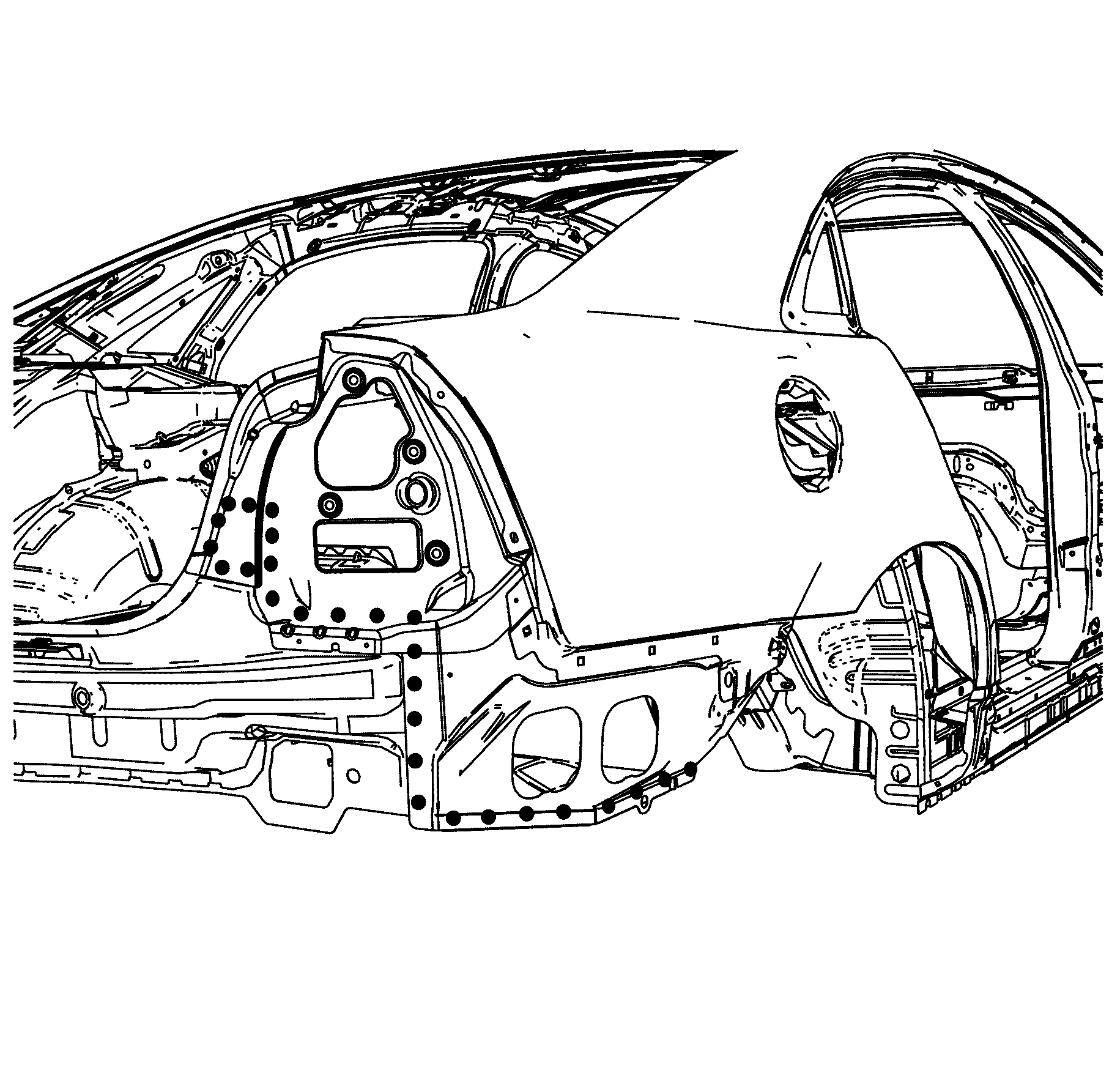
- Weld (1) the body side ring to the vehicle.
- Weld (1) the body side ring to the front hinge pillar.
- Weld (1) the body side ring assembly to the inner rear side extension panel.
- Weld (1) the body side ring assembly to the inner rear wheelhouse.
- Puddle weld (1) the body side ring assembly to the rear end panel.
- Weld (1) the body side ring assembly to the upper parcel shelf assembly.
- Weld (1) the body side ring assembly to the parcel shelf assembly.
- Weld (1) the upper wheelhouse brace to the front hinge pillar.
- Weld (1) the upper wheelhouse brace to the front hinge pillar.
- Apply the primary sealer (1) GM6449G or equivalent along the rear edge of the upper wheelhouse brace.
- Weld (1) the upper wheelhouse brace to the front wheelhouse assembly.
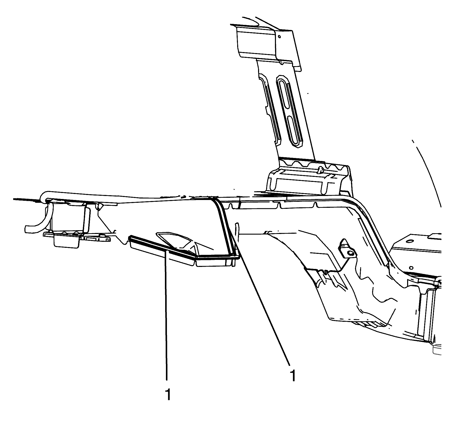
- Apply the secondary sealer (1) GM specification 9984532 or equivalent to the tail lamp and the quarter panel extension.
- Apply the secondary sealer (1) GM specification 9984532 or equivalent along the rear edge of the parcel shelf panel.
- Apply the secondary sealer (1) GM specification 9984532 or equivalent to the quarter panel extension.
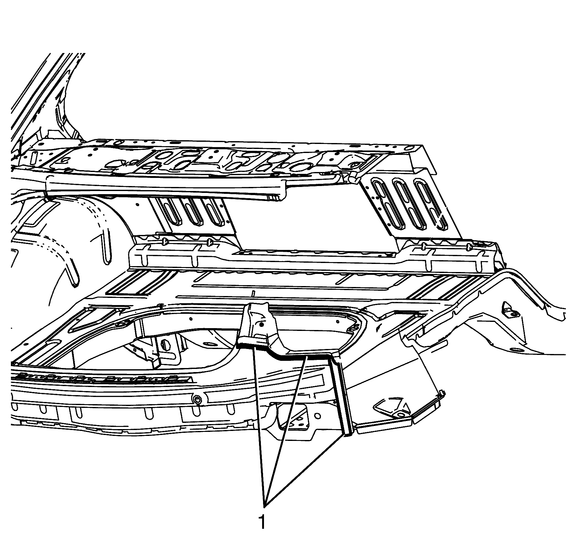
- Apply the secondary sealer (1)GM specification 9984532 or equivalent to the front plenum panel.
- Apply the secondary sealer (2) GM specification 9984532 or equivalent to the lower hinge pillar.
- Apply the secondary sealer (1) GM specification 9984532 or equivalent to the inner rear wheelhouse assembly.
- Apply the secondary sealer (1) GM specification 9984532 or equivalent between the outer rear wheelhouse assembly and the inner rear wheelhouse assembly.
- Apply the secondary sealer (1) GM specification 9984532 or equivalent between the outer rear wheelhouse assembly and the inner rear wheelhouse assembly.
- Apply expanding foam sealer GM9982296 or equivalent to the front lower hinge pillar through the access hole (1).
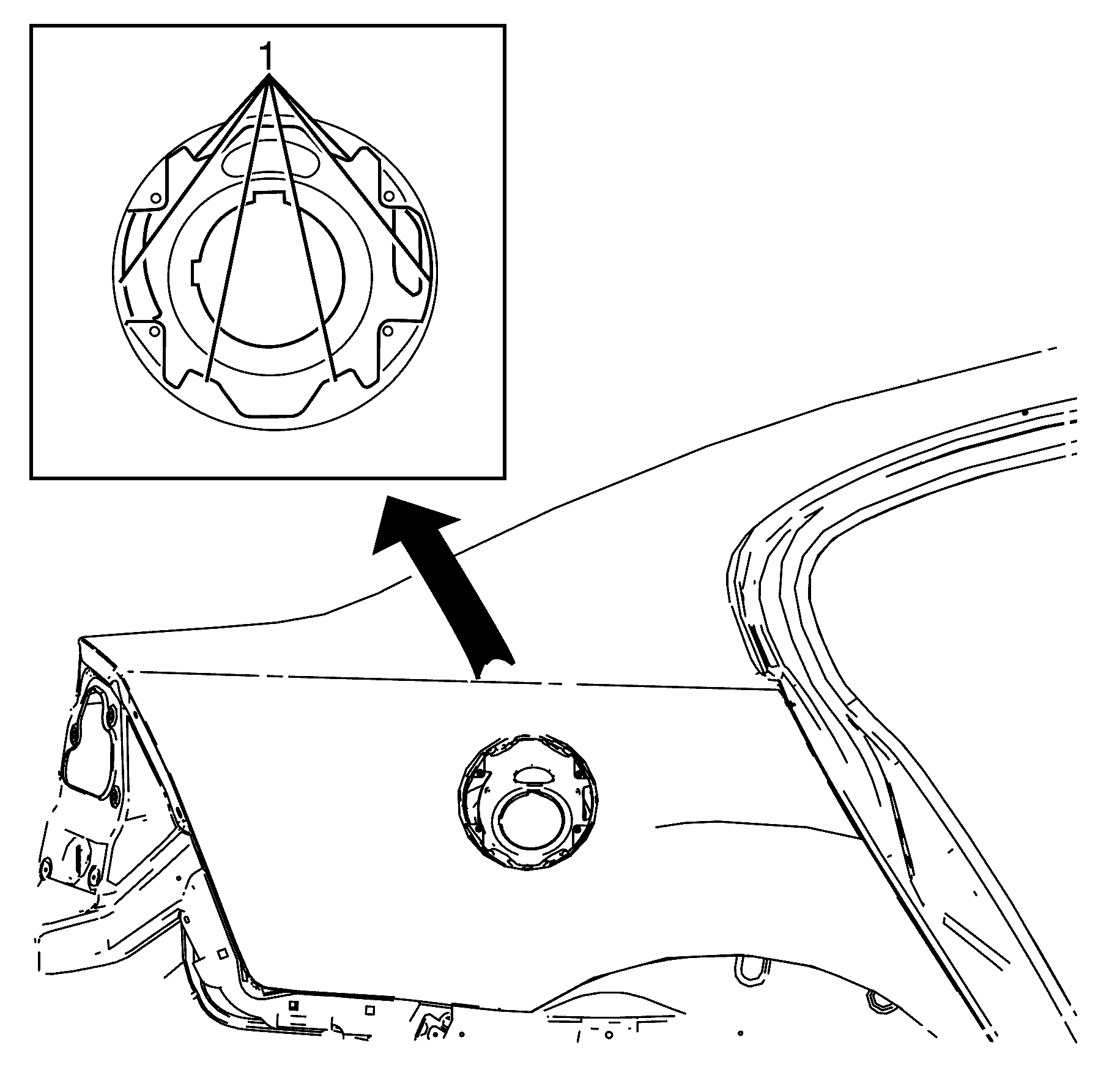
- Apply expanding foam sealer GM9982296 or equivalent through the two access holes (1) in the rear wheelhouse assembly.
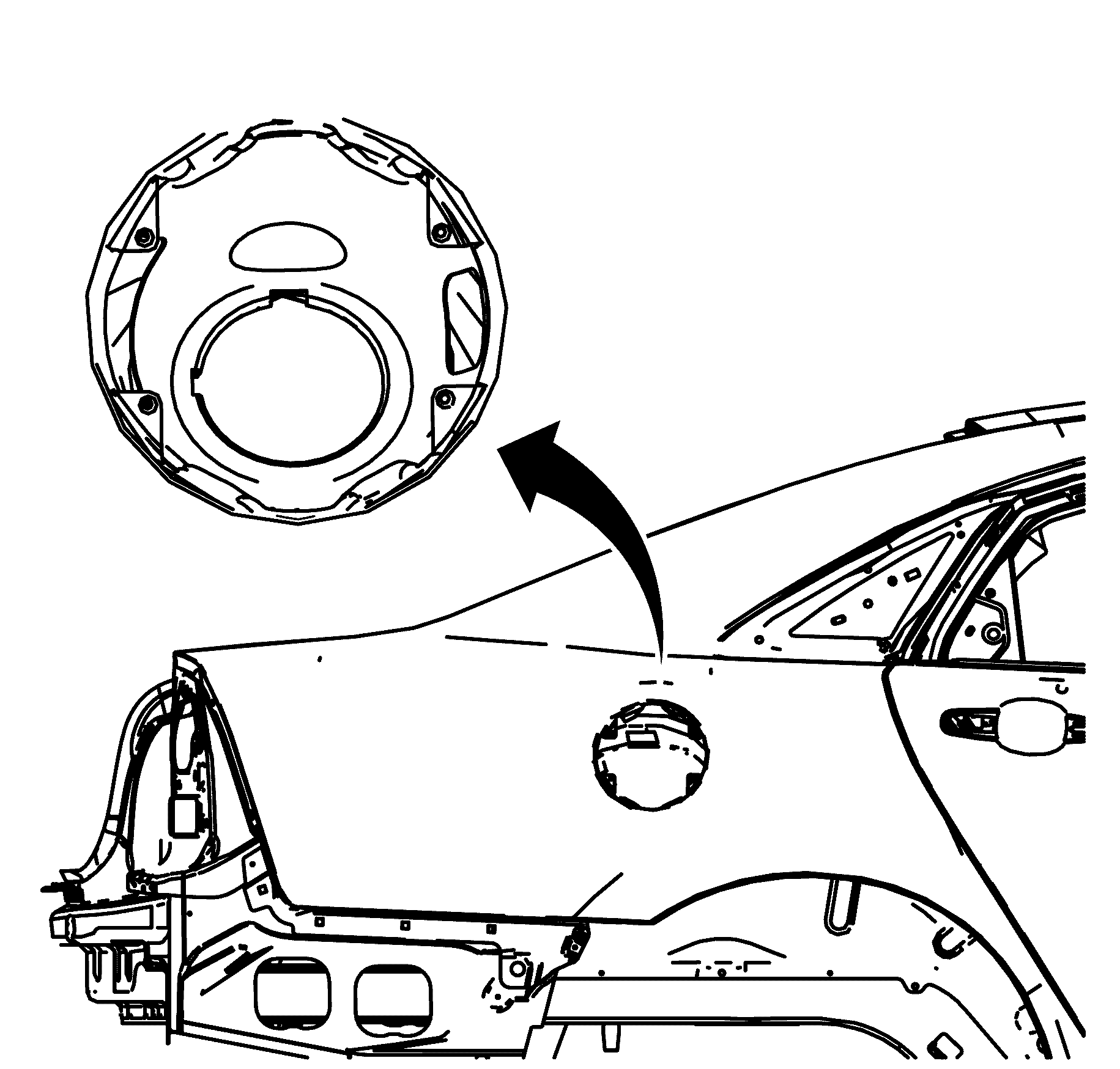
- Apply the secondary sealer (1) GM specification 9984532 or equivalent to the fuel filler pocket.
- Install the positive cable to the vehicle. Refer to Battery Positive Cable Replacement .
- Install the battery tray. Refer to Battery Tray Replacement .
- Install the rear compartment floor carpet. Refer to Rear Compartment Floor Panel Carpet Replacement .
- Install the spare wheel and emergency kit from the rear compartment.
- Install the roof rail module. Refer to Inflatable Restraint Roof Side Rail Module Replacement - Front .
- Install the rear seat belts. Refer to Rear Seat Belt Replacement .
- Install the front seat belts. Refer to Front Seat Belt Replacement .
- Install the rear window shelf trim. Refer to Rear Window Shelf Trim Panel Replacement .
- Install the rear seat back. Refer to Rear Seat Back Replacement .
- Install the rear seat cushion. Refer to Rear Seat Cushion Replacement .
- Install the front seats. Refer to Front Seat Replacement - Bucket .
- Install the HVAC. Refer to HVAC Module Assembly Replacement .
- If re-programming is required. Refer to Control Module References .
- Install the instrument panel. Refer to Instrument Panel Carrier Replacement .
- If re-programming is required. Refer to Control Module References .
- Install the brake master cylinder. Refer to Master Cylinder Replacement .
- Install the ABS unit. Refer to Brake Pressure Modulator Valve Assembly Replacement .
- If re-programming is required. Refer to Control Module References .
- Install the relay box. Refer to Underhood Electrical Center or Junction Block Replacement .
- Install the plenum chamber. Refer to Air Inlet Assembly Replacement .
- Install the air inlet grille. Refer to Air Inlet Grille Panel Replacement .
- Install the front end module. Refer to Front End Panel Module Carrier Assembly Replacement .
- Install the coolant reservoir. Refer to Coolant Recovery Reservoir Replacement .
- Install the fender assembly. Refer to Front Fender Replacement .
- Install the front fascia. Refer to Front Bumper Fascia Replacement .
- Install the rear fascia. Refer to Rear Bumper Fascia Replacement .
- Install the brake lines. Refer to .
- Raise and support the vehicle. Refer to Lifting and Jacking the Vehicle .
- Install the front strut assembly. Refer to Strut Assembly Replacement .
- Install the front wheel hub assembly. Refer to Front Wheel Bearing and Hub Replacement .
- Install the fuel tank. Refer to Fuel Tank Replacement or Fuel Tank Replacement .
- Install the fuel lines. Refer to Fuel Hose/Pipes Replacement - Chassis or Fuel Hose/Pipes Replacement - Engine Compartment .
- Install the fuel filler actuator. Refer to Fuel Tank Filler Door Lock Actuator Replacement .
- Install the fuel filler door. Refer to Fuel Tank Filler Door Lock Actuator Replacement .
- Install the Filler Tube. Refer to Filler Tube Replacement or Filler Tube Replacement .
- Install the rear frame assembly. Refer to Rear Frame Replacement .
- Install the rear wheelhouse liner. Refer to Rear Inner Wheelhouse Replacement .
- Install the front wheelhouse liner. Refer to Front Wheelhouse Liner Replacement .
- Lower the vehicle.
- Install the front doors. Refer to Front Side Door Replacement .
- Install the rear doors. Refer to Rear Door Replacement .
- Install the positive cable to the engine bay. Refer to Battery Positive Cable Replacement .
- Install the negative cable to the engine bay. Refer to Battery Negative Cable Replacement .
- Install the engine assembly. Refer to Engine Replacement or Engine Replacement .
- Connect the negative battery cable. Refer to Battery Negative Cable Disconnection and Connection .
- Enable the SIR system. Refer to SIR Disabling and Enabling .
- If re-programming is required. Refer to Control Module References .
Important: If the location of the original plug weld holes can not be determined, or if structural weld-thru adhesive is present, space the plug weld holes every 32 mm (1¼ in).
Important: Spot welding is the preferred method for attaching panels and should be used wherever possible. A plug weld should be performed where your spot welder is unable reach.



Important: This step is unique to the right body side ring.
Important: This step is unique to the right body side ring.
Important: This step is unique to the right body side ring.
Important: This step is unique to the right body side ring.
Important: This step is unique to the right body side ring.
Side Door Opening Frame Replacement LWB
Removal Procedure
- Disable the SIR system. Refer to SIR Disabling and Enabling .
- Disconnect the negative battery cable. Refer to Battery Negative Cable Disconnection and Connection .
- Remove the front doors. Refer to Front Side Door Replacement .
- Remove the rear doors. Refer to Rear Door Replacement .
- Remove the engine assembly. Refer to Engine Replacement or Engine Replacement .
- Remove the negative cable from the engine bay. Refer to Battery Negative Cable Replacement .
- Remove the positive cable from the engine bay. Refer to Battery Positive Cable Replacement .
- Raise and support the vehicle. Refer to Lifting and Jacking the Vehicle .
- Remove the Filler Tube. Refer to Filler Tube Replacement or Filler Tube Replacement .
- Remove the fuel filler door. Refer to Fuel Tank Filler Door Lock Actuator Replacement .
- Remove the fuel filler actuator. Refer to Fuel Tank Filler Door Lock Actuator Replacement .
- Remove the fuel lines. Refer to Fuel Hose/Pipes Replacement - Chassis or Fuel Hose/Pipes Replacement - Chassis .
- Remove the front wheelhouse liner. Refer to Front Wheelhouse Liner Replacement .
- Remove the rear wheelhouse liner. Refer to Rear Inner Wheelhouse Replacement .
- Remove the rear frame assembly. Refer to Rear Frame Replacement .
- Remove the fuel tank. Refer to Fuel Tank Replacement or Fuel Tank Replacement .
- Remove the front wheel hub assembly. Refer to Front Wheel Bearing and Hub Replacement .
- Remove the front strut assembly. Refer to Strut Assembly Replacement .
- Lower the vehicle.
- Remove the brake lines. Refer to Brake Pipe Replacement .
- Remove the fender assembly. Refer to Front Fender Replacement .
- Remove the front fascia. Refer to Front Bumper Fascia Replacement .
- Remove the rear fascia. Refer to Rear Bumper Fascia Replacement .
- Remove the coolant reservoir. Refer to Coolant Recovery Reservoir Replacement .
- Remove the front end module. Refer to Front End Panel Module Carrier Assembly Replacement .
- Remove the air inlet grille. Refer to Air Inlet Grille Panel Replacement .
- Remove the plenum chamber. Refer to Air Inlet Assembly Replacement .
- Remove the relay box. Refer to Underhood Electrical Center or Junction Block Replacement .
- Remove the ABS unit. Refer to Brake Pressure Modulator Valve Assembly Replacement .
- Remove the brake master cylinder. Refer to Master Cylinder Replacement .
- Remove the instrument panel. Refer to Instrument Panel Carrier Replacement .
- Remove the HVAC. Refer to HVAC Module Assembly Replacement .
- Remove the front seats. Refer to Front Seat Replacement - Bucket .
- Remove the rear seat back. Refer to Rear Seat Back Replacement .
- Remove the rear seat cushion. Refer to Rear Seat Cushion Replacement .
- Remove the rear window shelf trim. Refer to Rear Window Shelf Trim Panel Replacement .
- Remove the front seat belts. Refer to Front Seat Belt Replacement .
- Remove the rear seat belts. Refer to Rear Seat Belt Replacement .
- Remove the roof rail module. Refer to Inflatable Restraint Roof Side Rail Module Replacement - Front .
- Remove the spare wheel and emergency kit from the rear compartment.
- Remove the rear compartment floor carpet. Refer to Rear Compartment Floor Panel Carpet Replacement .
- Remove the battery tray. Refer to Battery Tray Replacement .
- Remove the positive cable from the vehicle. Refer to Battery Positive Cable Replacement .
- Remove the sunroof module. Refer to Sunroof Module Assembly Replacement .
- Remove the roof. Refer to Roof Outer Replacement .
- Note the location and remove the sealers and anti-corrosion materials from the repair area, as necessary. Refer to Anti-Corrosion Treatment and Repair .
- Remove the body side ring to upper dash panel body sealer (1)
- Locate, mark and drill out the factory welds (1) attaching the upper wheelhouse brace to the front wheelhouse assembly.
- Remove the upper wheelhouse brace from the front wheelhouse assembly.
- Locate, mark and drill out the factory welds (1) attaching the upper wheelhouse brace to the front hinge pillar.
- Locate, mark and drill out the factory welds (1) attaching the upper wheelhouse brace to the front hinge pillar.
- Locate, mark and drill out the factory welds (1) attaching the body side ring to the front hinge pillar.
- Locate, mark and remove the factory seam welds (1) attaching the body side ring centre pillar to the inner rocker panel.
- Locate, mark and remove the factory seam welds (1) attaching the body side ring to the rear inner wheelhouse.
- Locate, mark and remove the factory seam welds (1) attaching the body side ring to the front hinge pillar.
- Locate, mark and drill out the factory welds (1) attaching the body side ring to the vehicle.
- Locate, mark and drill out the factory welds (1) attaching the body side ring assembly to the parcel shelf assembly.
- Locate, mark and drill out the factory welds (1) attaching the body side ring assembly to the upper parcel shelf assembly.
- Locate, mark and drill out the factory welds (1) attaching the body side ring assembly to the inner rear wheelhouse.
- Locate, mark and drill out the factory welds (1) attaching the body side ring assembly to the inner rear wheelhouse.
- Locate, mark and drill out the factory welds (1) attaching the body side ring assembly to the rear end panel.
- Remove the body side ring from the vehicle.
- Remove the sealer (1) from the front plenum panel.
- Remove the seam sealer (2) from the lower hinge pillar.
- Remove the seam sealer (1) from the rear floor pan assembly.
- Remove the seam sealer (1) from the inner side extension panel.
- Remove the seam sealer (1) from the rear end panel.
Caution: Refer to Approved Equipment for Collision Repair Caution in the Preface section.
Caution: Refer to Vehicle Lifting Caution in the Preface section.
Caution: Refer to Safety Glasses Caution in the Preface section.
Caution: Refer to Foam Sound Deadeners Caution in the Preface section.
Caution: Refer to Battery Disconnect Caution in the Preface section.
Important: This step is unique to the right body side ring.
Important: This step is unique to the right body side ring.
Important: This step is unique to the right body side ring.
Important: This step is unique to the sunroof.


Installation Procedure
- Drill 8 mm (5/16 in) plug weld holes as necessary in the locations noted from the original assembly.
- Clean and prepare the mating surfaces of both parts of the body side ring.
- Remove the unexpanded noise baffle (1) from the body side ring.
- Apply structural adhesive (1) GM6449G or equivalent 260 mm (10.24 in) (A) to the top edge of the inner hinge pillar.
- Apply structural adhesive (1) GM6449G or equivalent 400 mm (15.75 in) (B) to the inner rocker panel.
- Apply structural adhesive (1) GM6449G or equivalent 50 mm (1.97 in) (A) to the rear seat back on the forward facing surface.
- Apply structural adhesive (1) GM6449G or equivalent 110 mm (4.33 in) (A) to the parcel shelf.
- Apply structural adhesive (1) GM6449G or equivalent 40 mm (1.57 in) (A) to the body side centre roof bow.
- Apply structural adhesive (1) GM6449G or equivalent 60 mm (2.36 (B) to the body side front roof bow.
- Apply the primary sealer (1) GM6449G or equivalent along the lower hinge pillar.
- Apply the primary sealer (1) GM6449G or equivalent along the rear edge of the parcel shelf panel.
- Position the body side on the vehicle. Verify correct alignment and position using three-dimensional measuring equipment.
- Align the body side ring to the inner rocker flange tab (1).
- Align the inner rear wheelhouse (1) to side extension panel (2).
- Align the body side ring centre pillar to the indented flange (1) on the inner rocker panel.
- Align the body side ring hinge pillar (2) to the wheelhouse assembly.
- Align the body side ring hinge pillar (1) to the inner lower hinge pillar.
- Seam weld the inner lower hinge pillar to inner upper hinge pillar 60 mm (2.36 in) (A) using a (Metal Inert Gas) MIG welder.
- Seam weld the inner quarter panel to rear floor assembly 60 mm (2.36 in) (A) across the locating tag using a MIG welder.
- Seam weld the centre pillar to inner rocker panel in two places 50 mm (1.97 in) (A) across the locating tags using a MIG welder.
- Install the roof. Refer to Roof Outer Replacement .
- Weld (1) the body side ring to the vehicle.
- Weld (1) the body side ring to the front hinge pillar.
- Weld (1) the body side ring assembly to the inner rear side extension panel.
- Weld (1) the body side ring assembly to the inner rear wheelhouse.
- Weld (1) the body side ring assembly to the rear end panel.
- Weld (1) the body side ring assembly to the upper parcel shelf assembly.
- Weld (1) the body side ring assembly to the parcel shelf assembly.
- Weld (1) the upper wheelhouse brace to the front hinge pillar.
- Weld (1) the upper wheelhouse brace to the front hinge pillar.
- Apply the primary sealer (1) GM6449G or equivalent along the rear edge of the upper wheelhouse brace.
- Weld (1) the upper wheelhouse brace to the front wheelhouse assembly.
- Apply the secondary sealer (1) GM specification 9984532 or equivalent to the tail lamp and the quarter panel extension.
- Apply the secondary sealer (1) GM specification 9984532 or equivalent along the rear edge of the parcel shelf panel.
- Apply the secondary sealer (1) GM specification 9984532 or equivalent to the quarter panel extension.
- Apply the secondary sealer (1) GM specification 9984532 or equivalent to the front plenum panel.
- Apply the secondary sealer (2) GM specification 9984532 or equivalent to the lower hinge pillar.
- Apply the secondary sealer (1) GM specification 9984532 or equivalent to the inner rear wheelhouse assembly.
- Apply the secondary sealer (1) GM specification 9984532 or equivalent between the outer rear wheelhouse assembly and the inner rear wheelhouse assembly.
- Apply the secondary sealer (1) GM specification 9984532 or equivalent between the outer rear wheelhouse assembly and the inner rear wheelhouse assembly.
- Apply expanding foam sealer GM9982296 or equivalent to the front lower hinge pillar through the access hole (1).
- Apply expanding foam sealer GM9982296 or equivalent through the two access holes (1) in the rear wheelhouse assembly.
- Apply the secondary sealer (1) GM specification 9984532 or equivalent to the fuel filler pocket.
- Install the positive cable to the vehicle. Refer to Battery Positive Cable Replacement
- Install the battery tray. Refer to Battery Tray Replacement .
- Install the rear compartment floor carpet. Refer to Rear Compartment Floor Panel Carpet Replacement .
- Install the spare wheel and emergency kit from the rear compartment.
- Install the roof rail module. Refer to Inflatable Restraint Roof Side Rail Module Replacement - Front .
- Install the rear seat belts. Refer to Rear Seat Belt Replacement .
- Install the front seat belts. Refer to Front Seat Belt Replacement .
- Install the rear window shelf trim. Refer to Rear Window Shelf Trim Panel Replacement .
- Install the rear seat back. Refer to Rear Seat Belt Replacement .
- Install the rear seat cushion. Refer to Rear Seat Cushion Replacement .
- Install the front seats. Refer to Front Seat Replacement - Bucket .
- Install the HVAC. Refer to HVAC Module Assembly Replacement .
- Install the instrument panel. Refer to Instrument Panel Carrier Replacement .
- Install the brake master cylinder. Refer to Master Cylinder Replacement .
- Install the ABS unit. Refer to Brake Pressure Modulator Valve Assembly Replacement .
- Install the relay box. Refer to Underhood Electrical Center or Junction Block Replacement .
- Install the plenum chamber. Refer to Air Inlet Assembly Replacement .
- Install the air inlet grille. Refer to Air Inlet Grille Panel Replacement .
- Install the front end module. Refer to Front End Panel Module Carrier Assembly Replacement .
- Install the coolant reservoir. Refer to Coolant Recovery Reservoir Replacement .
- Install the fender assembly. Refer to Front Fender Replacement .
- Install the front fascia. Refer to Front Bumper Fascia Replacement .
- Install the rear fascia. Refer to Rear Bumper Fascia Replacement .
- Install the brake lines. Refer to Brake Pipe Replacement .
- Raise and support the vehicle. Refer to Lifting and Jacking the Vehicle .
- Install the front strut assembly. Refer to Strut Assembly Replacement
- Install the front wheel hub assembly. Refer to Front Wheel Bearing and Hub Replacement .
- Install the fuel tank. Refer to Fuel Tank Replacement or Fuel Tank Replacement .
- Install the fuel lines. Refer to Fuel Hose/Pipes Replacement - Chassis or Fuel Hose/Pipes Replacement - Chassis .
- Install the fuel filler actuator. Refer to Fuel Tank Filler Door Lock Actuator Replacement .
- Install the fuel filler door. Refer to Fuel Tank Filler Door Lock Actuator Replacement .
- Install the Filler Tube. Refer to Filler Tube Replacement or Filler Tube Replacement .
- Install the rear frame assembly. Refer to Rear Frame Replacement .
- Install the rear wheelhouse liner. Refer to Rear Inner Wheelhouse Replacement .
- Install the front wheelhouse liner. Refer to Front Wheelhouse Liner Replacement .
- Lower the vehicle.
- Install the front doors. Refer to Front Side Door Replacement .
- Install the rear doors. Refer to Rear Door Replacement .
- Install the positive cable to the engine bay. Refer to Battery Positive Cable Replacement .
- Install the negative cable to the engine bay. Refer to Battery Negative Cable Replacement .
- Install the engine assembly. Refer to Engine Replacement or Engine Replacement .
- Connect the negative battery cable. Refer to Battery Negative Cable Disconnection and Connection .
- Enable the SIR system. Refer to SIR Disabling and Enabling .
Important: If the location of the original plug weld holes can not be determined, or if structural weld-thru adhesive is present, space the plug weld holes every 32 mm (1¼ in).
Important: Spot welding is the preferred method for attaching panels and should be used wherever possible. A plug weld should be performed where your spot welder is unable reach.






Important: This step is unique to the right body side ring.
Important: This step is unique to the right body side ring.
Important: This step is unique to the right body side ring.
Important: This step is unique to the right body side ring.
Important: This step is unique to the right body side ring.
