For 1990-2009 cars only
Removal Procedure
Tools Required
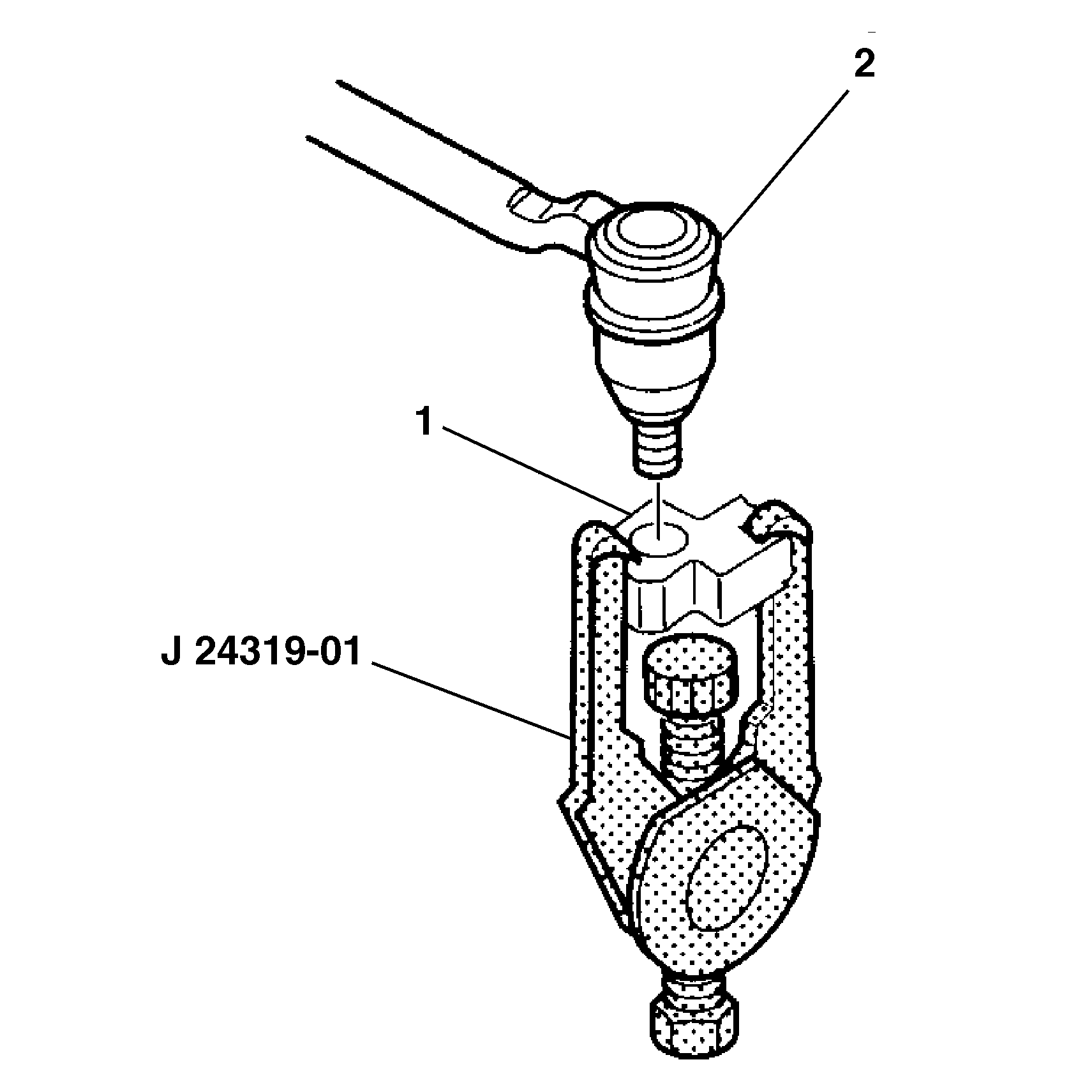
| • | J 24319-01 Universal Steering Linkage Puller |
| • | J 39549 Ball Joint/Tie Rod Separator |
- Raise and suitably support the vehicle. Refer to Lifting and Jacking the Vehicle in General Information.
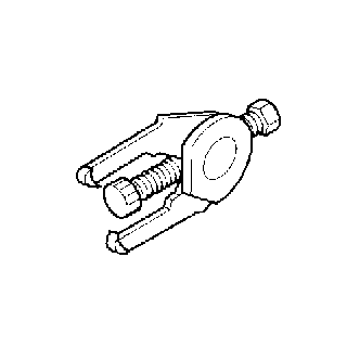
- Remove the stabilizer shaft link. Refer to Stabilizer Shaft Link Replacement .
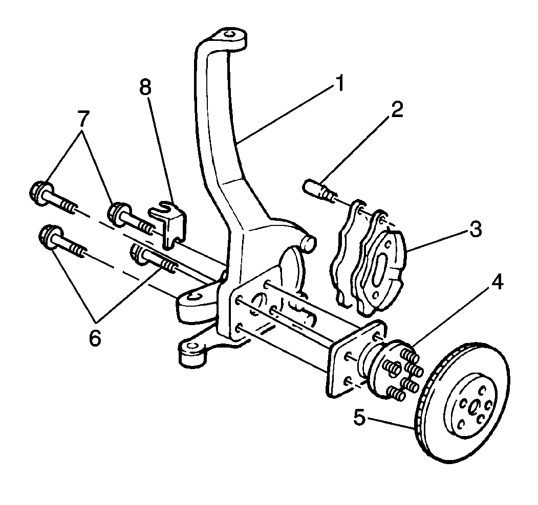
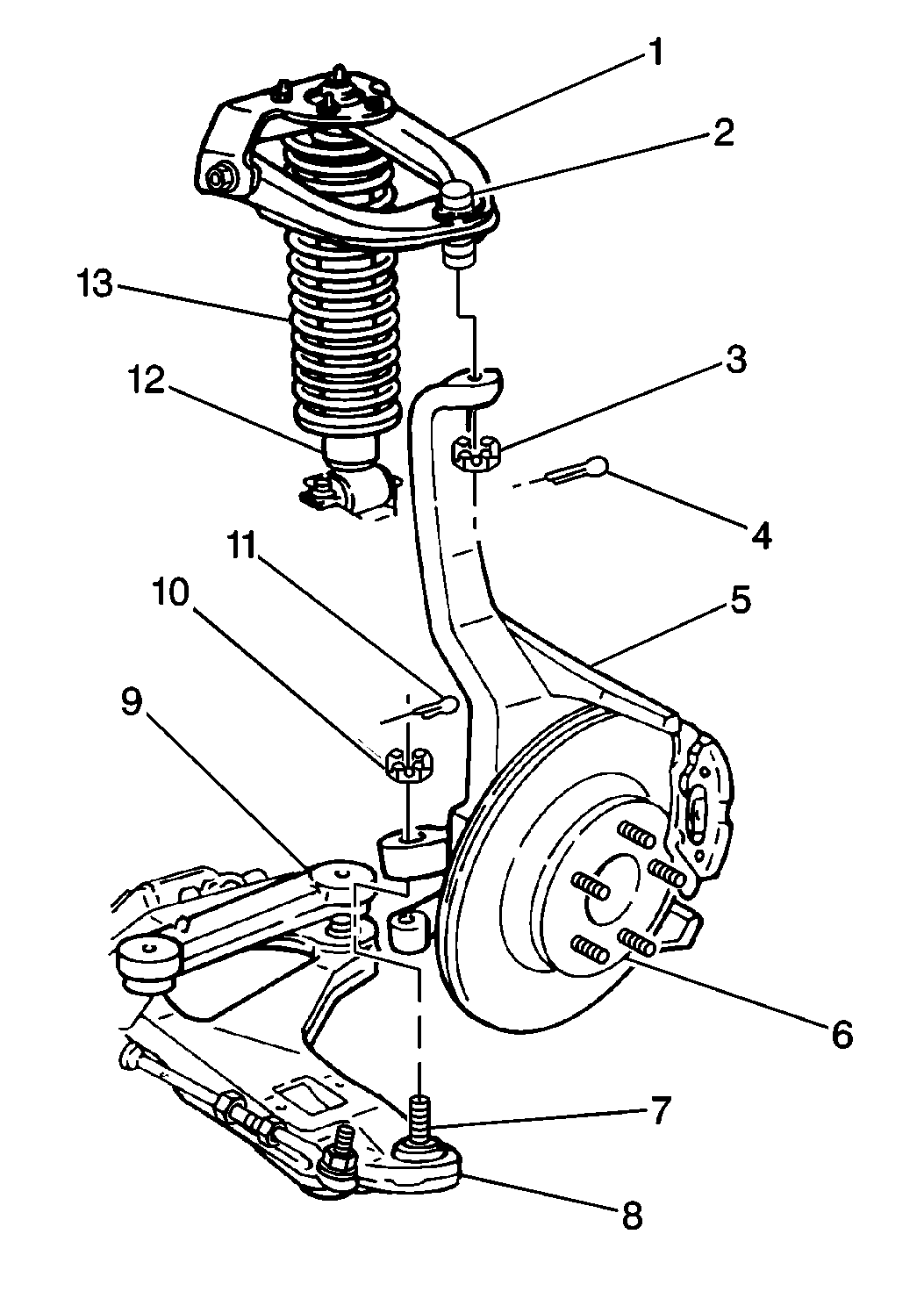
- Remove the wheel hub (4) from the steering knuckle (1). Refer to Front Wheel Bearing and Hub Replacement .
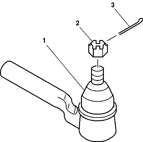
- Remove and discard the cotter pin (3) from the outer tie rod end (1).
- Remove the outer tie rod end nut (2).
- Using J 24319-01 separate the outer tie rod end (2) from the steering knuckle (1).
- Use a jack stand to support the lower control arm.
- Remove the shock absorber lower bolts and nuts.
- Remove and discard the upper control arm cotter pin.
- Remove the upper control arm nut.
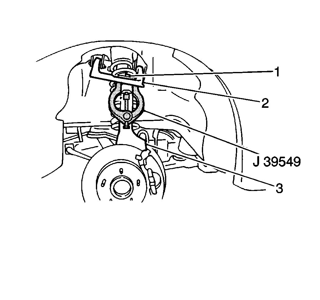
- Using J 39549 separate the upper ball joint (1) from the steering knuckle (3).
- Remove the upper control arm (2) and upper ball joint (1) from the steering knuckle (3).
- Remove and discard the lower control arm cotter pin.
- Remove the lower control arm nut.
- Using J 39549 separate the lower ball joint (7) from the steering knuckle (5).
- Remove the lower control arm (8) and lower ball joint (7) from the steering knuckle (5).
- Remove the steering knuckle (5) from the vehicle.
Installation Procedure
- Install the steering knuckle (5) to the vehicle.
- Align and Install the lower ball joint (7) and control arm (8) to the steering knuckle (5).
- Install the lower control arm nut.
- Install a new lower control arm cotter pin.
- Align and install the upper control arm and upper ball joint to the steering knuckle.
- Install the upper control arm nut.
- Install a new upper control arm cotter pin.
- Install the shock absorber lower bolts and nuts.
- Remove the jack stand supporting the lower control arm.
- Connect the outer tie rod end (2) to the steering knuckle (1).
- Install the outer tie rod end nut (2).
- Install a new cotter pin (3) to the outer tie rod end (1).
- Install the wheel hub (4) from the steering knuckle (1). Refer to Front Wheel Bearing and Hub Replacement .
- Install the stabilizer shaft link. Refer to Stabilizer Shaft Link Replacement .
- Lower the vehicle.
- Check the wheel toe-in. Refer to Front Toe Adjustment in Wheel Alignment.
Tighten
Tighten the lower control arm nut to 110 N·m (81 lb ft).
Important: Never loosen the control arm nut in order to align the cotter pin solt, it is permissible to over torque the control arm nut 1/6 of a turn MAX.
Tighten
Tighten the upper control arm nut to 53 N·m (39 lb ft).
Tighten
Tighten the shock absorber lower bolts or nuts to 65 N·m
(48 lb ft).
Tighten
Tighten the outer tie rod end nut (2) to 47 N·m (35 lb ft).
