For 1990-2009 cars only
Removal Procedure
- Raise and suitably support the vehicle. Refer to Lifting and Jacking the Vehicle in General Information.
- Remove the tire and wheel. Refer to Tire and Wheel Removal and Installation in Tires and Wheels.
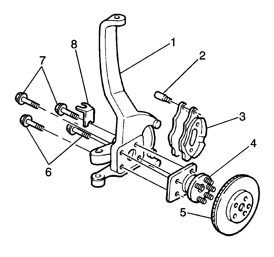
- Remove the brake caliper (3) from its mounting.
- Support the brake caliper (3) on the steering knuckle using mechanics wire.
- Remove the brake rotor (5) from the wheel bearing hub (4).
- Disconnect the wheel speed sensor electrical connector.
- Remove the wheel bearing hub bolts (6 and 7) and wheel speed sensor wire bracket (8).
- Pull the wheel bearing hub (4) from the steering knuckle (1).
If the hub is difficult to remove, use a slide hammer and adapter attached to the wheel studs.
Installation Procedure
- Align the wheel bearing hub (4) to the steering knuckle (1).
- Install the wheel bearing hub bolts (6 and 7) and wheel speed sensor wire bracket (8).
- Connect the wheel speed sensor electrical connector. Attach the wheel speed sensor wire to the bracket (8).
- Install the brake rotor (5) to the wheel bearing hub (4).
- Remove the brake caliper (3) from the mechanics wire support.
- Install the brake caliper (3) to its mounting.
- Install the tire and the wheel. Refer to Tire and Wheel Removal and Installation in Tires and Wheels.
- Lower the vehicle.
Notice: Refer to Fastener Notice in the Preface section.
Tighten
Tighten the wheel bearing hub bolts (6 and 7) to 86 N·m (63 lb ft).
