For 1990-2009 cars only
Transmission Replacement Transaxle Assembly
Removal Procedure
Tools Required
J 28467-360 Engine Support Fixture
- Disconnect the negative battery cable.
- Install the J 28467-360 . Refer to Engine Support Fixture .
- Remove the front transmission mount bolts. Refer to Transmission Front Mount Replacement .
- Remove the left splash shield. Refer to Wheelhouse Splash Shield Replacement in Body Front End.
- Remove the air cleaner and duct assembly from the throttle body. Refer to Air Cleaner Assembly Replacement in Engine Controls - 2.4L.
- Remove the wire harness from the upper transaxle mount bracket.
- Remove the side transaxle mount. Refer to Transmission Mount Replacement - Side .
- Remove the shifter cable. Refer to Transmission Control Replacement .
- Secure the vehicle radiator and condenser to the upper radiator support.
- Remove the ground cables from the engine block.
- Disconnect the park neutral position (PNP) switch connector.
- Raise and support the vehicle. Refer to Lifting and Jacking the Vehicle in General Information.
- Support the vehicle with a safety stand.
- Drain the transaxle. Refer to Oil Pan Replacement .
- Remove the front tire and wheel assemblies. Refer to Wheel Removal in Tires and Wheels.
- Remove the lower radiator and condenser support.
- Remove the front transmission mount bracket bolts and bracket. Refer to Transmission Front Mount Replacement .
- Remove the front Antilock Brake System (ABS) Wheel Speed Sensor (WSS) connectors.
- Unroute the ABS WSS harness.
- Remove the brake modulator assembly bolts and the brake modulator assembly. Refer to Electronic Brake Control Module Replacement in Antilock Brake System.
- Remove the vehicle speed sensor.
- Remove the torque converter bolts. Refer to Flywheel to Torque Converter Bolt Replacement .
- Remove the left and right ball joint nuts.
- Separate the ball joint from the control arm. Refer to Lower Control Arm Ball Joint Replacement in Front Suspension.
- Remove the drive axles. Refer to Wheel Drive Shaft Replacement in Wheel Drive Shafts.
- Separate the tie rod ends from the steering knuckles. Refer to Rack and Pinion Outer Tie Rod End Replacement in Power Steering System.
- Disconnect the power steering pressure line from the rack and pinion. Refer to Power Steering Pressure Pipe/Hose Replacement in Power Steering System.
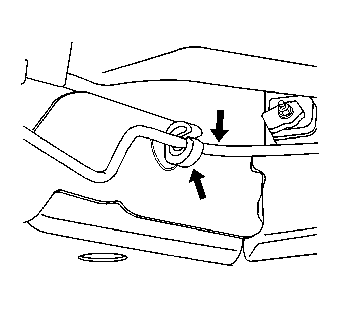
- Remove the brake lines from the retainer below the rack and pinion.
- Remove the steering column pinch bolt and position the intermediate shaft aside. Refer to Intermediate Steering Shaft Replacement in Steering Wheel and Column - Tilt.
- Attach the transaxle case to the support stand.
- Remove the transaxle-to-engine mount bolts.
- Remove the transaxle:
- Unroute the ABS WSS harness.
Caution: Unless directed otherwise, the ignition and start switch must be in the OFF or LOCK position, and all electrical loads must be OFF before servicing any electrical component. Disconnect the negative battery cable to prevent an electrical spark should a tool or equipment come in contact with an exposed electrical terminal. Failure to follow these precautions may result in personal injury and/or damage to the vehicle or its components.
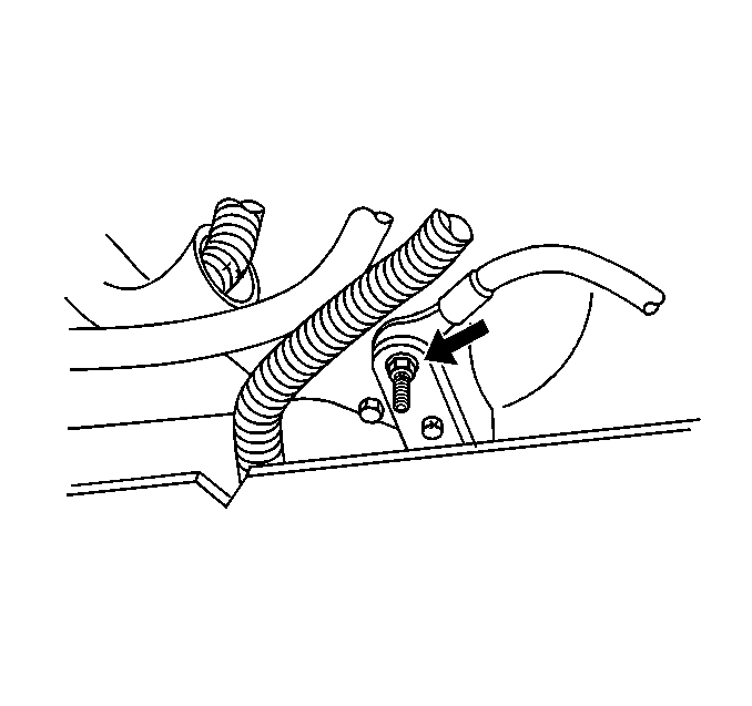
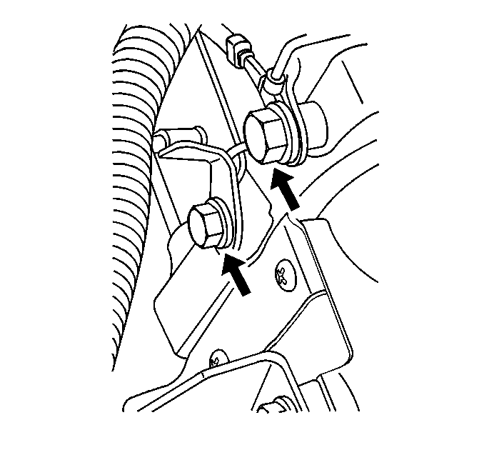
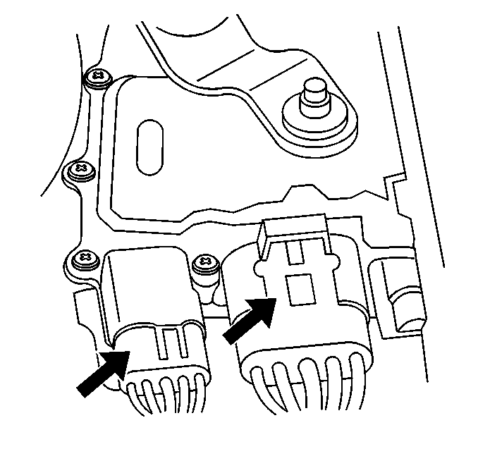
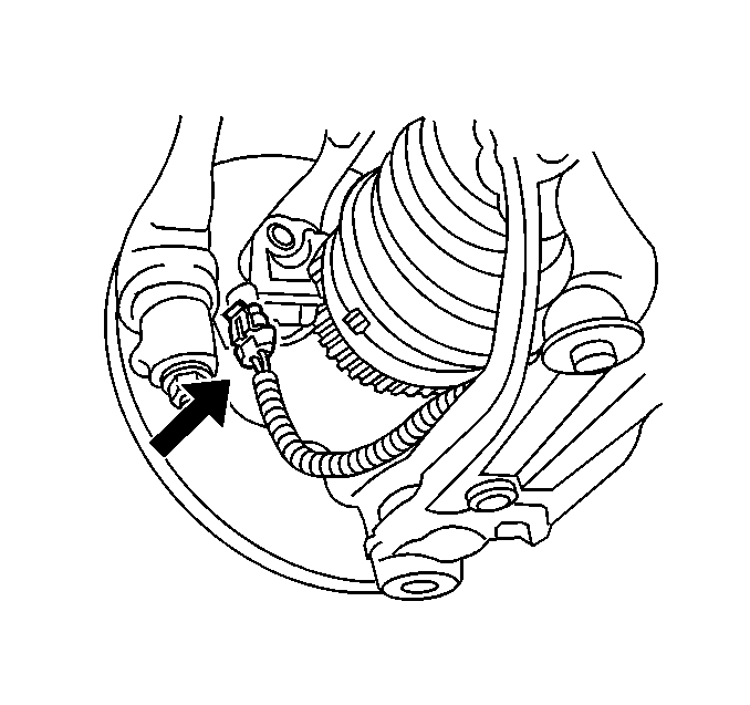
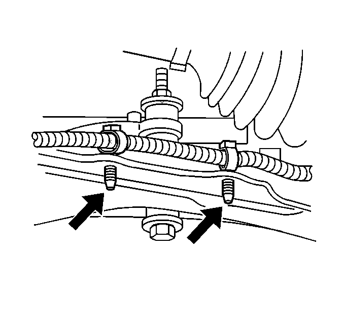
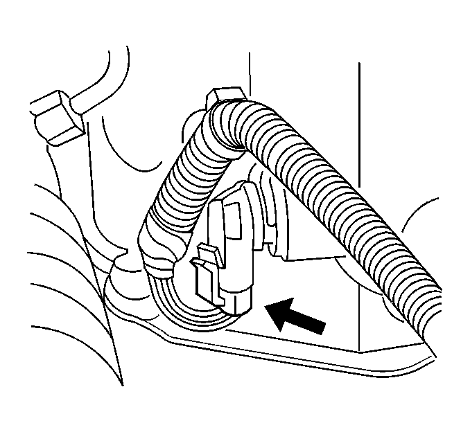
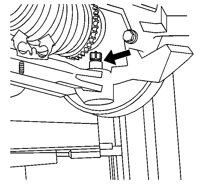
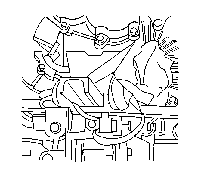
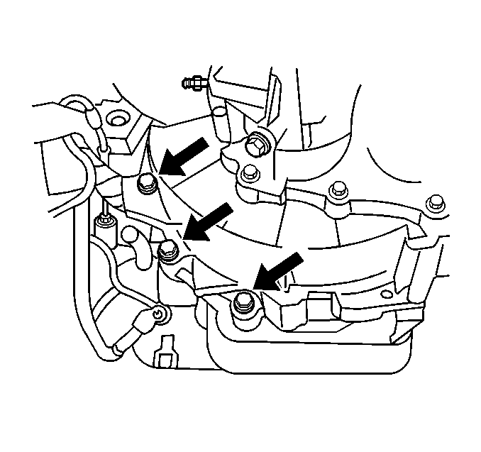
| 32.1. | Slide the transaxle away from the engine. |
| 32.2. | Carefully lower the support stand. |

Installation Procedure
- Install the transaxle:
- Install the transaxle-to-engine mount bolts.
- Detach the transaxle case from the support stand.
- Install the steering column pinch bolt and position the intermediate shaft. Refer to Intermediate Steering Shaft Replacement in Steering Wheel and Column - Tilt.
- Install the brake lines to the retainer below the rack and pinion.
- Connect the power steering pressure line to the rack and pinion. Refer to Power Steering Pressure Pipe/Hose Replacement in Power Steering System.
- Install the tie rod ends to the steering knuckles. Refer to Rack and Pinion Outer Tie Rod End Replacement in Power Steering System.
- Install the ABS module. Refer to Electronic Brake Control Module Replacement in Antilock Brake System.
- Install the front transaxle mount. Refer to Transmission Front Mount Replacement .
- Install the drive axles. Refer to Wheel Drive Shaft Replacement in Wheel Drive Shafts.
- Install the ball joint to the control arm. Refer to Lower Control Arm Ball Joint Replacement in Front Suspension.
- Install the left and right ball joint nuts.
- Install the torque converter bolts. Refer to Flywheel to Torque Converter Bolt Replacement .
- Install the vehicle speed sensor.
- Install the oil pan. Refer to Oil Pan Replacement .
- Install the front Antilock Brake System (ABS) Wheel Speed Sensor (WSS) connectors.
- Install the front transmission mount bracket bolts and bracket. Refer to Transmission Front Mount Replacement .
- Install the lower radiator and condenser support.
- Install the left front inner splash shield. Refer to Wheelhouse Splash Shield Replacement in Body Front End.
- Install the front tire and wheel assemblies. Refer to Wheel Installation in Tires and Wheels.
- Fill the transaxle. Refer to Oil Pan Replacement .
- Support the vehicle with a safety stand.
- Lower the vehicle.
- Connect the PNP switch connector.
- Install the ground cables from the engine block.
- Secure the vehicle radiator and condenser to the upper radiator support.
- Install the shifter cable. Refer to Transmission Control Replacement .
- Install the wire harness from the upper transaxle mount bracket.
- Install the air cleaner and duct assembly to the throttle body. Refer to Air Cleaner Assembly Replacement .
- Install the splash shield. Refer to Wheelhouse Splash Shield Replacement in Body Front End.
- Lower the vehicle.
- Fill the transmission with Mercon III® to the recommended levels.
- Remove the J 28467-360 . Refer to Engine Support Fixture .
- Connect the negative battery cable.
- Start the engine.
- Inspect the transmission for leaks.
- Inspect the transmission fluid level. Refer to Transmission Fluid Check .
| 1.1. | Slide the transaxle towards the engine. |
| 1.2. | Carefully raise the support stand. |




Transmission Replacement Parts, Cleaning, Inspection
Cleaning Procedure
- Use appropriate safety equipment such as:
- Keep the work area and tools clean.
- Clean the transmission exterior before removing parts.
- Do not use wipe cloths or rags.
- Do not use solvents on the following:
- Blow out all passages with compressed air.
- Clean out small passages with fine wire.
- Handle parts carefully in order to prevent damage.
- Lubricate all internal parts with transmission oil during assembly.
- When installing screws, bolts or studs into aluminum, always dip the threads in transmission oil. Use adhesive/sealant on threads where indicated.
- Always use a torque wrench for proper torque.
- Recondition damaged or stripped aluminum threads with thread inserts.
- Replace all gaskets and O-ring seals.
- Do not use gasket cement or sealers.
- Replace PTFE (Teflon®) and rubber lip seals unless the unit is new.
Notice: Do not use air powered tools in order to disassemble or assemble any vehicle component. Bolt torques are vital to diagnosis. You can detect bolt torques only when using hand tools. Improper bolt torques can contribute to vehicle repair problems.
| • | Safety glasses. |
| • | Safety shoes. |
| • | Gloves. |
| • | Rubber seals. |
| • | Plastic/PTFE (Teflon®) thrust washers. |
Inspection Procedure
- Inspect the manual linkage for the following:
- Inspect all seals, gaskets, O-rings, and mating surfaces for the following:
- Inspect the snap rings for the following:
- Inspect bearings and thrust surfaces for the following:
| • | Wear at pivoting points. |
| • | Bent or broken links and rods. |
| • | Nicks. |
| • | Cuts. |
| • | Damage. |
| • | Expansion or compression. |
| • | Distortion. |
| • | Nicks. |
| • | Proper ring to groove fit. |
| • | Wear. |
| • | Scoring. |
| • | Pitting. |
