For 1990-2009 cars only
Removal Procedure
- Disable the SIR system. Refer to SIR Disabling and Enabling .
- Disconnect the negative battery cable. Refer to Battery Negative Cable Disconnection and Connection .
- Remove the engine assembly. Refer to Engine Replacement or Engine Replacement .
- Remove the negative cable from the engine bay. Refer to Battery Negative Cable Replacement .
- Remove the positive cable from the engine bay. Refer to Battery Positive Cable Replacement .
- Raise and support the vehicle. Refer to Lifting and Jacking the Vehicle .
- Remove the front wheels. Refer to Tire and Wheel Removal and Installation .
- Remove the front wheelhouse liner. Refer to Front Wheelhouse Liner Replacement .
- Remove the front wheel hub assembly. Refer to Front Wheel Bearing and Hub Replacement .
- Remove the front strut assembly. Refer to Strut Assembly Replacement .
- Lower the vehicle.
- Remove the brake lines. Refer to Brake Pipe Replacement .
- Remove the fender assembly. Refer to Front Fender Replacement .
- Remove the front fascia. Refer to Front Bumper Fascia Replacement .
- Remove the coolant reservoir. Refer to Coolant Recovery Reservoir Replacement .
- Remove the front end module. Refer to Front End Panel Module Carrier Assembly Replacement .
- Remove the air inlet grille. Refer to Air Inlet Grille Panel Replacement .
- Remove the plenum chamber. Refer to Air Inlet Assembly Replacement .
- Remove the relay box. Refer to Underhood Electrical Center or Junction Block Replacement .
- Remove the ABS unit. Refer to Brake Pressure Modulator Valve Assembly Replacement .
- Remove the brake master cylinder. Refer to Master Cylinder Replacement .
- Note the location and remove the sealers and anti-corrosion materials from the repair area, as necessary. Refer to Anti-Corrosion Treatment and Repair .
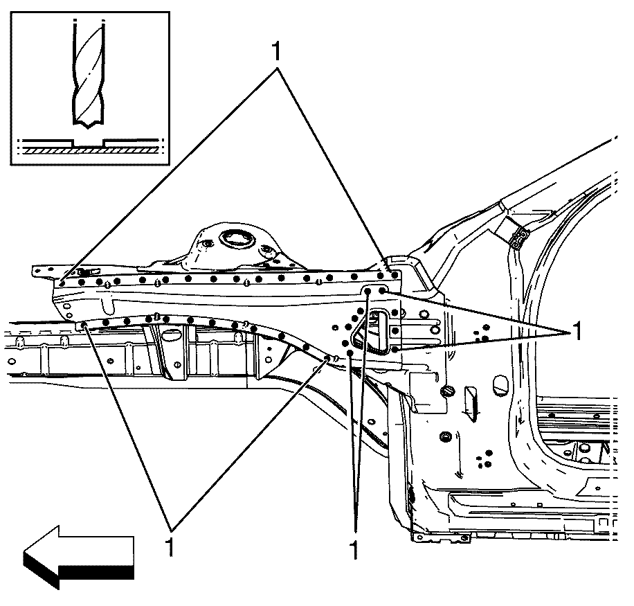
- Locate, mark and drill out the factory welds (1) attaching the upper wheelhouse brace to the front wheelhouse assembly.
- Remove the upper wheelhouse brace from the front wheelhouse assembly and discard.
Caution: Refer to Approved Equipment for Collision Repair Caution in the Preface section.
Caution: Refer to Vehicle Lifting Caution in the Preface section.
Caution: Refer to Safety Glasses Caution in the Preface section.
Caution: Refer to Foam Sound Deadeners Caution in the Preface section.

Discard the upper wheelhouse brace.
Installation Procedure
- Drill 8 mm (5/16 in) plug weld holes as necessary in the locations noted from the original assembly.
- Clean and prepare the mating surfaces of the front wheelhouse assembly and the upper wheelhouse brace.
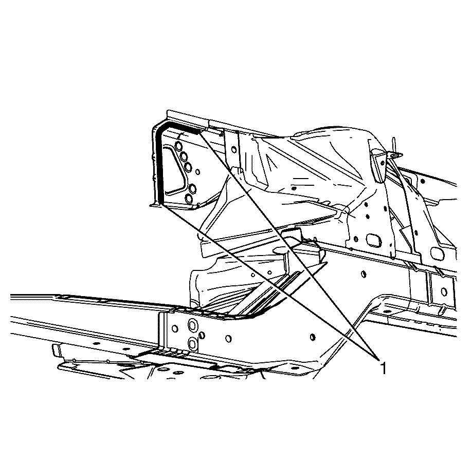
- Apply the primary sealer (1) HN2484 along the rear edge of the upper wheelhouse brace.
- Position the upper wheelhouse brace on the vehicle. Verify correct alignment and position using three-dimensional measuring equipment.
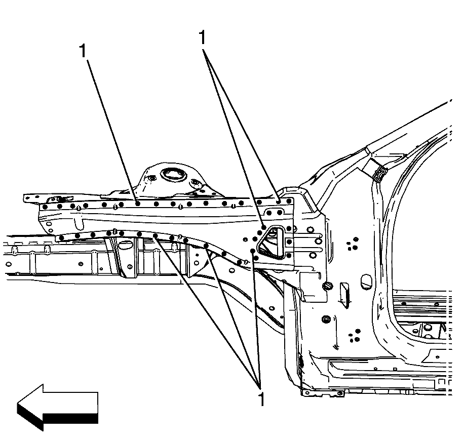
- Puddle weld (1) the front wheelhouse assembly to the upper wheelhouse brace.
- Apply the sealers and anti-corrosion materials to the repair area, as necessary. Refer to Anti-Corrosion Treatment and Repair .
- Paint the repaired area. Refer to Basecoat/Clearcoat Paint Systems .
- Install the brake master cylinder. Refer to Master Cylinder Replacement .
- Install the ABS unit. Refer to Brake Pressure Modulator Valve Assembly Replacement .
- If re-programming is required. Refer to Control Module References .
- Install the relay box. Refer to Underhood Electrical Center or Junction Block Replacement .
- Install the plenum chamber. Refer to Air Inlet Assembly Replacement .
- Remove the air inlet grille. Refer to Air Inlet Grille Panel Replacement .
- Install the relay box. Refer to Underhood Electrical Center or Junction Block Replacement .
- Install the plenum chamber. Refer to Air Inlet Assembly Replacement .
- Remove the air inlet grille. Refer to Air Inlet Grille Panel Replacement .
- Install the front end module. Refer to Front End Panel Module Carrier Assembly Replacement .
- Install the brake lines. Refer to Brake Pipe Replacement .
- Raise and support the vehicle. Refer to Lifting and Jacking the Vehicle .
- Install the coolant reservoir. Refer to Coolant Recovery Reservoir Replacement .
- Install the front fascia. Refer to Front Bumper Fascia Replacement .
- Install the front strut assembly. Refer to Strut Assembly Replacement .
- Install the front wheel hub assembly. Refer to Front Wheel Bearing and Hub Replacement .
- Install the front wheel house liner. Refer to Front Wheelhouse Liner Replacement .
- Install the front wheels. Refer to Tire and Wheel Removal and Installation .
- Lower the vehicle.
- Install the fender assembly. Refer to Front Fender Replacement .
- Install the engine assembly. Refer to Engine Replacement or Engine Replacement .
- Connect the negative battery cable. Refer to Battery Negative Cable Disconnection and Connection .
- Enable the SIR system. Refer to SIR Disabling and Enabling .
- If re-programming is required. Refer to Control Module References .
Important: Spot welding is the preferred method for attaching panels and should be used wherever possible. A plug weld should be performed where your spot welder is unable reach.
Important: If the location of the original plug weld holes can not be determined, or if structural weld-thru adhesive is present, space the plug weld holes every 32 mm (1¼ in).


