Master Cylinder Replacement 2.4L Engine
Special Tools
J-37767 Brake Booster Piston Rod Adjuster
Removal Procedure
- With the engine OFF, press the brake pedal several times in order to remove the vacuum from the brake booster.
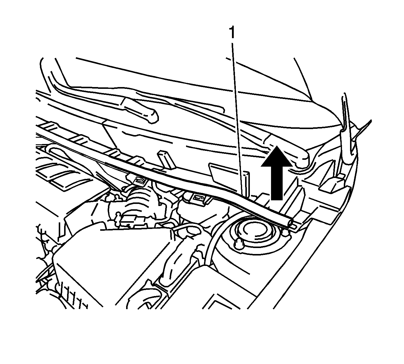
- Slide the hood rear seal (1) to the right and up in order to disengage the clip.
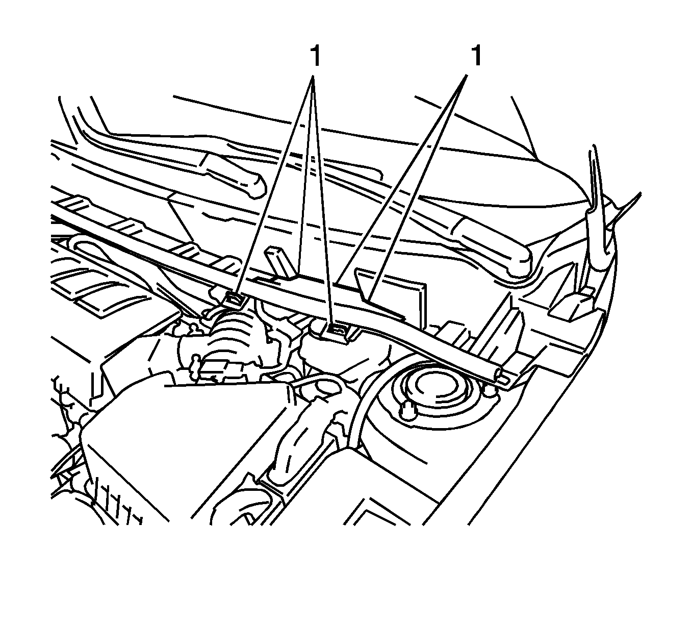
- Disengage the 5 claws (1) and remove the left side access panel.
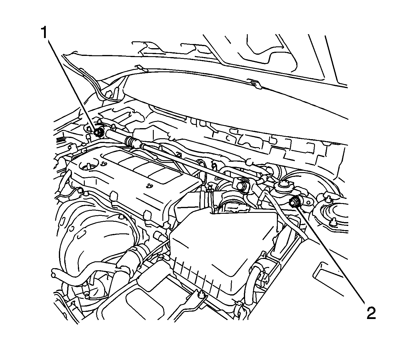
- Remove the 2 nuts (1, 2).
- Remove the damper and the tie bar.
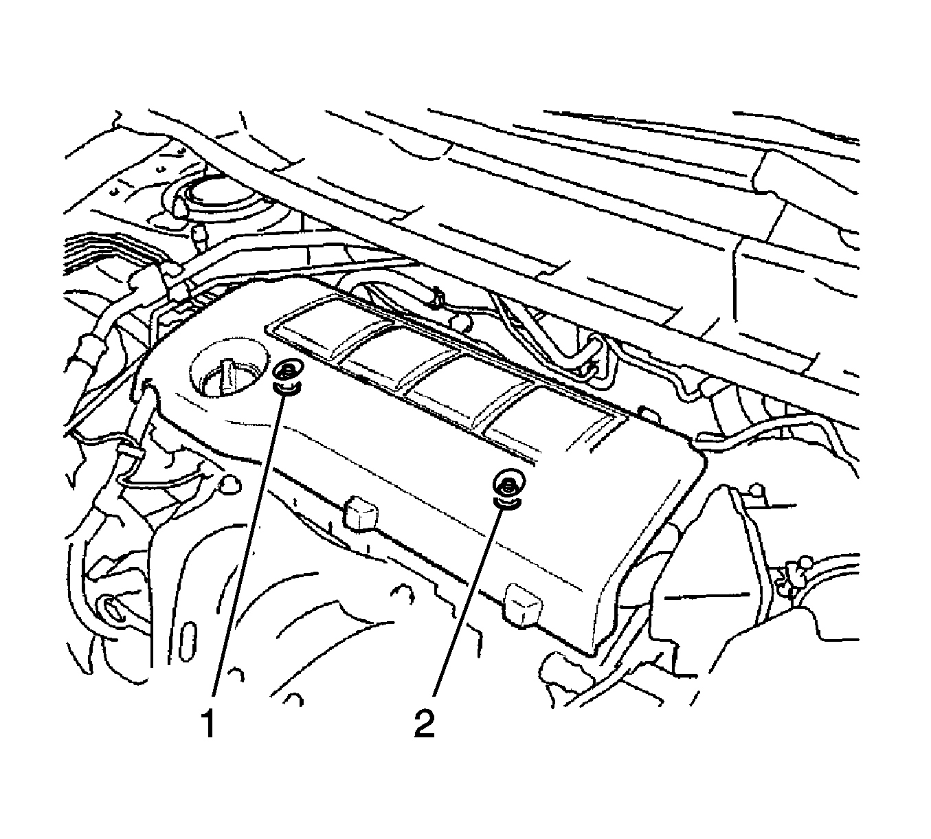
- Remove the 2 nuts (1, 2) and the engine cover.
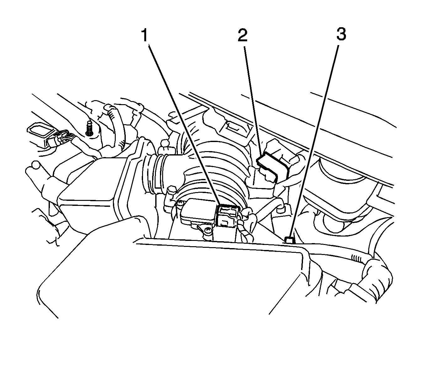
- Disconnect the mass air flow meter connector (1).
- Separate the 2 wire harness clamps (2, 3).
- Disconnect the vacuum switching valve connector (3).
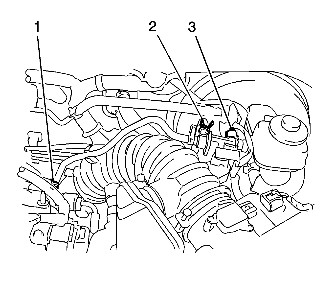
- Loosen the 2 hose clamps (1, 2) and disconnect the vacuum hose.
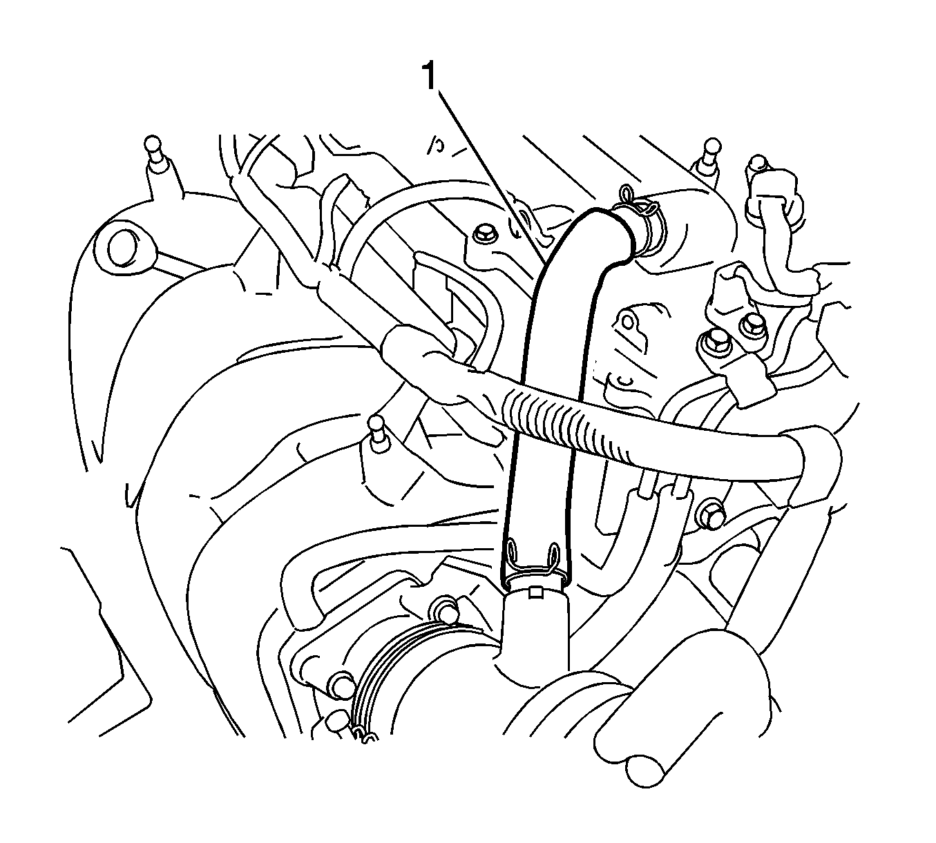
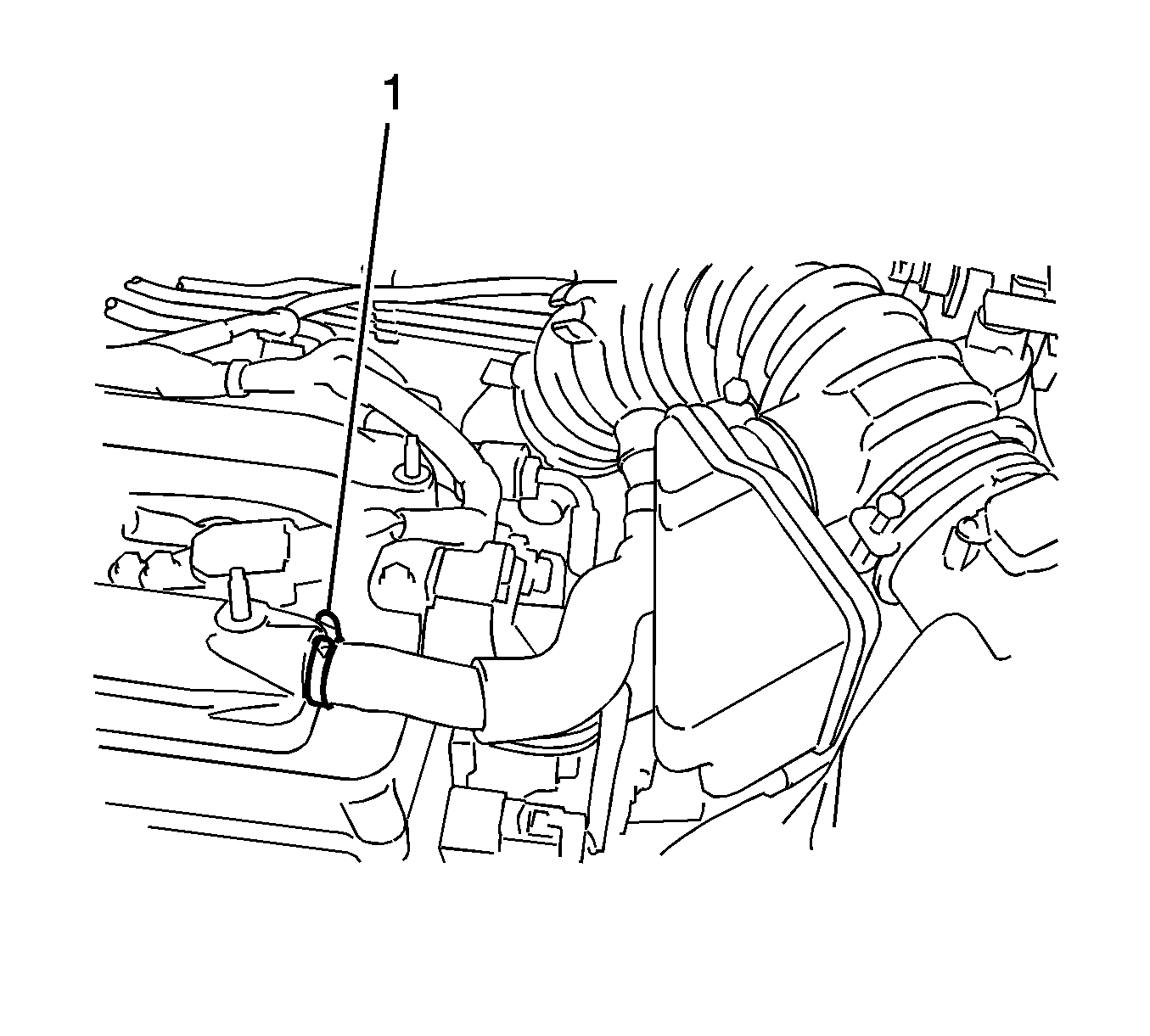
- Loosen the hose clamp (1) and disconnect the ventilation hose.
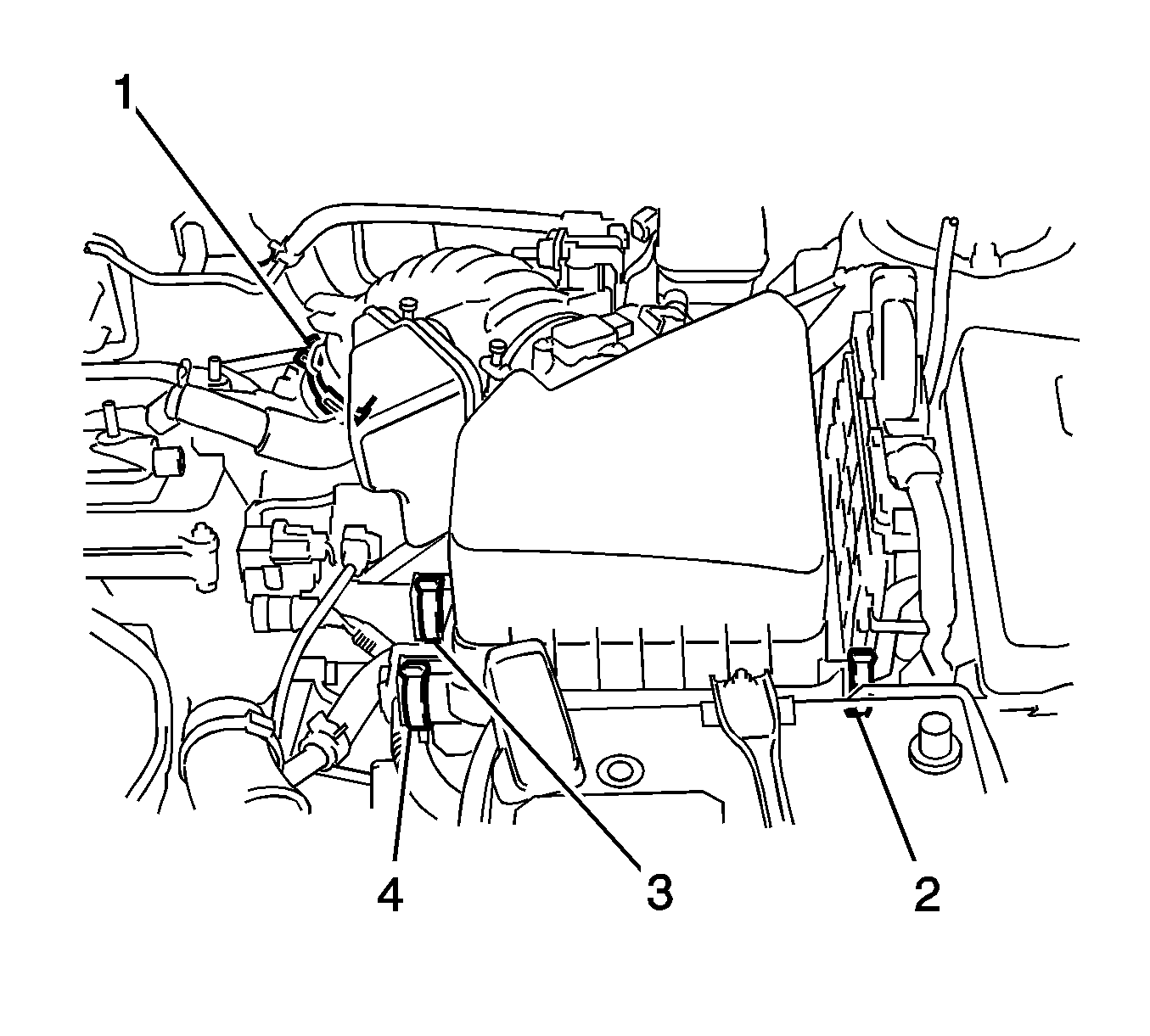
- Unlock the 3 air cleaner case clamps (2, 3, 4).
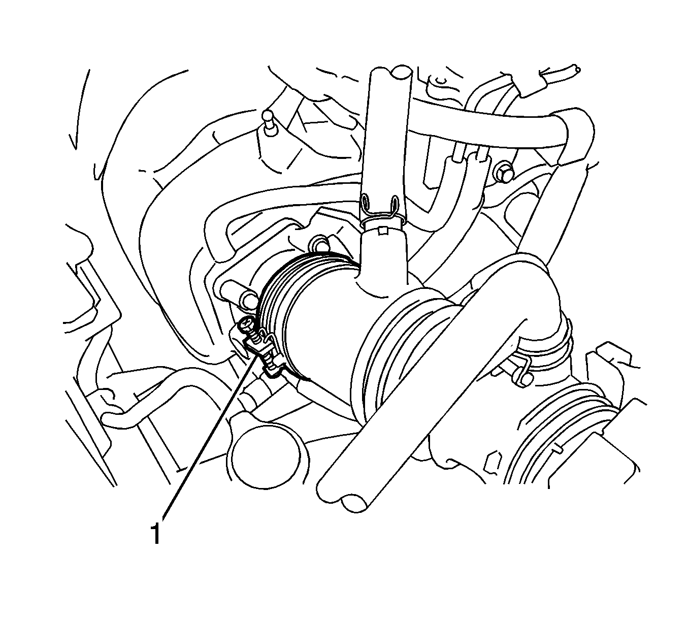
- Loosen the air cleaner hose clamp (1).
- Remove the upper portion of the air cleaner case with the hose.
- Cover the air cleaner filter element in order to protect the filter from spills.
- Remove the cap from the brake fluid reservoir.
- Remove the filter from the reservoir.
- Siphon the brake fluid from the reservoir.
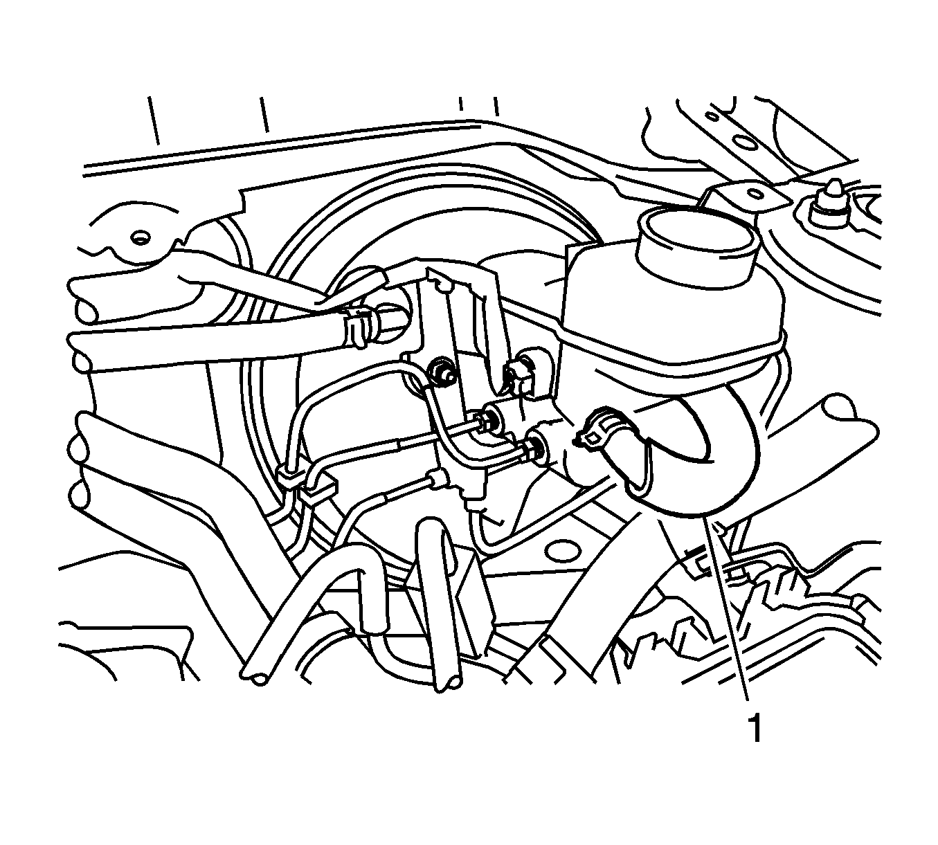
- If the vehicle has a manual transmission, loosen the clamp and remove the clutch tube (1) from the reservoir.
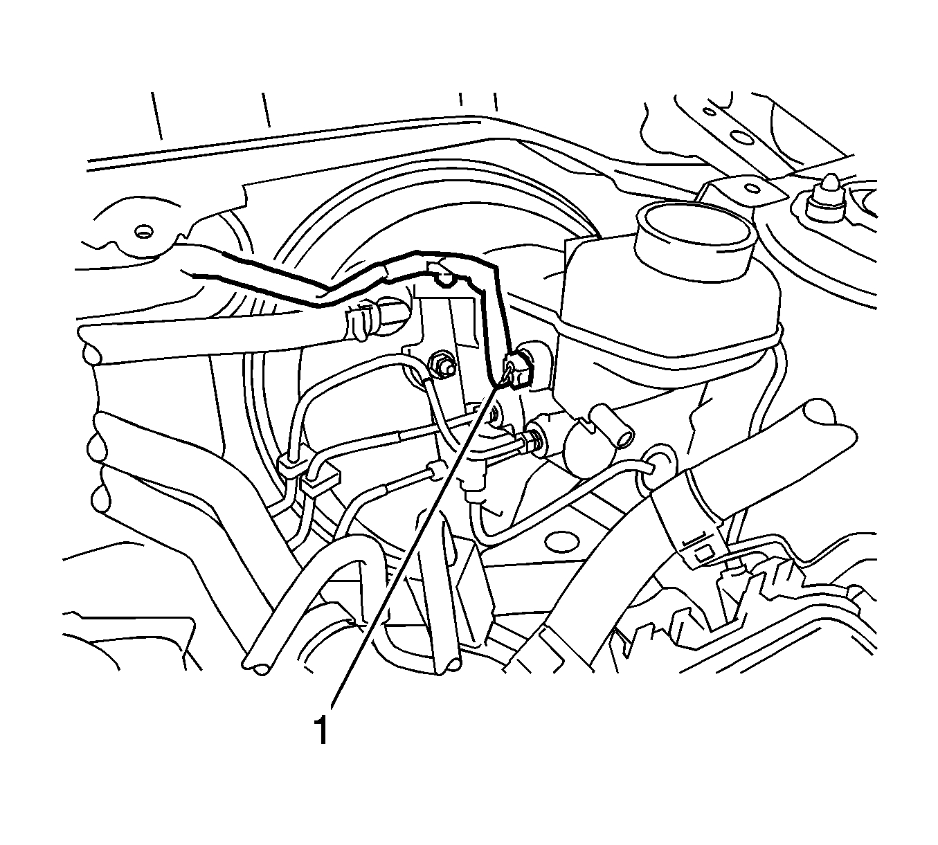
- Disconnect the connector (1) from the brake fluid level sensor.
- Disengage the clamp from the brake fluid level sensor wire.
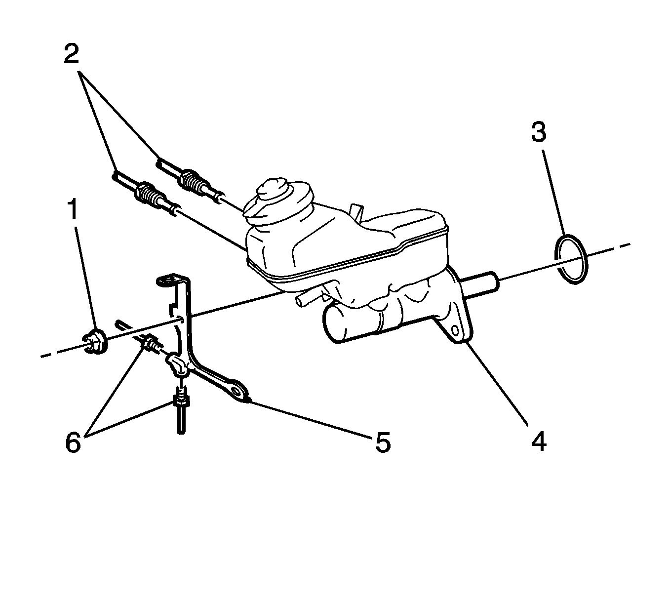
- Remove the 2 brake pipes (2) from the master cylinder (4).
- Remove the 2 brake pipes (6) from the 2-way fitting (5).
- Remove the 2 nuts (1) from the 2-way fitting.
- Remove the 2-way fitting from the master cylinder.
- Remove the master cylinder with the reservoir from the vacuum brake booster.
- Remove the seal (3) from the master cylinder.
- Remove the reservoir and the grommets from the master cylinder. Refer to Master Cylinder Reservoir Replacement.
Warning: Refer to Brake Fluid Irritant Warning in the Preface section.
Caution: Refer to Brake Fluid Effects on Paint and Electrical Components Caution in the Preface section.
Note: Hold the master cylinder with the piston facing upward in order to prevent the piston from sliding out.
Inspection Procedure
- Apply chalk to the tip of the accessory tool (1).
- Measure the clearance between the brake booster push rod and the accessory tool.
- If the clearance between the brake booster push rod and the accessory tool is not correct, adjust the length of the brake booster push rod.
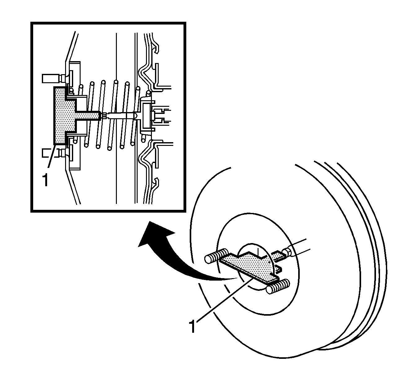
Note: The accessory tool comes with a new master cylinder. If you are installing a new master cylinder, inspect the master cylinder piston-to-vacuum brake booster push rod clearance. If you are reusing the original master cylinder, an inspection is not necessary, even with a new brake booster.
If there is a clearance between the accessory tool and the shell of the brake booster, the brake booster push rod is protruding too far.
If the chalk does not stick to the tip of the brake booster push rod, the brake booster push rod is not protruding far enough.
Adjustment Procedure
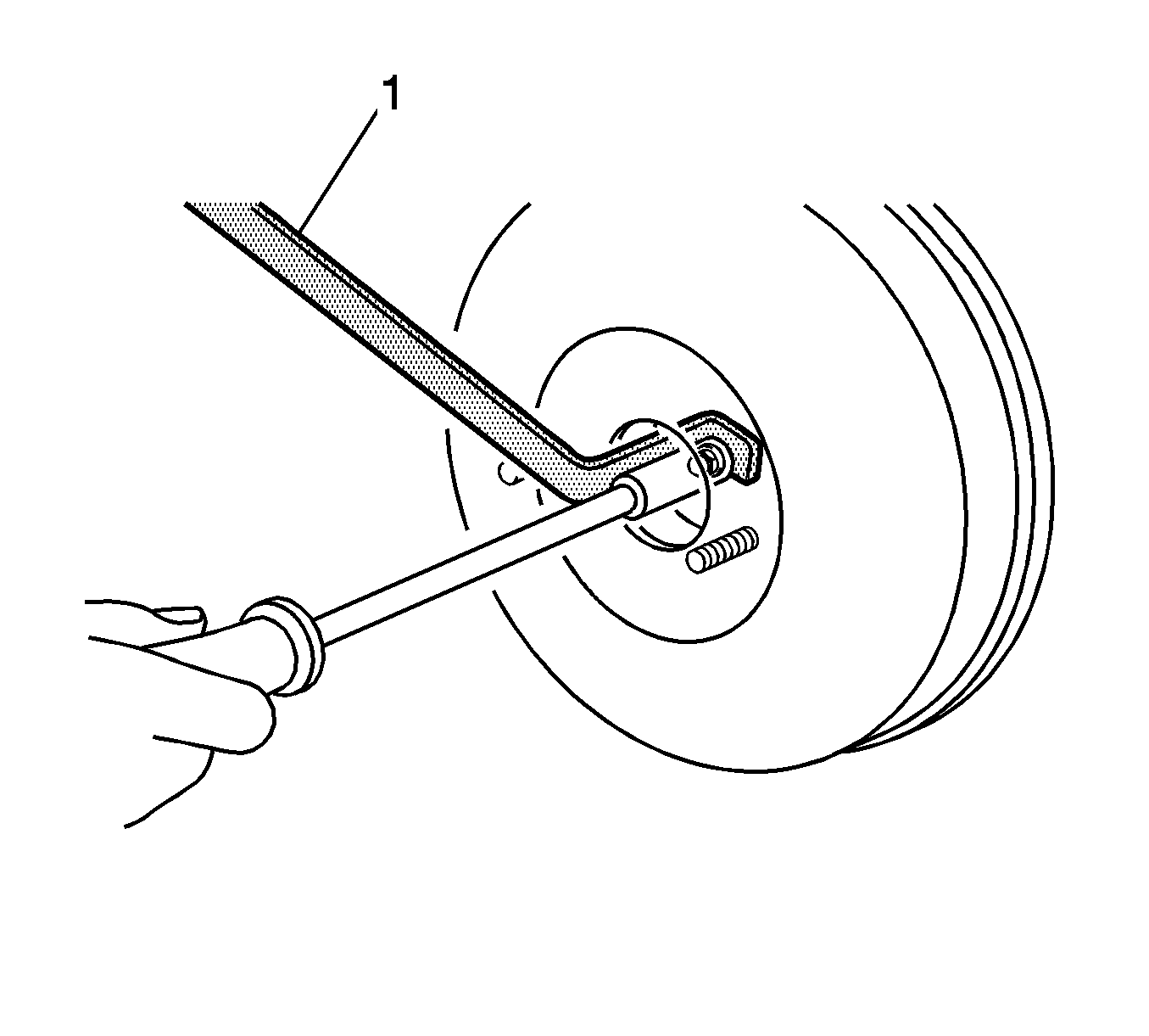
Hold the brake booster push rod with the J-37767 Adjuster (1) and turn the tip of the rod with a socket driver in order to adjust the length of the rod.
Installation Procedure
- Install the reservoir and the grommets to the master cylinder. Refer to Master Cylinder Reservoir Replacement.
- Bench bleed the master cylinder. Refer to Master Cylinder Bench Bleeding.
- Install the seal (3) to the master cylinder (4).
- Ensure the master cylinder piston is covered with lithium soap base glycol grease, not dirt or any foreign objects.
- Install the master cylinder to the vacuum brake booster.
- Install the 2-way fitting (5) to the master cylinder.
- Install the 2 nuts (1) to the 2-way fitting and tighten to 13 N·m (115 lb in).
- Install the 2 brake pipes (6) to the 2-way fitting. Using a torque wrench with a fulcrum length of 250 mm (9.84 in) and a union nut wrench, tighten the fittings to 14 N·m (124 lb in).
- Install the 2 brake pipes (2) to the master cylinder. Using a torque wrench with a fulcrum length of 250 mm (9.84 in) and a union nut wrench, tighten the fittings to 14 N·m (124 lb in).
- Connect the connector (1) to the brake fluid level sensor.
- Engage the clamp on the brake fluid level sensor wire.
- If the vehicle has a manual transmission, install the clutch tube (1) with the clamp to the reservoir.
- Fill the brake fluid reservoir. Refer to Master Cylinder Reservoir Filling.
- If the vehicle has a manual transmission, bleed the clutch system. Refer to Hydraulic Clutch Bleeding.
- Bleed the entire hydraulic brake system. Refer to Hydraulic Brake System Bleeding.
- Inspect the brake system for leaks. Refer to Brake System External Leak Inspection.
- Remove the cover from the air cleaner filter element.
- Install the upper portion of the air cleaner case with the hose and the hose clamp (1).
- Lock the 3 clamps (2, 3, 4).
- Install the ventilation hose with the hose clamp (1).
- Install the vacuum hose with the 2 hose clamps (1, 2).
- Install the vacuum switching valve connector (3).
- Connect the mass air flow meter connector (1).
- Connect the 2 wire harness clamps (2, 3).
- Install the engine cover with the 2 nuts (1, 2) and tighten to 9 N·m (80 lb in).
- Install the damper and the tie bar to the brackets with the 2 nuts (1, 2) and tighten to 52 N·m (38 lb ft).
- Install the left side access panel and engage the 5 claws (1).
- Install the hood rear seal and engage the clip.
- Measure the brake pedal travel. Adjust the brake pedal travel if necessary. Refer to Brake Pedal Travel Measurement and Inspection.

Caution: Refer to Fastener Caution in the Preface section.


Warning: Refer to Brake Fluid Warning in the Preface section.
Caution: Refer to Filling the Master Cylinder Caution in the Preface section.


Master Cylinder Replacement 1.8L Engine
Special Tools
J-37767 Brake Booster Piston Rod Adjuster
Removal Procedure
- With the engine OFF, press the brake pedal several times in order to remove the vacuum from the brake booster.
- Slide the hood rear seal (1) to the right and up in order to disengage the clip.
- Disengage the 5 claws (1) and remove the left side access panel.
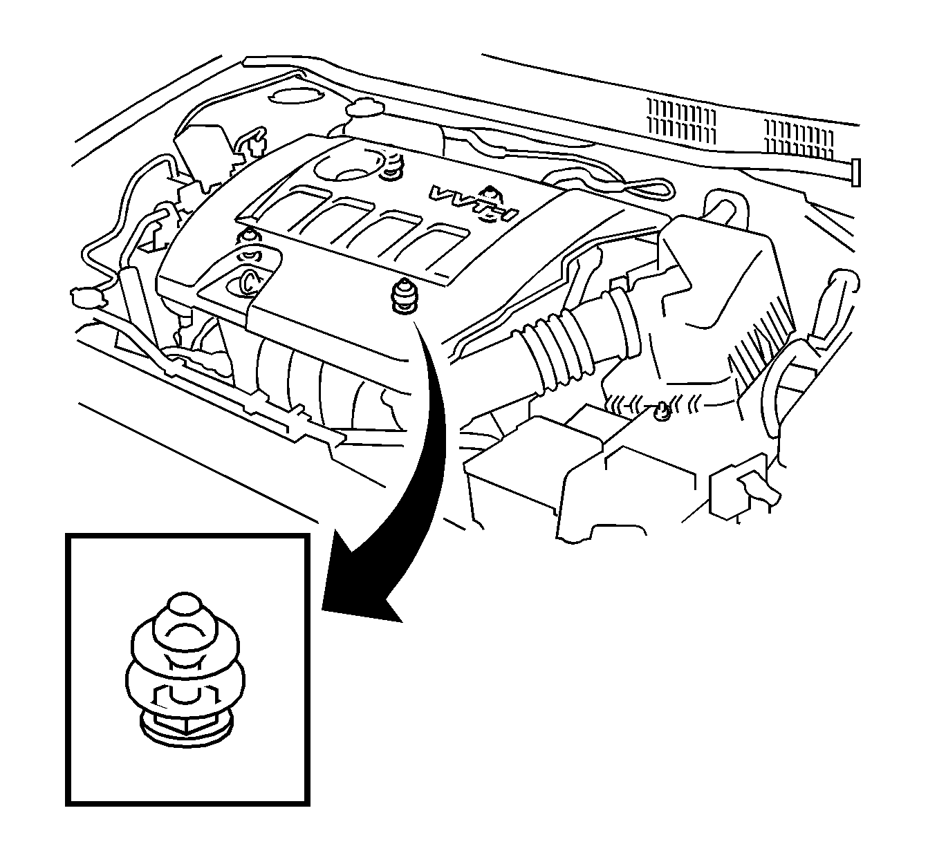
- Pull up on the rear edge of the engine cover in order to disengage the 2 rear clips.
- Pull up on the front edge of the engine cover, disengage the 2 front clips, and remove the engine cover.
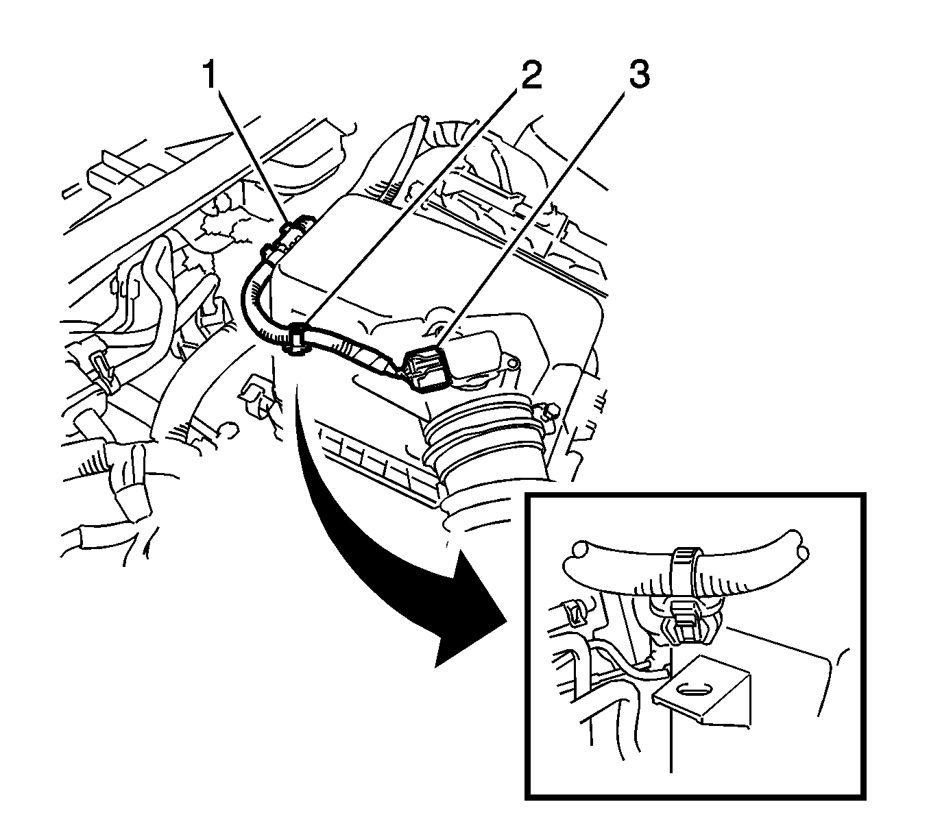
- Disconnect the mass air flow meter connector (3).
- Separate the 2 wire harness clamps (1, 2).
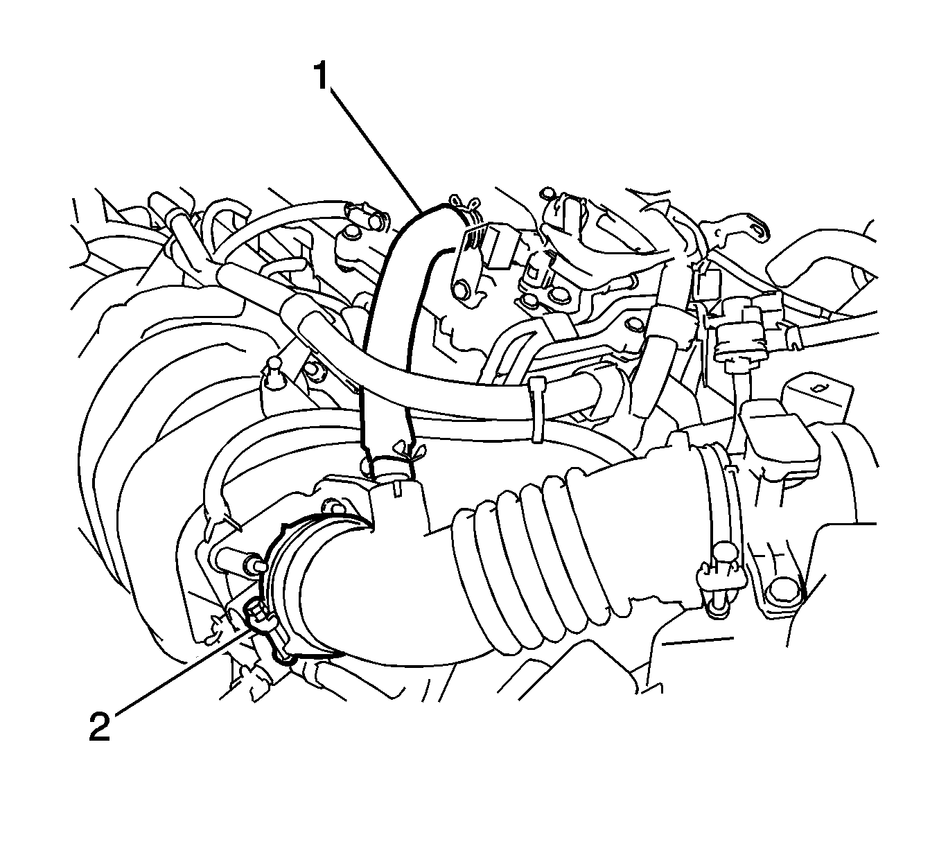
- Loosen the 2 hose clamps and disconnect the ventilation hose (1).
- Loosen the air cleaner hose clamp (2).
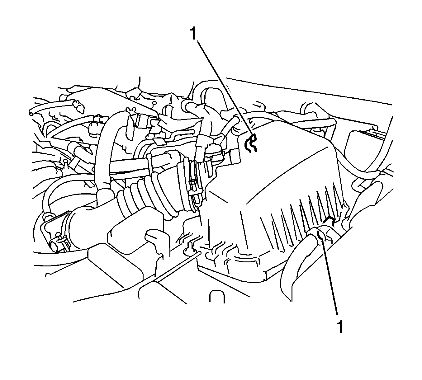
- Unlock the 2 air cleaner case clamps (1).
- Remove the upper portion of the air cleaner case with the hose.
- Cover the air cleaner filter element in order to protect the filter from spills.
- Place a drain pan below the master cylinder.
- Remove the cap from the brake fluid reservoir.
- Remove the filter from the reservoir.
- Siphon the brake fluid from the reservoir.
- If the vehicle has a manual transmission, loosen the clamp and remove the clutch tube (1) from the reservoir.
- Disconnect the connector (1) from the brake fluid level sensor.
- Disengage the clamp from the brake fluid level sensor wire.
- Remove the 2 brake pipes (2) from the master cylinder (4).
- Remove the 2 brake pipes (6) from the 2-way fitting (5).
- Remove the 2 nuts (1) from the 2-way fitting.
- Remove the 2-way fitting from the master cylinder.
- Remove the master cylinder with the reservoir from the vacuum brake booster.
- Remove the seal (3) from the master cylinder.
- Remove the reservoir and the grommets from the master cylinder. Refer to Master Cylinder Reservoir Replacement.


Warning: Refer to Brake Fluid Irritant Warning in the Preface section.
Caution: Refer to Brake Fluid Effects on Paint and Electrical Components Caution in the Preface section.


Note: Hold the master cylinder with the piston facing upward in order to prevent the piston from sliding out.
Inspection Procedure
- Apply chalk to the tip of the accessory tool (1).
- Measure the clearance between the brake booster push rod and the accessory tool.
- If the clearance between the brake booster push rod and the accessory tool is not correct, adjust the length of the brake booster push rod.

Note: The accessory tool comes with a new master cylinder. If you are installing a new master cylinder, inspect the master cylinder piston-to-vacuum brake booster push rod clearance. If you are reusing the original master cylinder, an inspection is not necessary, even with a new brake booster.
If there is a clearance between the accessory tool and the shell of the brake booster, the brake booster push rod is protruding too far.
If the chalk does not stick to the tip of the brake booster push rod, the brake booster push rod is not protruding far enough.
Adjustment Procedure

Hold the brake booster push rod with the J-37767 Adjuster (1) and turn the tip of the rod with a socket driver in order to adjust the length of the rod.
Installation Procedure
- Install the reservoir and the grommets to the master cylinder. Refer to Master Cylinder Reservoir Replacement.
- Bench bleed the master cylinder. Refer to Master Cylinder Bench Bleeding.
- Install the seal (3) to the master cylinder (4).
- Ensure the master cylinder piston is covered with lithium soap base glycol grease, not dirt or any foreign objects.
- Install the master cylinder to the vacuum brake booster.
- Install the 2-way fitting (5) to the master cylinder.
- Install the 2 nuts (1) to the 2-way fitting and tighten to 13 N·m (115 lb in).
- Install the 2 brake pipes (6) to the 2-way fitting. Using a torque wrench with a fulcrum length of 250 mm (9.84 in) and a union nut wrench, tighten the fittings to 14 N·m (124 lb in).
- Install the 2 brake pipes (2) to the master cylinder. Using a torque wrench with a fulcrum length of 250 mm (9.84 in) and a union nut wrench, tighten the fittings to 14 N·m (124 lb in).
- Connect the connector (1) to the brake fluid level sensor.
- Engage the clamp on the brake fluid level sensor wire.
- If the vehicle has a manual transmission, install the clutch tube (1) with the clamp to the reservoir.
- Fill the brake fluid reservoir. Refer to Master Cylinder Reservoir Filling.
- If the vehicle has a manual transmission, bleed the clutch system. Refer to Hydraulic Clutch Bleeding.
- Bleed the entire hydraulic brake system. Refer to Hydraulic Brake System Bleeding.
- Inspect the brake system for leaks. Refer to Brake System External Leak Inspection.
- Remove the cover from the air cleaner filter element.
- Install the upper portion of the air cleaner case with the hose.
- Lock the 2 clamps (1).
- Tighten the hose clamp to 2.0 N·m (18 lb in).
- Install the ventilation hose (1) with the 2 hose clamps.
- Connect the mass air flow meter connector (3).
- Connect the 2 wire harness clamps (1, 2).
- Position the engine cover over the engine.
- Engage the 2 front clips.
- Engage the 2 rear clips.
- Install the left side access panel and engage the 5 claws (1).
- Install the hood rear seal and engage the clip.
- Measure the brake pedal travel. Adjust the brake pedal travel if necessary. Refer to Brake Pedal Travel Measurement and Inspection.

Caution: Refer to Fastener Caution in the Preface section.


Warning: Refer to Brake Fluid Warning in the Preface section.
Caution: Refer to Filling the Master Cylinder Caution in the Preface section.

