Ignition Lock Cylinder Replacement - On Vehicle Without Key
Removal Procedure
- Disconnect the negative battery cable.
- Disable the supplemental inflatable restraint (SIR) system. Refer to Disabling the SIR System in SIR.
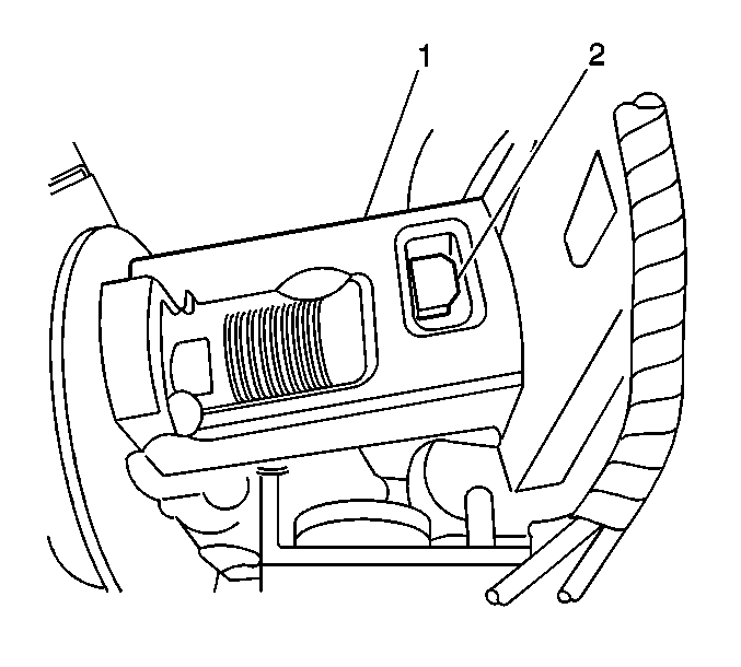
- Remove the steering column trim covers. Refer to Steering Column Trim Covers Replacement - On Vehicle .
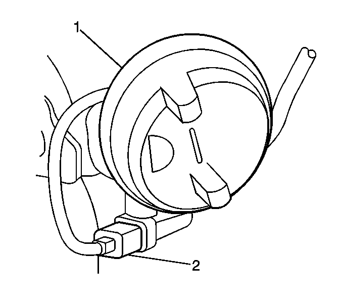
- Drill out the locking button (2) on the rear of the housing assembly (1) using an angle drill.
- Remove the ignition lock cylinder (1) by pulling outward from the steering column.
- Disconnect the electrical connector (2) from the ignition lock cylinder (1).
- Remove the metal shavings from the steering column and ignition lock housing assembly.
Caution: Unless directed otherwise, the ignition and start switch must be in the OFF or LOCK position, and all electrical loads must be OFF before servicing any electrical component. Disconnect the negative battery cable to prevent an electrical spark should a tool or equipment come in contact with an exposed electrical terminal. Failure to follow these precautions may result in personal injury and/or damage to the vehicle or its components.
Caution: This vehicle is equipped with a Supplemental Inflatable Restraint (SIR) System. Failure to follow the correct procedure could cause the following conditions:
• Air bag deployment • Personal injury • Unnecessary SIR system repairs • Refer to SIR Component Views in order to determine if you are performing service on or near the SIR components or the SIR wiring. • If you are performing service on or near the SIR components or the SIR wiring, disable the SIR system. Refer to Disabling the SIR System.
Installation Procedure
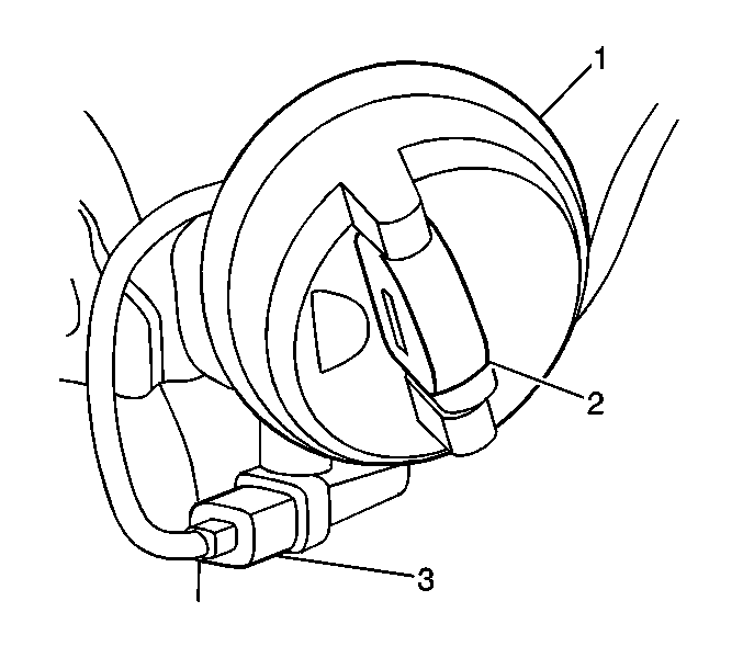
- Connect the electrical connector (3) to the ignition lock cylinder (1).
- Insert the ignition lock cylinder (1) into the housing assembly while rotating the key approximately 5 degrees counter - clockwise.
- Install the steering column trim covers. Refer to Steering Column Trim Covers Replacement - On Vehicle .
- Enable the SIR system. Refer to Enabling the SIR System in SIR.
- Connect the negative battery cable.
- Perform the Passlock Learn Procedure. Refer to Programming Theft Deterrent System Components in Theft Deterrent.
Important: Ensure that all the metal shavings are cleaned from the steering column and ignition housing assembly.
Ignition Lock Cylinder Replacement - On Vehicle With Key
Removal Procedure
- Disconnect the negative battery cable.
- Disable the supplemental inflatable restraint (SIR) system. Refer to Disabling the SIR System in SIR.
- Remove the steering column trim covers. Refer to Steering Column Trim Covers Replacement - On Vehicle .
- Turn the ignition lock cylinder (1) to the RUN position.
- Push the locking button (2) on the rear of the housing assembly (1).
- Remove the ignition lock cylinder by pulling outward from the steering column.
- Disconnect the electrical connector (3) from the ignition lock cylinder (1).
Caution: Unless directed otherwise, the ignition and start switch must be in the OFF or LOCK position, and all electrical loads must be OFF before servicing any electrical component. Disconnect the negative battery cable to prevent an electrical spark should a tool or equipment come in contact with an exposed electrical terminal. Failure to follow these precautions may result in personal injury and/or damage to the vehicle or its components.
Caution: This vehicle is equipped with a Supplemental Inflatable Restraint (SIR) System. Failure to follow the correct procedure could cause the following conditions:
• Air bag deployment • Personal injury • Unnecessary SIR system repairs • Refer to SIR Component Views in order to determine if you are performing service on or near the SIR components or the SIR wiring. • If you are performing service on or near the SIR components or the SIR wiring, disable the SIR system. Refer to Disabling the SIR System.
Installation Procedure
- Connect the electrical connector (3) to the ignition lock cylinder (1).
- Insert the ignition lock cylinder into the housing assembly (1) while rotating the key approximately 5 degrees counter - clockwise.
- Install the steering column trim covers. Refer to Steering Column Trim Covers Replacement - On Vehicle .
- Enable the SIR system. Refer to Enabling the SIR System in SIR.
- Connect the negative battery cable.
- Perform the Passlock Learn Procedure. Refer to Programming Theft Deterrent System Components in Theft Deterrent.
