| Table 1: | Normal Device Power Moding |
| Table 2: | Code Setting Criteria (Fault) for Device Power Moding |
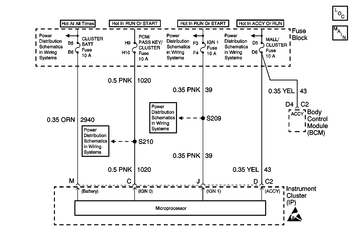
Circuit Description
Class 2 communications will not start until the vehicle systems "on" power mode has been identified. Three discrete wires from the ignition switch contacts are monitored by the Instrument Cluster (IPC) in order to determine the present power mode (ignition switch position). The IPC communicates the system power mode to all class 2 modules on the class 2 serial data line.
Conditions for Running the DTC
The IPC must be powered.
Conditions for Setting the DTC
One of the three monitored ignition switch circuits has malfunctioned.
Action Taken When the DTC Sets
The IPC implements default actions for each ignition switch position when faults are detected.
Conditions for Clearing the DTC
The power moding malfunction must be corrected and then the code can be cleared by using the scan tool. The code also clears after 100 ignition cycles.
Key Position | ACC | IGN 1 | IGN 0 | Engine Running | Power Mode |
|---|---|---|---|---|---|
OFF | Inactive | Inactive | Inactive | No | OFF or RAP |
ACC | Active | Inactive | Inactive | No | ACC |
UNLOCK | Inactive | Inactive | Active | No | UNLOCK or RAP |
CRANK | Inactive | Active | Active | No | CRANK |
RUN | Active | Active | Active | No | RUN |
RUN | Active | Active | Active | Yes | RUN |
ACC | IGN 1 | IGN 0 | Engine Running | Power Mode (Default) |
|---|---|---|---|---|
Inactive | Active | Inactive | No | OFF or RAP |
Inactive | Active | Inactive | Yes | RUN |
Active | Active | Inactive | No | RUN |
Active | Active | Inactive | Yes | RUN |
Inactive | Active | Active | Yes | RUN (Fault is set only if this condition exists for more than 1 minute) |
Active | Inactive | Inactive | Yes | RUN |
Active | Inactive | Active | Yes | RUN |
Step | Action | Value(s) | Yes | No |
|---|---|---|---|---|
1 | Did you perform the instrument cluster diagnostic system check? | -- | Go to Step 2 | |
2 |
Do all of the ignition switch input parameters display on? | -- | Go to Step 6 | Go to Step 3 |
3 | Test the ignition switch circuits that displayed inactive on the scan tool for an open or short to ground. Refer to Circuit Testing and Wiring Repairs in Wiring Systems. Did you find and correct the condition? | -- | Go to Step 12 | Go to Step 4 |
4 | Check for poor connections at the IP. Refer to Testing for Intermittent Conditions and Poor Connections and Connector Repairs in Wiring Systems. Did you find and correct the condition? | -- | Go to Step 12 | Go to Step 5 |
5 | Check for poor connections at the ignition switch. Refer to Testing for Intermittent Conditions and Poor Connections and Connector Repairs in Wiring Systems. Did you find and correct the condition? | -- | Go to Step 12 | Go to Step 11 |
6 |
Does the scan tool communicate and the ignition 1 parameter display active? | -- | Go to Step 8 | Go to Step 7 |
7 |
Is the test lamp off for the ignition switch Ign 1 input and Ign 0 input parameters and on for the ACCY input parameter? | -- | Go to Step 11 | Go to Step 10 |
8 | Test the Ignition switch circuit(s) that displayed Active in Step 6 for a short to voltage. Refer to Circuit Testing and Wiring Repairs in Wiring Systems. Did you find and correct the condition? | -- | Go to Step 12 | Go to Step 9 |
9 |
Did the test lamp illuminate? | -- | Go to Step 10 | Go to Step 11 |
10 | Replace the ignition switch. Refer to Ignition Switch Replacement - On Vehicle in Steering Wheel and Column-Tilt. Did you complete the replacement? | -- | Go to Step 12 | -- |
11 |
Important: Perform the set up procedure for the replacement IP. Replace the IPC. Refer to Instrument Cluster Replacement . Did you complete the replacement and the set up procedure? | -- | Go to Step 12 | -- |
12 | Operate the system in order to verify the repair. Did you find and correct the condition? | -- | System OK | Go to Step 2 |
