For 1990-2009 cars only
Removal Procedure
- Disconnect the battery ground cable. Refer to Battery Negative Cable Disconnection and Connection in Engine Electrical.
- Use a plastic trim tool to remove the ignition switch bezel.
- Remove the instrument panel (I/P) accessory trim plate. Refer to Instrument Panel Accessory Trim Plate Replacement .
- Remove the left I/P insulator. Refer to Instrument Panel Insulator Panel Replacement - Left Side .
- Remove the I/P steering column opening filler panel. Refer to Steering Column Opening Filler Replacement .
- Remove the I/P driver knee bolster. Refer to Driver Knee Bolster Replacement .
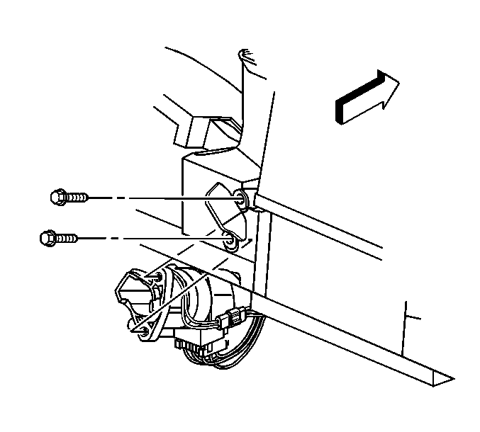
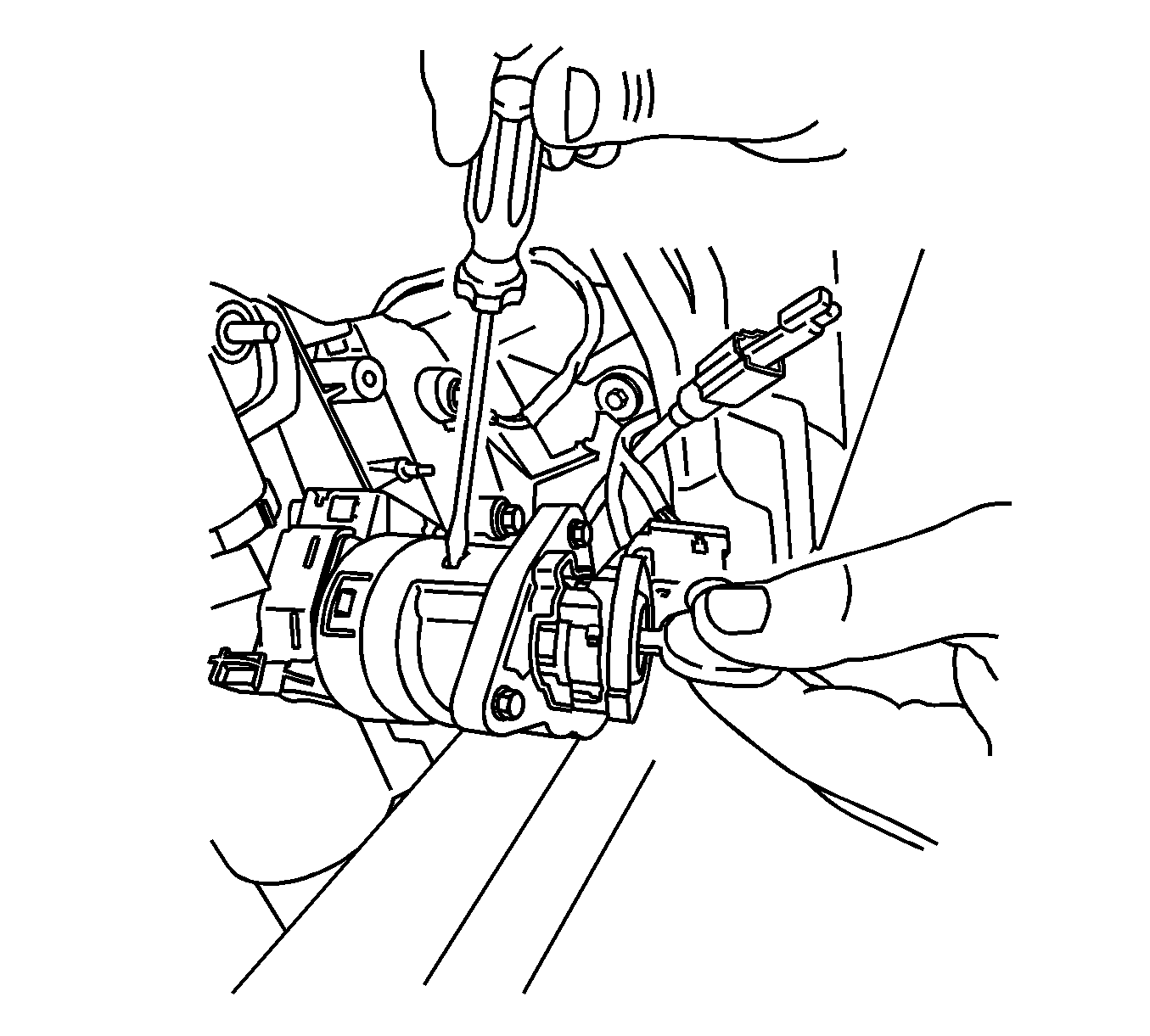
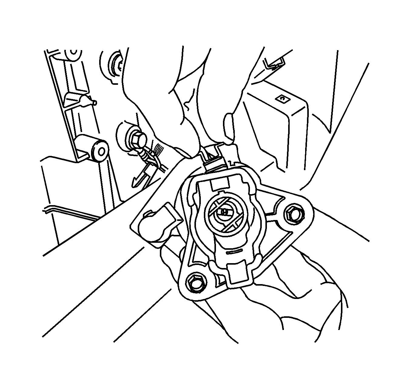
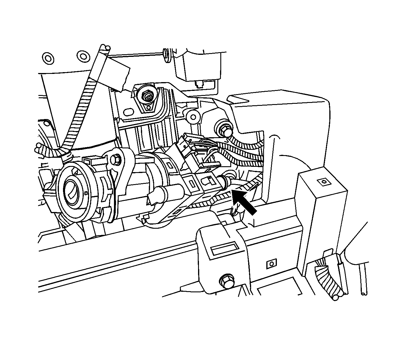
- Remove the ignition switch bolts.
- Lower the ignition switch away from the I/P trim pad.
- Insert the key into the ignition lock cylinder. Turn the key to the ON/RUN position.
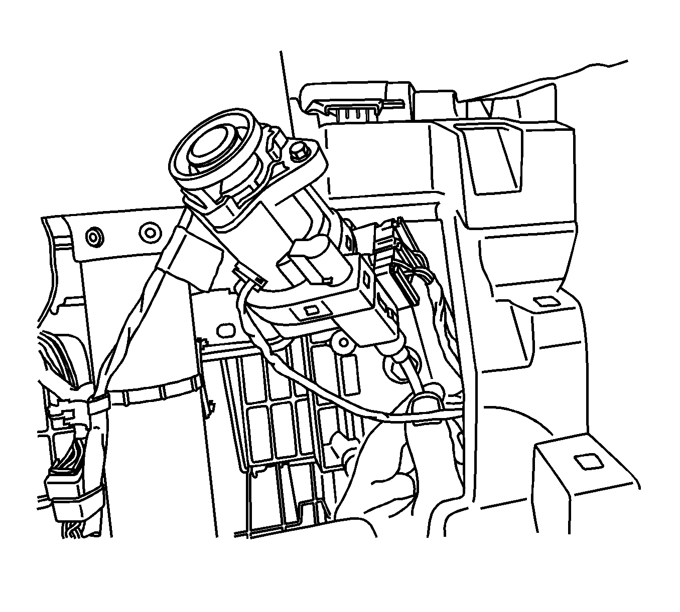
- Depress the retainer to release the transaxle park/lock cable. Pull the park/lock cable from the ignition switch.
- Depress and hold the detent on the bottom of the ignition switch in order to release the ignition lock cylinder. Remove the ignition lock cylinder with the key.
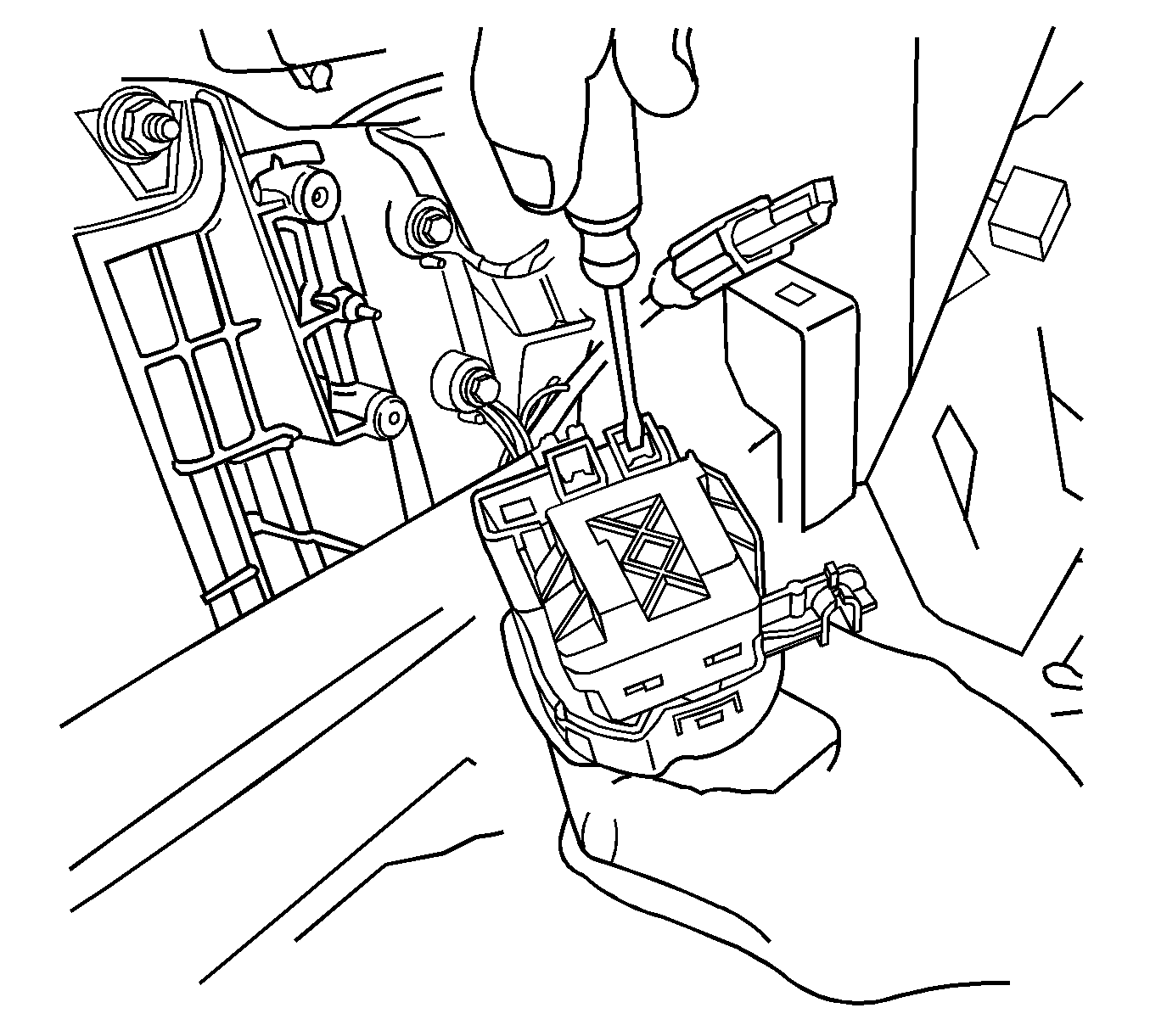
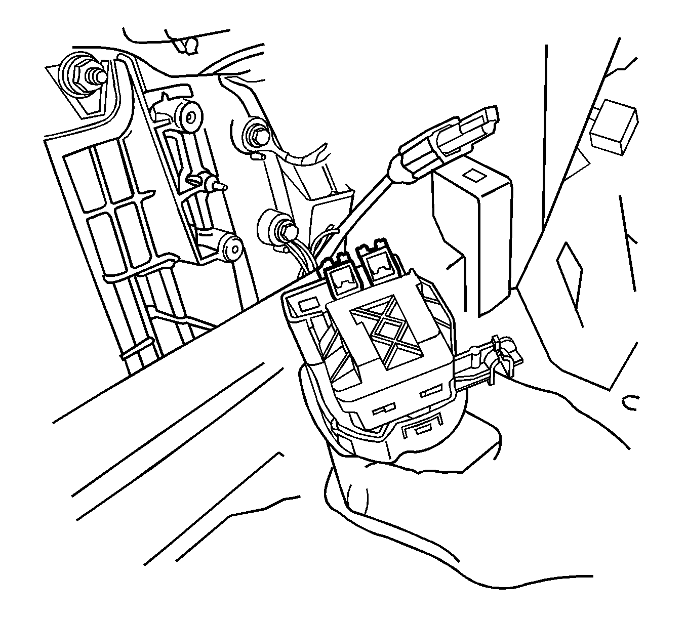
- Disconnect the Passkey™ electrical connector.
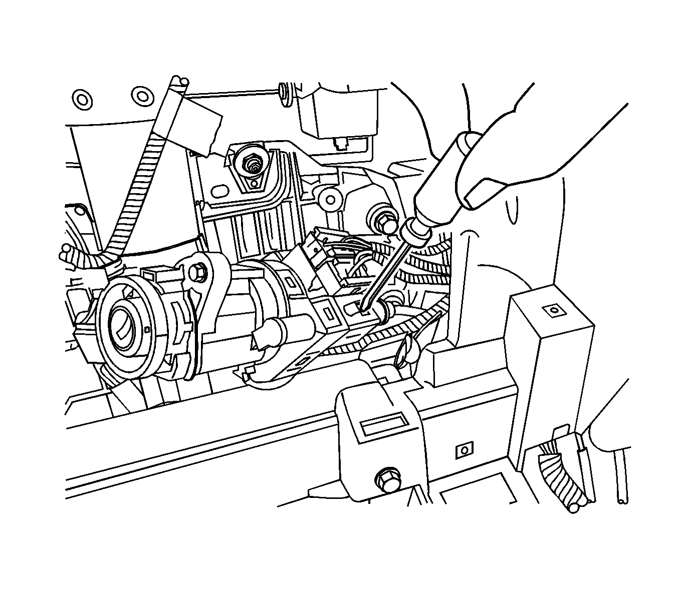
- Disconnect the electrical connectors.
- Remove the I/P ignition and start switch.
- Use the following procedure if the ignition switch lock cylinder is seized or won't rotate:
Important: You cannot remove the Passkey™ electrical connector until the lock cylinder is removed.
| 15.1. | Protect the immediate work area with suitable material such as clean shop towels or a clean fender cover. |
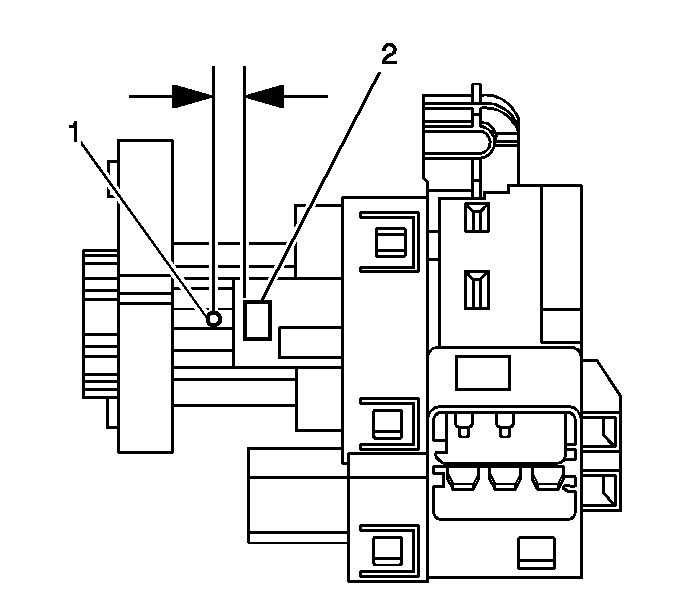
| 15.2. | Locate the surface for the release button (2) for the ignition switch lock cylinder on the plastic ignition switch housing. Center punch a location (1) on the rib approximately 3/8 inch reward, toward the key entry end, from the cylinder release button. |
| 15.3. | Carefully drill a pilot hole through the plastic housing with a 1/8-inch drill bit. |
| 15.4. | Using a 9/32-inch drill bit, carefully drill a larger hole at the pilot location, and slightly into the surface of the ignition switch lock cylinder, to break the release button retaining spring. |
| 15.5. | Remove portions of the broken spring from the hole using a small suitable tool. |
| 15.6. | Grasp the ignition switch lock cylinder and remove the cylinder from the switch housing. |
| 15.7. | Remove any plastic flash from the drilling operation, and using compressed air blow out the ignition switch assembly. |
| 15.8. | Follow service manual procedures when cylinder recoding is required. Refer to Key and Lock Cylinder Coding in General Information. |
Installation Procedure
- Perform the following steps if the ignition switch lock cylinder which you previously removed was seized or would not rotate.
- Connect the electrical connectors.
- Connect the Passkey™ electrical connector.
- Connect the park/lock cable to the ignition switch.
- Turn the key to the ON/RUN position. Install the ignition lock cylinder into the ignition switch.
- Remove the key.
- Position the ignition switch to the I/P trim pad.
- Install the ignition switch bolts.
- Install the I/P driver knee bolster. Refer to Driver Knee Bolster Replacement .
- Install the I/P steering column opening filler panel. Refer to Steering Column Opening Filler Replacement .
- Install the left I/P insulator. Refer to Instrument Panel Insulator Panel Replacement - Left Side .
- Install the I/P accessory trim plate. Refer to Instrument Panel Accessory Trim Plate Replacement .
- Install the ignition switch bezel.
- Connect the battery ground cable. Refer to Battery Negative Cable Disconnection and Connection in Engine Electrical.
| 1.1. | Install the new ignition switch lock cylinder as required by rotating both the cylinder and the ignition switch to the ON position. |
| 1.2. | Push the ignition switch lock cylinder into the ignition switch housing until fully seated. |
| 1.3. | You may have to slightly depress the release button as the button passes by the 9/32-in hole previously drilled in the ignition switch housing. |
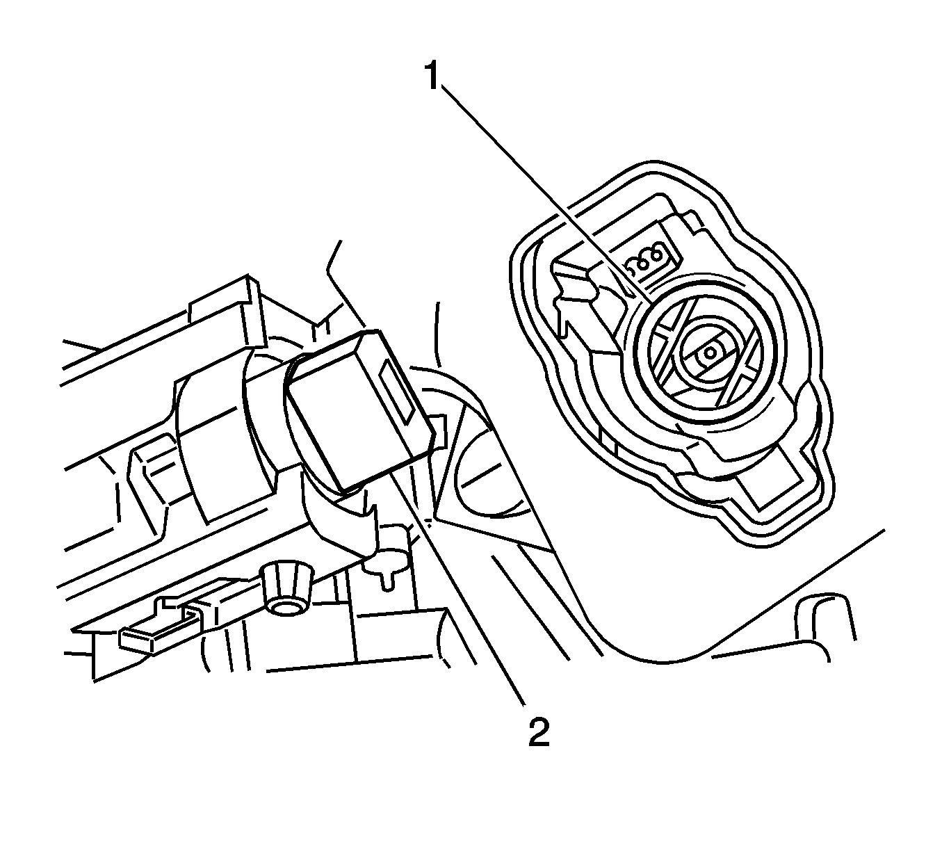
If you turned the key slightly while removing the lock cylinder, you may have to align the white colored ignition switch rotor (1) with the lock cylinder (2). You can rotate the switch rotor with your finger.
Notice: Refer to Fastener Notice in the Preface section.
Tighten
Tighten the bolts to 10 N·m (89 lb in).
