For 1990-2009 cars only
Removal Procedure
- Remove the knee bolster. Refer to Knee Bolster Replacement .
- Remove the closeout panel. Refer to Instrument Panel Insulator Panel Replacement - Left Side .
- Remove the electrical connector from the brake apply sensor.
- Remove the steering column assembly from the vehicle. Refer to Steering Column Replacement .
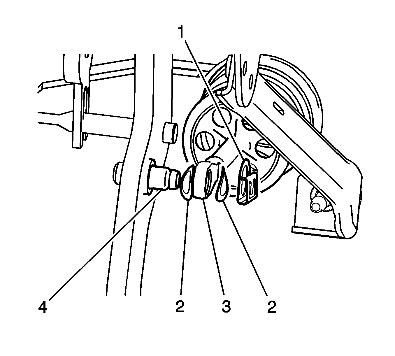
- Disconnect the brake pedal pushrod retaining clip (1) the wave washers (2) and the brake booster pushrod (3) from the brake pedal pin (4).
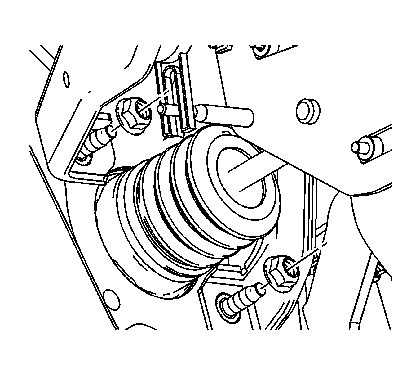
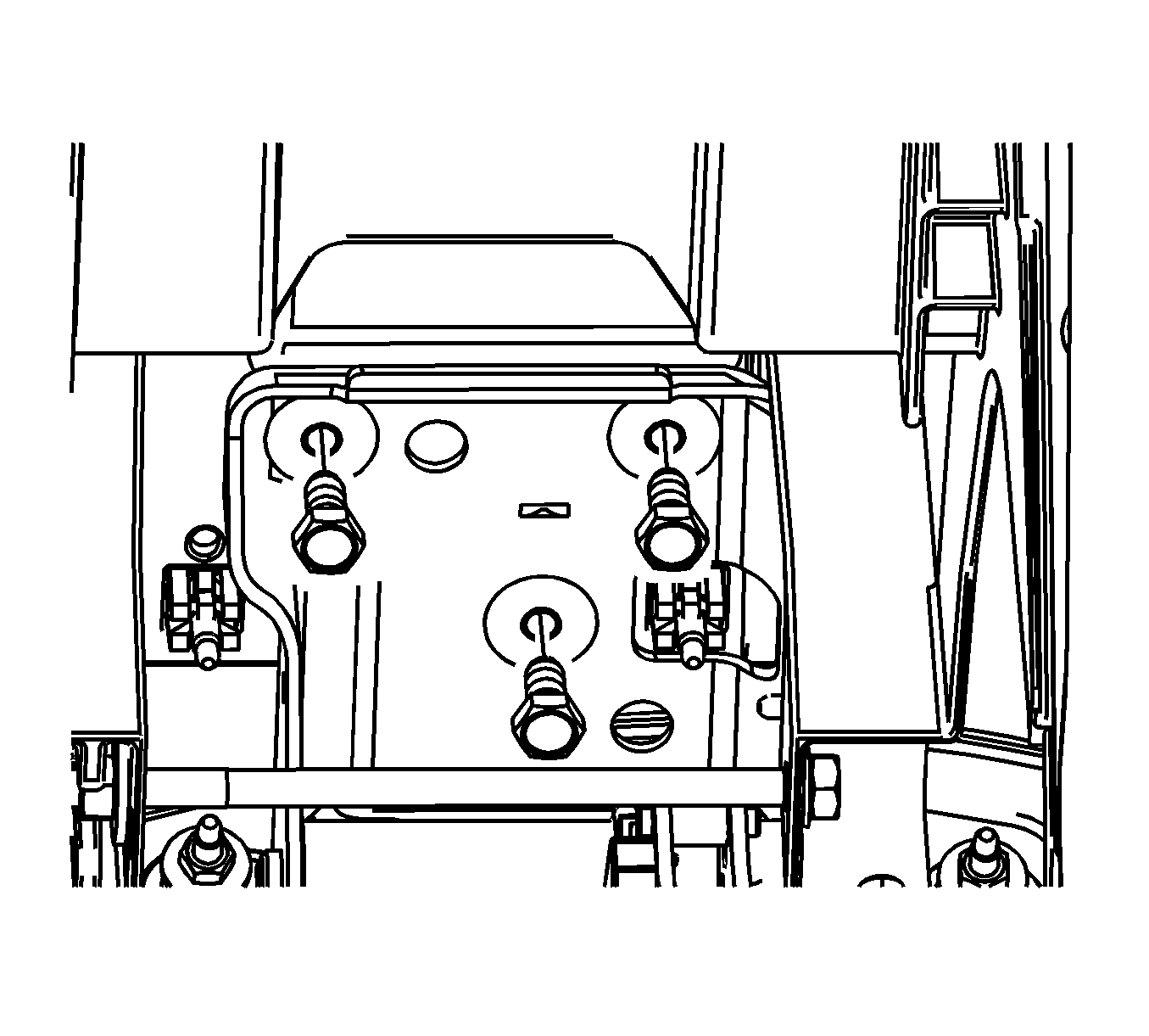
- Remove the 2 brake pedal assembly to cowl mounting nuts.
- Remove the 3 brake pedal assembly to instrument panel (I/P) carrier bolts.
- Remove the brake pedal assembly from the vehicle.
Installation Procedure
- Install the brake pedal assembly to the vehicle.
- Install the 3 brake pedal assembly to I/P carrier bolts.
- Install the 2 brake pedal assembly to cowl mounting nuts.
- Connect the brake pedal pushrod retaining clip (1) the wave washers (2) and the brake booster pushrod (3) to the brake pedal pin (4).
- Install the steering column assembly to the vehicle. Refer to Steering Column Replacement .
- Install the electrical connector to the brake apply sensor.
- Install the closeout panel. Refer to Instrument Panel Insulator Panel Replacement - Left Side .
- Install the knee bolster. Refer to Knee Bolster Replacement .
- Calibrate the brake pedal position sensor. Refer to Brake Pedal Position Sensor Calibration .
Notice: Refer to Fastener Notice in the Preface section.
Tighten
Tighten the bolts to 25 N·m (18 lb ft).
Tighten
Tighten the nuts to 15 N·m (11 lb ft).
