For 1990-2009 cars only
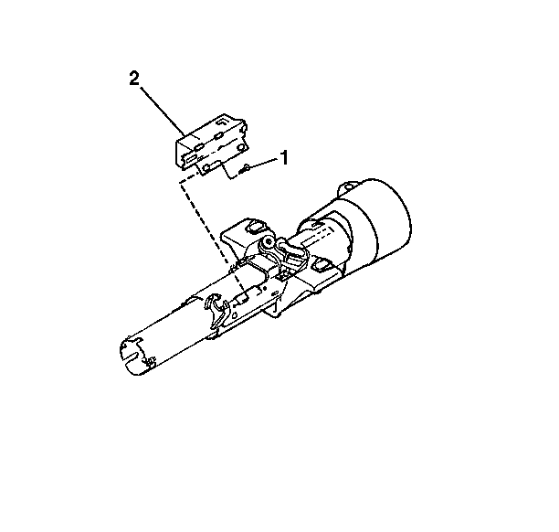
- Install the vehicle wire harness into the ignition switch assembly (2).
- Install the ignition switch assembly (2) to the ignition switch actuator assembly.
- Install the flat head screw (1) to the ignition switch assembly (2).
- Tighten the flat head screw (1) finger tight.
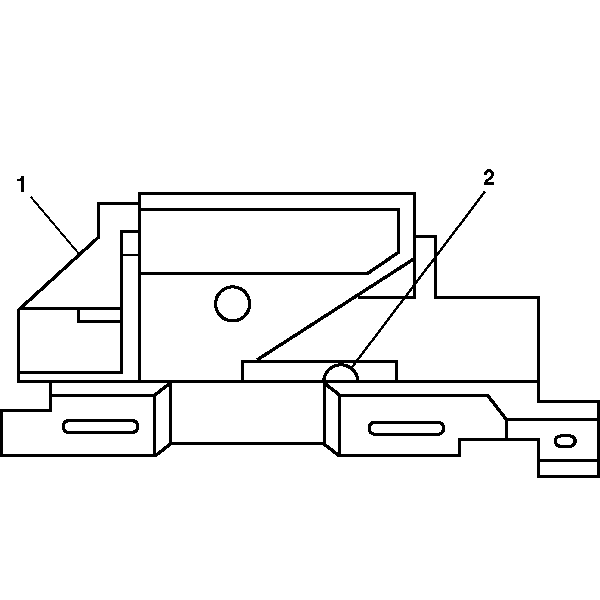
- Move the ignition switch assembly slider (2) to the far right position.
- Move the ignition switch assembly slider (2) to the left. This is the OFF-LOCK position.
- Install a 3/32 inch drill bit into the hole on the ignition switch assembly (1) to limit travel.
- Push against the ignition switch actuator assembly to limit all the lash.
- Install the flat head screw.
- Install the dimmer switch assembly. Refer to Dimmer Switch Assembly - Assemble - Off Vehicle .
- Enable the inflatable restraint steering wheel module. Refer to Enabling the SIR System in SIR.
Notice: Use the correct fastener in the correct location. Replacement fasteners must be the correct part number for that application. Fasteners requiring replacement or fasteners requiring the use of thread locking compound or sealant are identified in the service procedure. Do not use paints, lubricants, or corrosion inhibitors on fasteners or fastener joint surfaces unless specified. These coatings affect fastener torque and joint clamping force and may damage the fastener. Use the correct tightening sequence and specifications when installing fasteners in order to avoid damage to parts and systems.
Tighten
Tighten the screw to 4 N·m (35 lb in).
