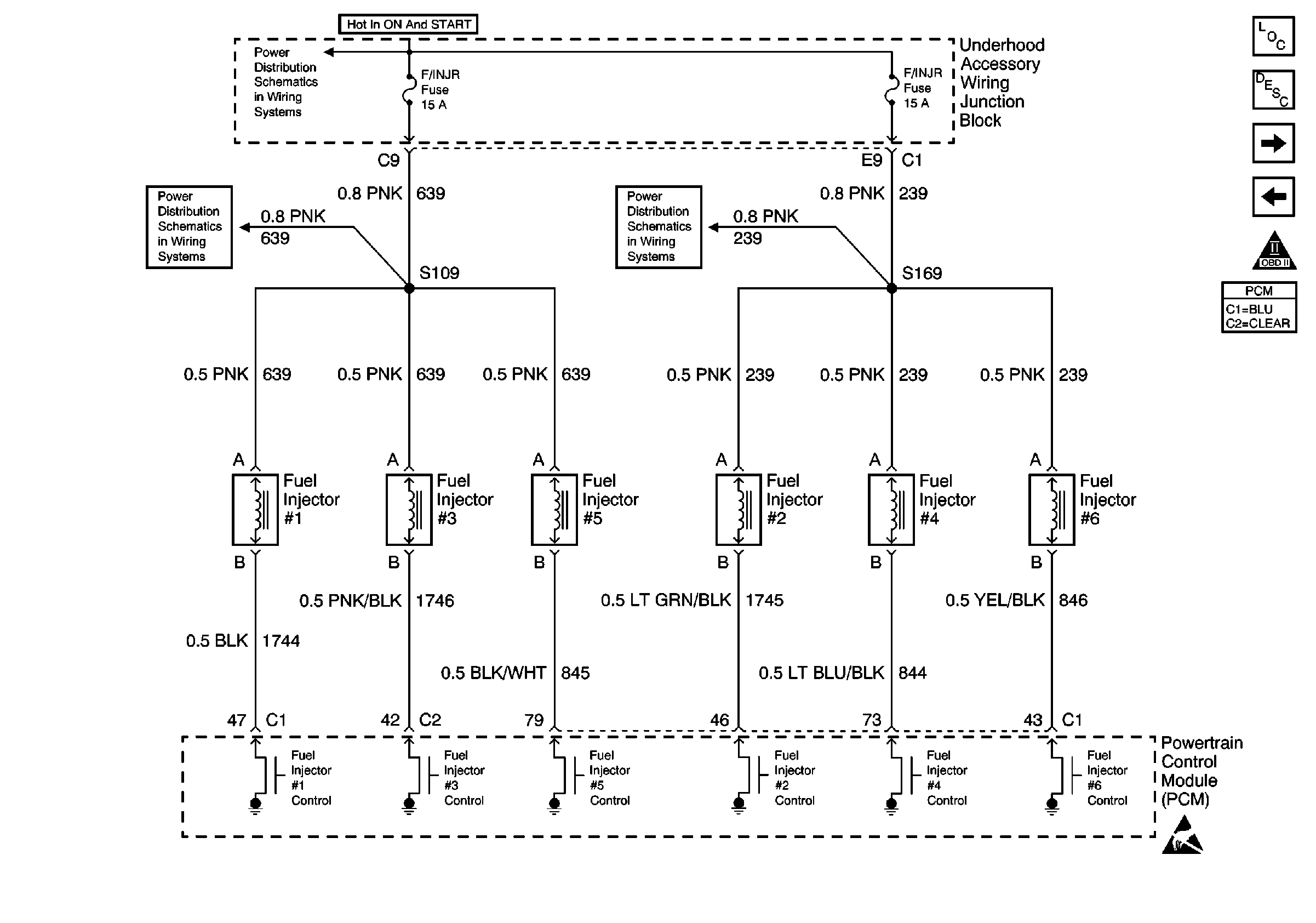
Refer to Engine Controls Schematics
Fuel Injectors
.
Circuit Description
Ignition voltage is supplied directly to the fuel injectors. The powertrain control module (PCM) controls each fuel injector by grounding the control circuit via an internal solid state device called a driver. The primary function of the driver is to supply the ground for the component being controlled. Each driver has a fault line which is monitored by the PCM. When the PCM is commanding a component on, the voltage of the control circuit should be low (near 0 volts). When the PCM is commanding the control circuit to a component off, the voltage potential of the circuit should be high (near battery voltage). If the fault detection circuit senses a voltage other than what is expected, this DTC will set.
The PCM will monitor the control circuit for the following:
| • | A short to ground |
| • | A short to voltage |
| • | An open circuit |
| • | An open injector coil |
| • | An internally shorted or excessively low resistance fuel injector |
When the PCM detects any of the above malfunctions, this DTC will set and the affected driver will be disabled. The PCM will continue to test the circuit and if the fault goes away, the driver will be reactivated.
Conditions for Running the DTC
| • | Engine running |
| • | Ignition voltage is between 9.0 volts and 17.0 volts. |
Conditions for Setting the DTC
The PCM detects an incorrect voltage potential on the ignition control circuit.
Action Taken When the DTC Sets
| • | The PCM illuminates the malfunction indicator lamp (MIL) on the second consecutive ignition cycle that the diagnostic runs and fails. |
| • | The PCM records the operating conditions at the time the diagnostic fails. The first time the diagnostic fails, the PCM stores this information in the Failure Records. If the diagnostic reports a failure on the second consecutive ignition cycle, the PCM records the operating conditions at the time of the failure. The PCM writes the conditions to the Freeze Frame and updates the Failure Records. |
Conditions for Clearing the MIL/DTC
| • | The PCM turns the MIL OFF after 3 consecutive drive trips during which the diagnostic runs and passes. |
| • | A last test failed, or the current DTC, clears when the diagnostic runs and passes. |
| • | A History DTC clears after 40 consecutive warm-up cycles, if no other emission related diagnostic failures are reported. |
| • | Use a scan tool in order to clear the MIL diagnostic trouble code. |
| • | Interrupting the PCM battery voltage may or may not clear DTCs. This practice is not recommended. Refer to Powertrain Control Module Description , Clearing Diagnostic Trouble Codes. |
Diagnostic Aids
Notice: Use the connector test adapter kit J 35616-A for any test that
requires probing the following items:
• The PCM harness connectors • The electrical center fuse/relay cavities • The component terminals • The component harness connector
If the problem is intermittent, refer to Intermittent Conditions .
Test Description
The numbers below refer to the step numbers on the diagnostic table.
-
The scan tool displays Fault if a circuit problem is detected.
-
Refer to the system mechanization for the fuses that supply these circuits.
Step | Action | Values | Yes | No |
|---|---|---|---|---|
1 | Did you perform the Powertrain On-Board Diagnostic (OBD) System Check? | -- | ||
Does the scan tool continuously indicate OK? | -- | Go to Diagnostic Aids. | ||
3 | Is an entire bank of cylinders inoperative? | -- | ||
Are the fuel injector fuses OK? | -- | |||
5 |
Is battery voltage indicated? | -- | ||
6 |
Does the test lamp flash on and off as the engine cranks for all injectors tested? | -- | ||
7 |
Does the DMM display either the value shown or a lesser value? | 5 ohms | ||
8 | Using a DMM J 39200 check for continuity between the injector control circuit and a ground. The DMM should display infinite resistance. Does the DMM display infinite resistance? | ∞ | ||
9 |
Is a short to voltage indicated? | -- | ||
10 |
The DMM should display infinite resistance. Does the DMM display infinite resistance? | ∞ | ||
11 |
Was a problem found and corrected? | -- | ||
12 | Repair open or high resistance in the ignition feed circuit. Refer to Wiring Repairs in Wiring Systems. Is the action complete? | -- | -- | |
13 | Repair the open or high resistance in the injector control circuit. Refer to Wiring Repairs in Wiring Systems. Is the action complete? | -- | -- | |
14 | Repair the short to ground in the injector control circuit. Refer to Wiring Repairs in Wiring Systems. Is the action complete? | -- | -- | |
15 | Repair the short to power in the injector control circuit. Refer to Wiring Repairs in Wiring Systems. Is the action complete? | -- | -- | |
16 | Repair the injector control circuits that are shorted together. Refer to Wiring Repairs in Wiring Systems. Is the action complete? | -- | -- | |
17 | Perform the fuel injector coil test. Refer to Fuel Injector Solenoid Coil Test - Engine Coolant Temperature Between 10-35 Degrees C (50-95 Degrees F) or Fuel Injector Solenoid Coil Test - Engine Coolant Temperature Outside 10-35 Degrees C (50-95 Degrees F) . Is the action complete? | -- | -- | |
18 | Check for faulty connections or faulty terminal tension at the fuel injector. Refer to Testing for Intermittent Conditions and Poor Connections in Wiring Systems. . Was a problem found and corrected? | -- | ||
19 | Replace the fuel injector. Refer to Fuel Injector Replacement . Is the action complete? | -- | -- | |
20 | Check for poor connections or faulty terminal tension at the PCM harness connector. Refer to Testing for Intermittent Conditions and Poor Connections in Wiring Systems. . Was a problem found and corrected. | -- | ||
21 |
Important: The replacement PCM must be programmed. Replace the PCM. Refer to Powertrain Control Module Replacement/Programming . Is the action complete? | -- | -- | |
22 |
Does the scan tool indicate that this test ran and passed? | -- | ||
23 | Review the Captured Info using the scan tool. Are there any DTCs that have not been diagnosed? | -- | Go to the applicable DTC table | System OK |
