Service of the powertrain control module (PCM) should normally consist of either
replacement of the PCM or EEPROM programming. If the diagnostic procedures call for
PCM replacement, check the PCM first to see if the PCM is the correct part.
If the PCM is faulty, remove the PCM and install the new service PCM.
The new service PCM will not be programmed. You must program the new PCM. DTC
P0602 indicates the EEPROM is not programmed or has malfunctioned.
Notice: Do not touch the connector pins or soldered components on the circuit
board in order to prevent possible electrostatic discharge (ESD) damage to
the PCM.
There are no user serviceable parts in this PCM. The PCM should never be opened
for any reason.
Notice: Turn the ignition OFF when installing or removing the PCM connectors
and disconnecting or reconnecting the power to the PCM (battery cable, PCM
pigtail, PCM fuse, jumper cables, etc.) in order to prevent internal PCM damage.
Important: When replacing the production PCM with a
service PCM, it is important to transfer the broadcast code and production PCM number
to the service PCM label. Do not record the information on the PCM cover.
This will allow positive identification of the PCM parts throughout the
service life of the vehicle.
Removal Procedure
Important: It is necessary to record the remaining engine
oil life. If the replacement module is not programed with the remaining engine oil
life, the engine oil life will default to 100%. If the replacement module is not programmed
with the remaining engine oil life, the engine oil will need to be changed at 5000 km
(3,000 mi) from the last engine oil change.
- Using a scan tool, retrieve the percentage of remaining engine oil. Record the
remaining engine oil life.
Caution: Unless directed otherwise, the ignition and start switch must be in the OFF or LOCK position, and all electrical loads must be OFF before servicing
any electrical component. Disconnect the negative battery cable to prevent an electrical spark should a tool or equipment come in contact with an exposed electrical terminal. Failure to follow these precautions may result in personal injury and/or damage to
the vehicle or its components.
- Disconnect the negative battery cable.
- Remove the left strut brace.
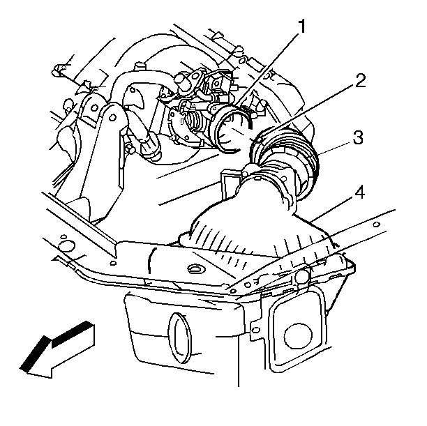
- Loosen the band clamp (2) at the throttle body (1), and
disconnect the air duct (3) from the throttle body.
- Disconnect the electrical connectors for the intake air temperature (IAT)
sensor and the mass air flow (MAF) sensor .
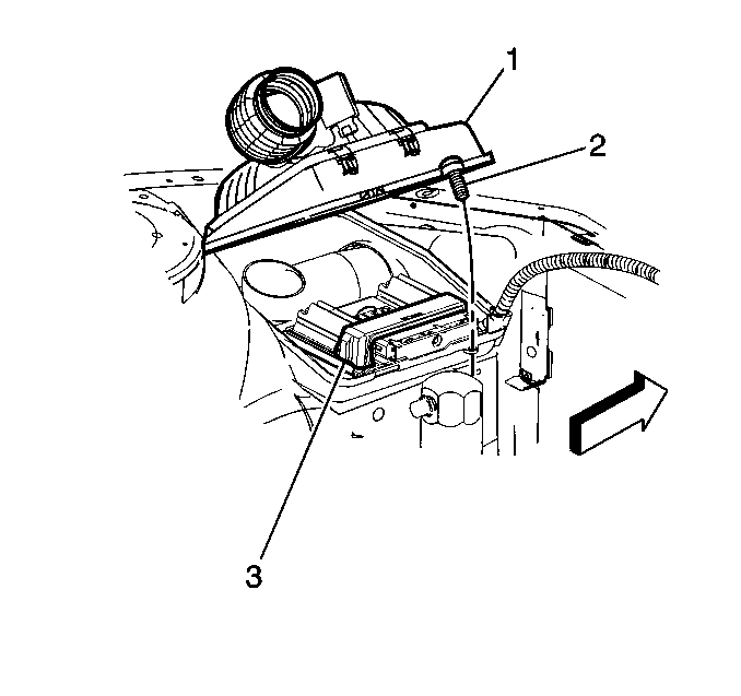
- Loosen the retaining screw (2) for the air cleaner cover .
- Remove the air cleaner cover (1) and lift the PCM (3) from
the housing assembly.
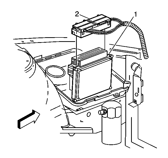
- Disconnect
the harness connectors (2) from the PCM (1).
- Remove the PCM from the engine compartment.
Installation Procedure
- Install
the connectors (2) to the PCM (1).
- Install the PCM (3) into the air cleaner housing assembly.
- Install the air cleaner housing cover (1).
- Tighten the retaining screw (2) for the air cleaner cover .
- Reconnect the air duct (3) to the
throttle body (1), and tighten the band clamp (2) at the throttle body
.
- Reconnect the electrical connectors for the IAT sensor and the MAF sensor
.
- Install the strut brace.
- Connect the negative battery cable.
- If a new PCM is being installed, program the EEPROM.
Before Programming a Control Module
Important: Do NOT program a control module unless you
are directed by a service procedure or you are directed by a General Motors Corporation
service bulletin. Programming a control module at any other time will not permanently
correct a customers concern.
Ensure the following conditions are met before programming a control module:
| - | There is no charging system concern. All charging system concerns must
be repaired before programming a control module. |
| - | Battery voltage is greater than 12 volts but less than 16 volts.
The battery must be charged before programming the control module if the battery
voltage is low. |
| - | A battery charger is NOT connected to the vehicle's battery. Incorrect
system voltage or voltage fluctuations from a battery charger, may cause programming
failure or control module damage. |
| - | Turn OFF or disable any system that may put a load on the vehicle's battery. |
| • | Daytime running lights (DRL). Applying the parking brake, on most vehicles,
disables the DRL system. Refer to the Owners manual. |
| • | Engine cooling fans etc. |
| • | The ignition switch is in the proper position. The scan tool prompts you
to turn ON the ignition, with the engine OFF. Do NOT change the position of the
ignition switch during the programming procedure, unless instructed to do so. |
| • | All tool connections are secure. |
| - | The connection at the DLC is secure. |
| - | Voltage supply circuits |
| • | DO NOT disturb the tool harnesses while programming. If an interruption
occurs during the programming procedure, programming failure or control module damage
may occur. |
Important: The following procedure must be performed
in order to prevent the odometer from incrementing up to 16 miles when the PCM is
re-flashed.
- Park the vehicle.
- Connect the Tech 2.
- Build the vehicle within the powertrain area of the Tech 2.
- Select Special Functions.
- Select Output Controls.
- Scroll to Oil Life Reset.
- On the Tech 2 screen, the actual oil life remaining is in the
upper right corner. Select up or down 2% of the oil life, I.E. 18 percent left, enter
16 percent or 20 percent with the numeric key pad and then select Perform Reset.
- With the ignition key on, read the amount of engine oil life remaining
with the Tech 2.
- Turn the ignition key off for ten seconds.
- Turn the ignition key on and re-flash the PCM per the re-flash procedure.
Remote Programming
- Turn OFF the ignition.
- Install the Tech 2™ to the data link connector (DLC).
- Turn ON the ignition, with the engine OFF.
- Turn OFF all vehicle accessories.
- With the Tech 2™, select Service Programming.
- Identify vehicle information as requested by the Tech 2™.
- Select the type of module you are programming.
- Select the type of programming to be performed.
- Verify the displayed VIN with the vehicle VIN. If the displayed VIN does
not match the actual VIN, write down the actual VIN and correct the VIN at the Techline™
terminal.
- When complete, Exit Service Programming.
- Turn OFF the Tech 2™ and disconnect the Tech 2™
from the vehicle.
- Turn OFF the ignition.
- Connect the Tech 2™ to the Techline™ terminal.
- Select Service Programming.
- Select Tech 2™ as the tool you are using.
- Select the type of programming to be performed.
- Verify the displayed VIN with the vehicle VIN. Correct the VIN as necessary.
- Select the type of module you are programming.
- Identify what type of programming that you are performing.
| • | Normal--This type of programming is for updating an existing calibration
or programming a new controller. |
| • | Vehicle Configuration Index (VCI)--This selection is used if the
vehicle VIN is unavailable or not recognized by the Techline™ terminal. Observe,
you will need to contact the Techline™ Customer Support center to use this
option. |
| • | Reconfigure--This is to reconfigure a vehicle, such as tire size
and axle ratio changes. |
- Select the appropriate calibration file.
- Ensure all connections are secure.
- Select Reprog to initiate the download of the new calibration to the Tech 2™.
- After the download is complete, turn OFF the Tech 2™.
- Disconnect the Tech 2™ from the Techline™ terminal.
- Install the Tech 2™ to the data link connector (DLC).
- Turn ON the Tech 2™.
- Turn ON the ignition, with the engine OFF.
- Select Service Programming.
Important: DO NOT turn OFF the ignition if the programming
procedure is interrupted or unsuccessful. Ensure that all the PCM and DLC connections
are secure and the Techline™ operating software is up to date. Attempt to
reprogram the control module. If the control module cannot be programmed, replace
the control module. Refer to Removal and Installation procedures in this section.
- Select Program.
- After the download is complete, EXIT Service Programming.
- Turn OFF the ignition for 30 seconds.
- Turn OFF the Tech 2™.
- If a control module is replaced the following service procedures must
be performed:
| • | Programming Theft Deterrent System Components |
Programming Verification
- With a scan tool, clear the DTCs.
- Attempt to start the engine.
- Repeat the Service Programming procedure if the engine does not start
or operates poorly. Perform the following procedures before programming the PCM:
| • | Ensure the control module and DLC connections are OK. |
| • | Ensure the Techline™ operating software is up to date. |
| • | Ensure the calibration part number is correct for the vehicle. |
- Attempt to program the control module. If the control module still cannot
be programmed properly, replace the control module. Refer to Removal and Installation
procedures in this section. You must program the replacement control module.
Before Programming a Control Module
Important:
| • | Do NOT program a control module unless you are directed by a service
procedure or you are directed by a General Motors Corporation service bulletin.
Programming a control module at any other time will not permanently correct a customer's
concern. |
| • | The Off-Board Programming is used in situations where a control module
must be programmed without having the vehicle present. The Off-Board Programming
Adapter must be used to perform the Off-Board Programming procedure. The adapter
allows the control module to power up and allows the Tech 2™ to communicate
with the control module. |
| • | DO NOT disturb the tool harnesses while programming. If an interruption
occurs during the programming procedure, programming failure or control module damage
may occur. |
Ensure that all connections are secure at the following locations:
| • | The Off-Board Programming Adapter |
Important: The following procedure must be performed
in order to prevent the odometer from incrementing up to 16 miles when the PCM is
re-flashed.
- Park the vehicle.
- Connect the Tech 2.
- Build the vehicle within the powertrain area of the Tech 2.
- Select Special Functions.
- Select Output Controls.
- Scroll to Oil Life Reset.
- On the Tech 2 screen, the actual oil life remaining is in the
upper right corner. Select up or down 2% of the oil life, I.E. 18 percent left, enter
16 percent or 20 percent with the numeric key pad and then select Perform Reset.
- With the ignition key on, read the amount of engine oil life remaining
with the Tech 2.
- Turn the ignition key off for ten seconds.
- Turn the ignition key on and re-flash the PCM per the re-flash procedure.
Off-Board Programming
- Obtain the VIN of the vehicle for which the control module is being programmed.
- With the Techline™ terminal, select Service Programming.
- Select Tech 2™, Reprogram ECU, and Off-Board Programming
Adapter as the ECU location.
- Connect the control module, Off-Board Programming Adapter, and the Tech 2™
as described on the Techline™ terminal. Ensure you use the correct harness
connector from the Off-Board Programming Adapter kit.
- With the Tech 2™, select Service Programming Request Information
function. The Tech 2™ communicates with the control module and receives
the access code.
- With the Tech 2™, exit the Service Programming Request Information.
- Disconnect the Tech 2™ from the Off-Board Programming Adapter.
- Connect the Tech 2™ to the Techline™ terminal.
- Turn ON the Tech 2™.
- With the Techline™ terminal, enter the VIN of the vehicle that will
be receiving the control module.
- The Techline™ terminal will display the message, attaching to database.
- Identify what type of programming that you are performing.
- Select the appropriate calibration file.
- Ensure all connections are secure.
- The Techline™ terminal displays a summary screen that summarizes
your selections. After confirming you choices, the Techline™ terminal automatically
loads the calibration files to the Tech 2™.
- After the download is complete, turn OFF the Tech 2™.
- Disconnect the Tech 2™ from the Techline™ terminal.
- Connect the Tech 2™ to the Off-Board Programming Adapter.
- With the Tech 2™, select Service Programming.
Important: DO NOT turn OFF the Off-Board Programming
Adapter if the programming procedure is interrupted or unsuccessful. Ensure the control
module and the Off-Board Programming Adapter connections are secure and the Techline™
operating software is up to date. Attempt to reprogram the control module. If
the control module cannot be programmed, replace the control module.
- With the Tech 2™, select Program.
- After the download is complete, exit Service Programming.
- Turn OFF the Off-Board Programming Adapter.
