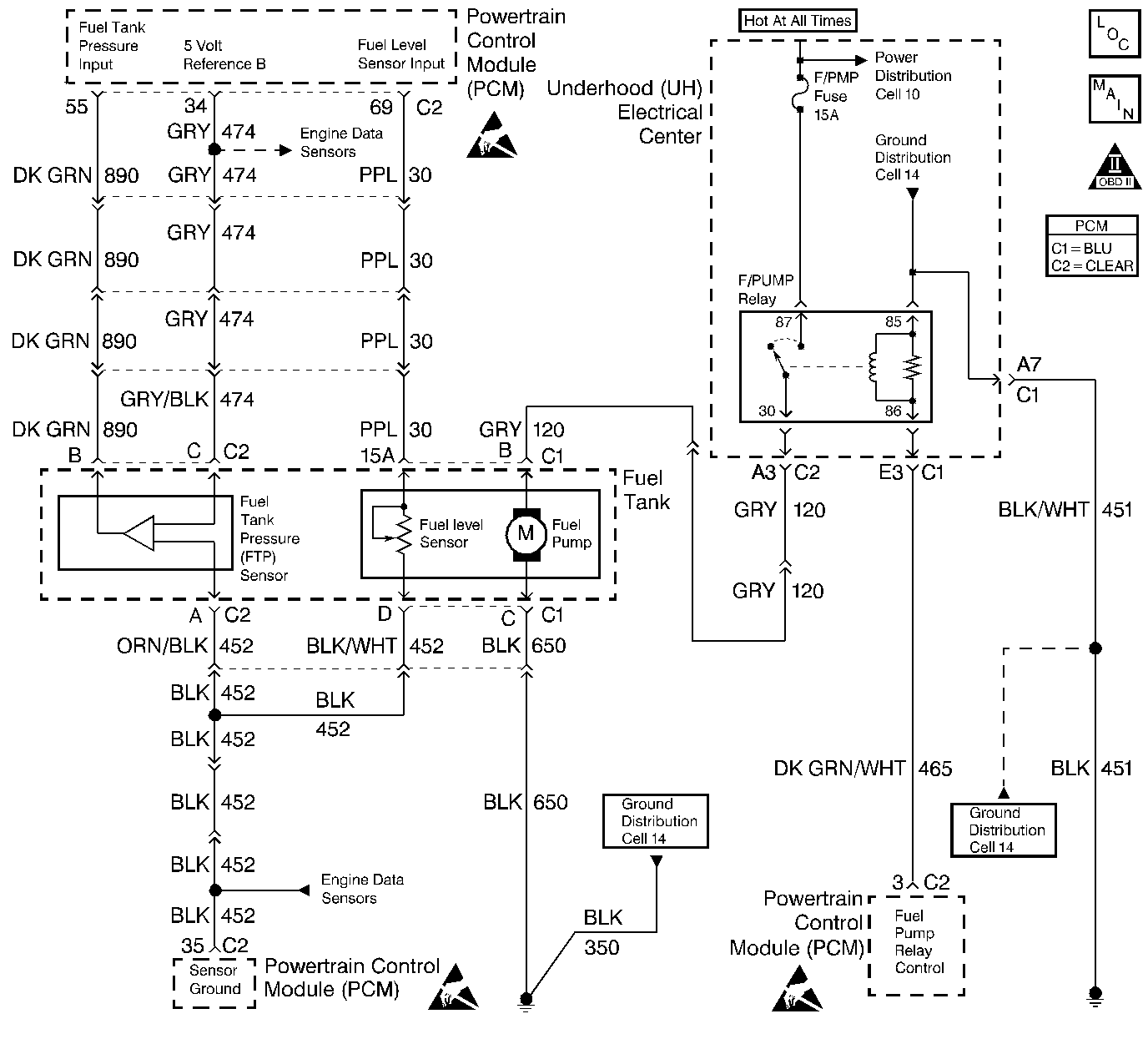
Circuit Description
The fuel pump relay supplies power to the fuel pump. When the ignition switch is first turned on, the powertrain control module (PCM) energizes the fuel pump relay for approximately 2 seconds. This allows the fuel pump to prime the fuel rail assembly. The fuel pump relay remains on as long as the PCM receives reference pulses from the ignition control module (ICM). If the PCM does not receive the reference pulses, the PCM de-energizes the fuel pump relay.
Diagnostic Aids
With the engine stopped, the fuel pump may be turned on using the scan tool output controls function.
An intermittent may be caused by a faulty connection, rubbed through the wire insulation, or a wire broken inside of the insulation.
Inspect for a faulty connection or a damaged harness. Inspect the PCM harness and connectors for the following conditions:
| • | Improper mating |
| • | Broken locks |
| • | Improperly formed or damaged terminals |
| • | Faulty terminal to wire connections |
| • | Any damaged harnesses |
Test Description
The number below refers to the step number on the diagnostic table:
Step | Action | Value(s) | Yes | No |
|---|---|---|---|---|
1 | Did you perform the Powertrain On-Board Diagnostic System Check? | -- | ||
Is DTC P0230 - Fuel Pump Control Circuit set? | -- | |||
3 |
Does the test lamp illuminate? | -- | ||
4 | Inspect for a blown fuel pump fuse. Is the fuel pump fuse blown? | -- | ||
5 |
Does the test lamp illuminate? | -- | ||
6 |
Does the test lamp illuminate? | -- | ||
7 |
Is the fuel pressure within the specified range? | 333-376 kPa (48-55 psi) | ||
8 |
Does the test lamp illuminate? | -- | ||
9 | Connect the test lamp between the fuel pump feed terminal and ground. Does the test lamp illuminate? | -- | ||
10 | Locate and repair the open in the fuel pump feed relay circuit. Refer to Wiring Repairs in Wiring Systems. Did you complete the repair? | -- | -- | |
11 | Locate and repair the short to ground in the fuel pump relay feed circuit. Refer to Wiring Repairs in Wiring Systems. Did you complete the repair? | -- | -- | |
12 | Locate and repair the short to ground in the fuel pump feed (CKT 120). Refer to Wiring Repairs in Wiring Systems. Did you complete the repair? | -- | -- | |
13 |
Did you complete the repair? | -- | ||
14 |
Did you complete the repair? | -- | ||
15 | Locate and repair the open in the fuel pump ground circuit (CKT 350). Refer to Wiring Repairs in Wiring Systems. Did you complete the repair? | -- | -- | |
16 | Locate and repair the open in the fuel pump feed circuit (CKT 120). Refer to Wiring Repairs in Wiring Systems. Did you complete the repair? | -- | -- | |
17 | Replace the fuel pump. Refer to Fuel Sender Assembly Replacement . Is action complete? | -- | -- | |
18 | Replace the fuel pump relay. Refer to Fuel Pump Relay Replacement . Did you complete the repair? | -- | -- | |
19 |
Is the fuel pressure within the specified range? | 333-376 kPa (48-55 psi) | System OK |
