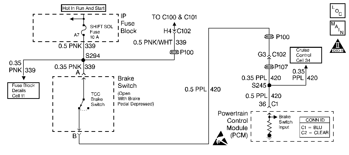
Circuit Description
The torque converter clutch (TCC) brake switch is used to indicate the status of the brake pedal (applied or released).
When the PCM detects a status change on the brake lamp switch, and the extended travel brake switch input, without a transition on the TCC brake switch input, then DTC P0719 sets. DTC P0719 is a Type C DTC.
Conditions for Running the DTC
| • | No VSS DTCs P0502 or P0503. |
| • | No extended travel or stop lamp DTCs P1574 or P1575. |
| • | No loss of PCM serial data DTC P1602. |
| • | The traction control or ABS module has not failed. |
| • | The difference in vehicle speed and a non-driven wheel speed is less than 10 km/h (6 mph). |
| • | DTC P0719 has not passed this ignition cycle. |
Conditions for Setting the DTC
| • | The TCC brake switch input is at 0 volts for greater than 15 minutes. |
| • | The following conditions must occur 7 times without a status change on the TCC brake input. |
| 1. | The vehicle speed is less than 8 km/h (5 mph). |
| 2. | The vehicle accelerates to 32 km/h (20 mph) taking longer than 2.5 seconds. |
| 3. | Then the vehicle speed remains above 32 km/h (20 mph) for 6 seconds. |
Action Taken When the DTC Sets
| • | The PCM does not illuminate the malfunction indicator lamp (MIL). |
| • | SERVICE ELECTRICAL SYSTEM displays on the driver information center (DIC). |
| • | The PCM uses the extended travel brake switch input or the stop lamp switch input for TCC control. |
| • | The PCM freezes garage shift adapts. |
| • | The PCM stores DTC P0719 in PCM history. |
Conditions for Clearing the DIC/DTC
| • | The PCM clears the DIC message when the condition no longer exists. |
| • | The brake switch input must indicate ignition voltage for 2 seconds. |
| • | A scan tool can clear the DTC from PCM history. |
| • | The PCM clears the DTC from the PCM history if the vehicle completes 40 warm-up cycles without a non-emission related diagnostic fault occurring. |
| • | The PCM cancels the DTC default actions when the fault no longer exists and the ignition switch is OFF long enough in order to power down the PCM. |
Diagnostic Aids
| • | Inspect the TCC brake switch for proper adjustment. |
| • | Check the customer's driving habits. |
| • | Inspect the wiring at the PCM, the brake switch connector, and all other circuit connecting points for the following conditions: |
| - | A backed out terminal |
| - | A damaged terminal |
| - | Reduced terminal tension |
| - | A chafed wire |
| - | A broken wire inside the insulation |
| - | Moisture intrusion |
| • | When diagnosing for an intermittent short or open, massage the wiring harness while watching the test equipment for a change. |
Test Description
The numbers below refer to the step numbers on the diagnostic table.
-
This step isolates the brake switch as the source for setting the DTC.
-
If the brake switch was adjusted properly, then replace the brake switch.
Step | Action | Value(s) | Yes | No | ||||
|---|---|---|---|---|---|---|---|---|
1 | Was the Powertrain On-Board Diagnostic (OBD) System Check performed? | -- | ||||||
2 |
Important: Before clearing the DTCs, use the scan tool in order to record the Failure Records. Using the Clear Info function erases the Failure Records from the PCM. Are DTCs 1574 or 1575 also set? | -- | ||||||
3 |
Refer to Wiring Repairs in Wiring Systems. Is the fuse open? | -- | -- | |||||
4 |
Important: The condition that affects this circuit may exist in other connecting branches of the circuit. Refer to Power Distribution Schematics in Wiring Systems, for complete circuit distribution. Inspect the following circuits for a short to ground:
Refer to General Electrical Diagnosis in Wiring Systems. Was the condition found? | -- | -- | |||||
Does the brake status change from OPEN to CLOSED? | -- | |||||||
Replace the brake switch. Refer to Stop Lamp Switch Replacement in Hydraulic Brakes. Is the replacement complete? | -- | -- | ||||||
7 | Inspect circuit 420 for an open. Refer to General Electrical Diagnosis in Wiring Systems. Was the condition found? | -- | ||||||
8 | Repair the wiring as necessary. Refer to Wiring Repairs in Wiring Systems. Is the repair complete? | -- | -- | |||||
9 | Replace the PCM. Refer to Powertrain Control Module Replacement/Programming in Engine Controls. Is the replacement complete? | -- | -- | |||||
10 | Perform the following procedure in order to verify the repair:
Has the test run and passed? | -- | System OK |
