Tools Required
| • | J 41352 Module Column Holding Fixture |
| • | J 42640 Steering Column Lock Pin |
Removal Procedure
- Disable the supplemental inflatable restraint (SIR) system. Refer to SIR Disabling and Enabling in SIR.
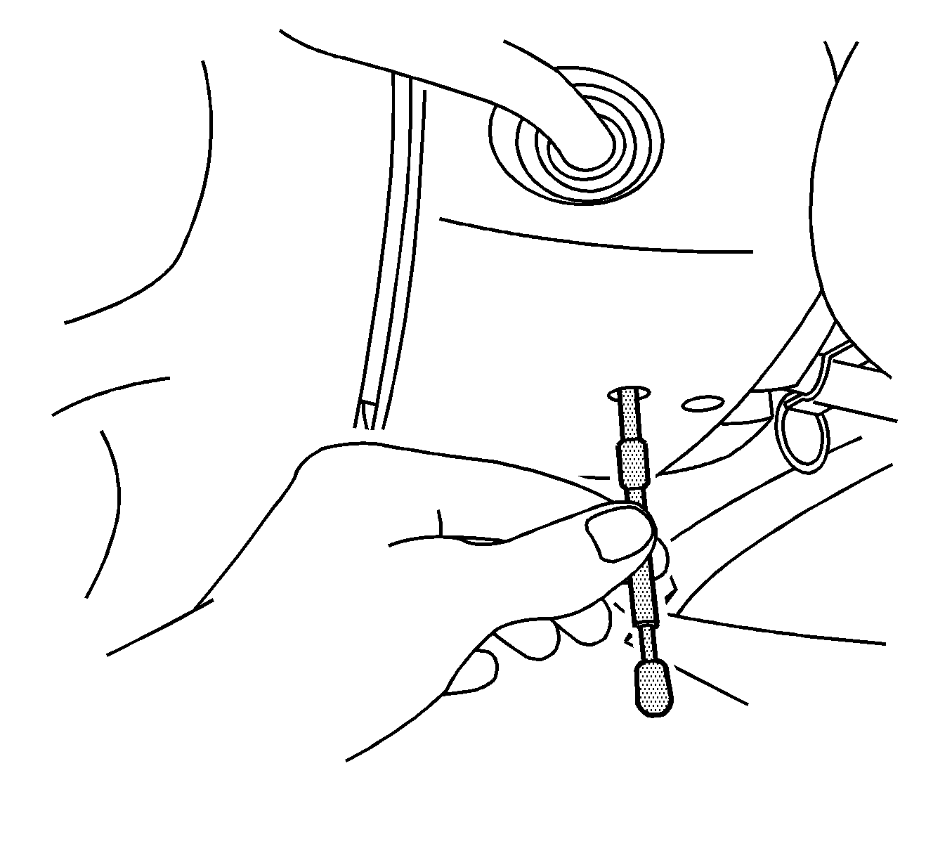
- Insert J 42640 into the steering column access hole in order to lock the steering column. This will maintain the correct orientation.
- Remove the steering wheel. Refer to Steering Wheel Replacement .
- Remove the SIR coil. Refer to Inflatable Restraint Steering Wheel Module Coil Replacement in SIR.
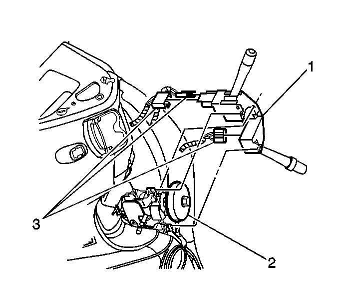
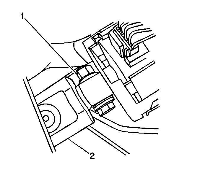
- Disconnect the electrical connectors (3) from the multifunction switch (1).
- Remove the driver's insulator panel. Refer to Instrument Panel Insulator Panel Replacement - Left Side in Instrument Panel, Gages, and Console.
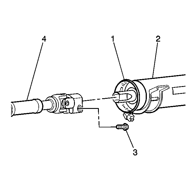
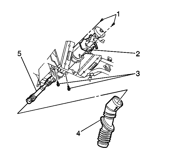
- Remove the upper pinch bolt (3) from the intermediate shaft (4).
- If equipped, remove the upper thru bolt (1) from the intermediate shaft (2).
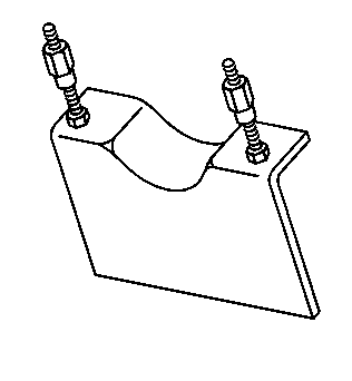
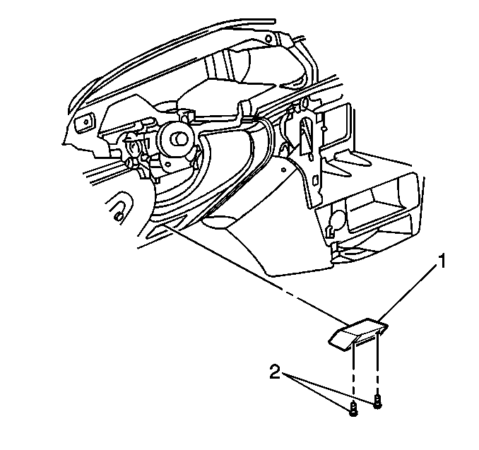
- Remove the 2 screws (2) and the lower air duct (1) from the instrument panel.
- Remove the steering column lower mounting bolts (3).
- Remove the steering column upper mounting bolts (1).
- Remove the steering column (2).
- Install the steering column onto J 41352 .
Notice: Once the steering column is removed from the vehicle, the column is extremely susceptible to damage. Dropping the column assembly on the end could collapse the steering shaft or loosen the plastic injections, which maintain column rigidity. Leaning on the column assembly could cause the jacket to bend or deform. Any of the above damage could impair the columns collapsible design. Do NOT hammer on the end of the shaft, because hammering could loosen the plastic injections, which maintain column rigidity. If you need to remove the steering wheel, refer to the Steering Wheel Replacement procedure in this section.
Notice: The wheels of the vehicle must be straight ahead and the steering column in the LOCK position before disconnecting the steering column or intermediate shaft from the steering gear. Failure to do so will cause the SIR coil assembly to become uncentered, which may cause damage to the coil assembly.
Notice: Once the steering column is removed from the vehicle, the column is extremely susceptible to damage. Dropping the column assembly on the end could collapse the steering shaft or loosen the plastic injections, which maintain column rigidity. Leaning on the column assembly could cause the jacket to bend or deform. Any of the above damage could impair the columns collapsible design. Do NOT hammer on the end of the shaft, because hammering could loosen the plastic injections, which maintain column rigidity. If you need to remove the steering wheel, refer to the Steering Wheel Replacement procedure in this section.
Installation Procedure
- Remove the steering column from J 41352 .
- Install the steering column (2).
- Install the lower mounting bolts (3) to the steering column.
- Install the upper mounting bolts (1) to the steering column.
- Install the SIR coil. Refer to Inflatable Restraint Steering Wheel Module Coil Replacement in SIR.
- Install the lower air duct (1) and the screws (2).
- Install the upper pinch bolt (3) to the intermediate shaft (4).
- If equipped, install the upper thru bolt (1) to the intermediate shaft (2).
- Install the driver insulator panel. Refer to Instrument Panel Insulator Panel Replacement - Left Side in Instrument Panel, Gages, and Console.
- Connect the electrical connectors (3) to the multifunction switch (1).
- Install the steering wheel. Refer to Steering Wheel Replacement .
- Enable the SIR system. Refer to SIR Disabling and Enabling in SIR.
Caution: In order to ensure the intended function of the steering
column in a vehicle during a crash and in order to avoid personal injury to
the driver, perform the following:
• Tighten the steering column lower fasteners before you tighten
the steering column upper fasteners. Failure to do this can damage the steering
column. • Tighten the steering column fasteners to the specified torque.
Overtightening the upper steering column fasteners could affect the steering
column collapse.
Notice: Refer to Fastener Notice in the Preface section.
Tighten
Tighten the bolts to 26 N·m (19 lb ft).
Tighten
Tighten the bolts to 26 N·m (19 lb ft).
Tighten
Tighten the screws to 2 N·m (18 lb in).
Tighten
Tighten the bolt to 62 N·m (46 lb ft).
Tighten
Tighten the thru bolt to 62 N·m
(46 lb ft).
