Air Conditioning Evaporator Core Replacement LHD
Removal Procedure
- Remove the HVAC module assembly. Refer to HVAC Module Assembly Replacement.
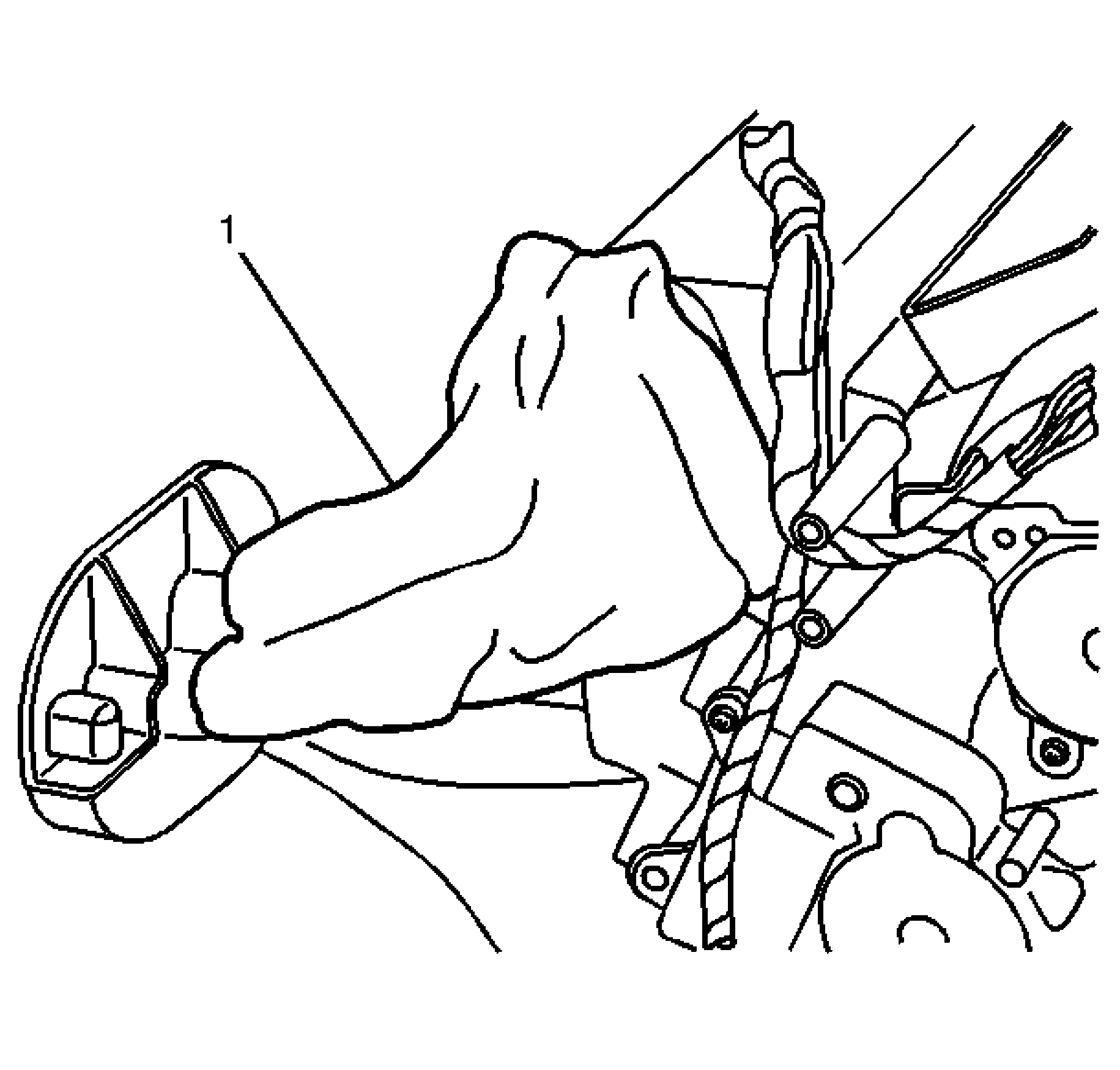
- Remove insulation (1) from pipe assembly.
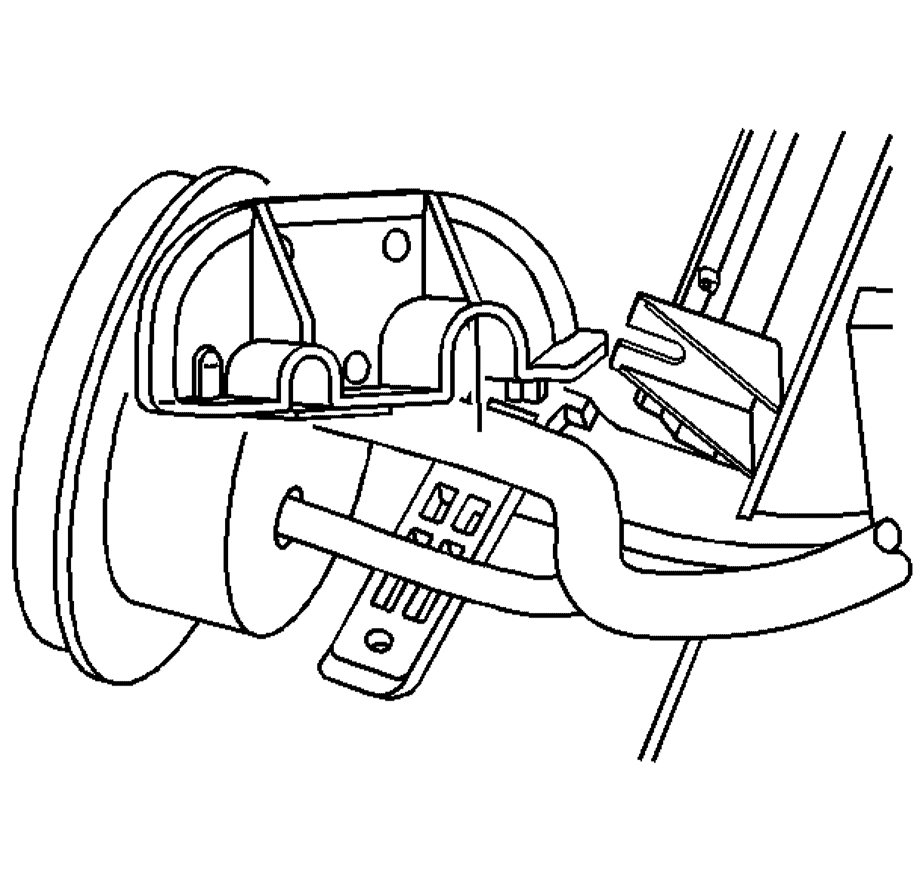
- Remove the HVAC line clamp screw.
- Remove the HVAC line clamp .
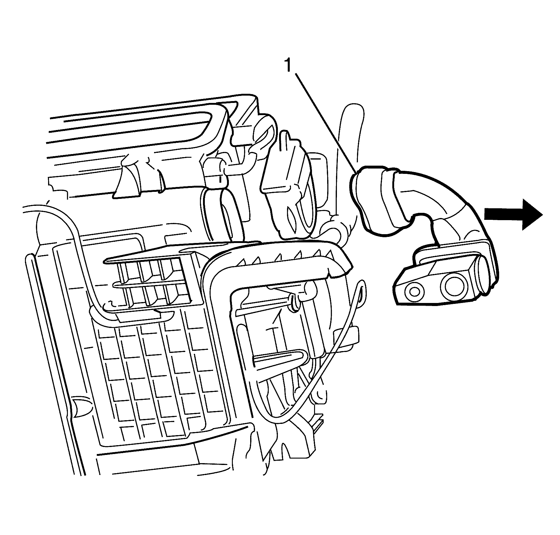
- Remove the pipes and TX valve (1) as a assembly.
- Remove the thermistor retainer.
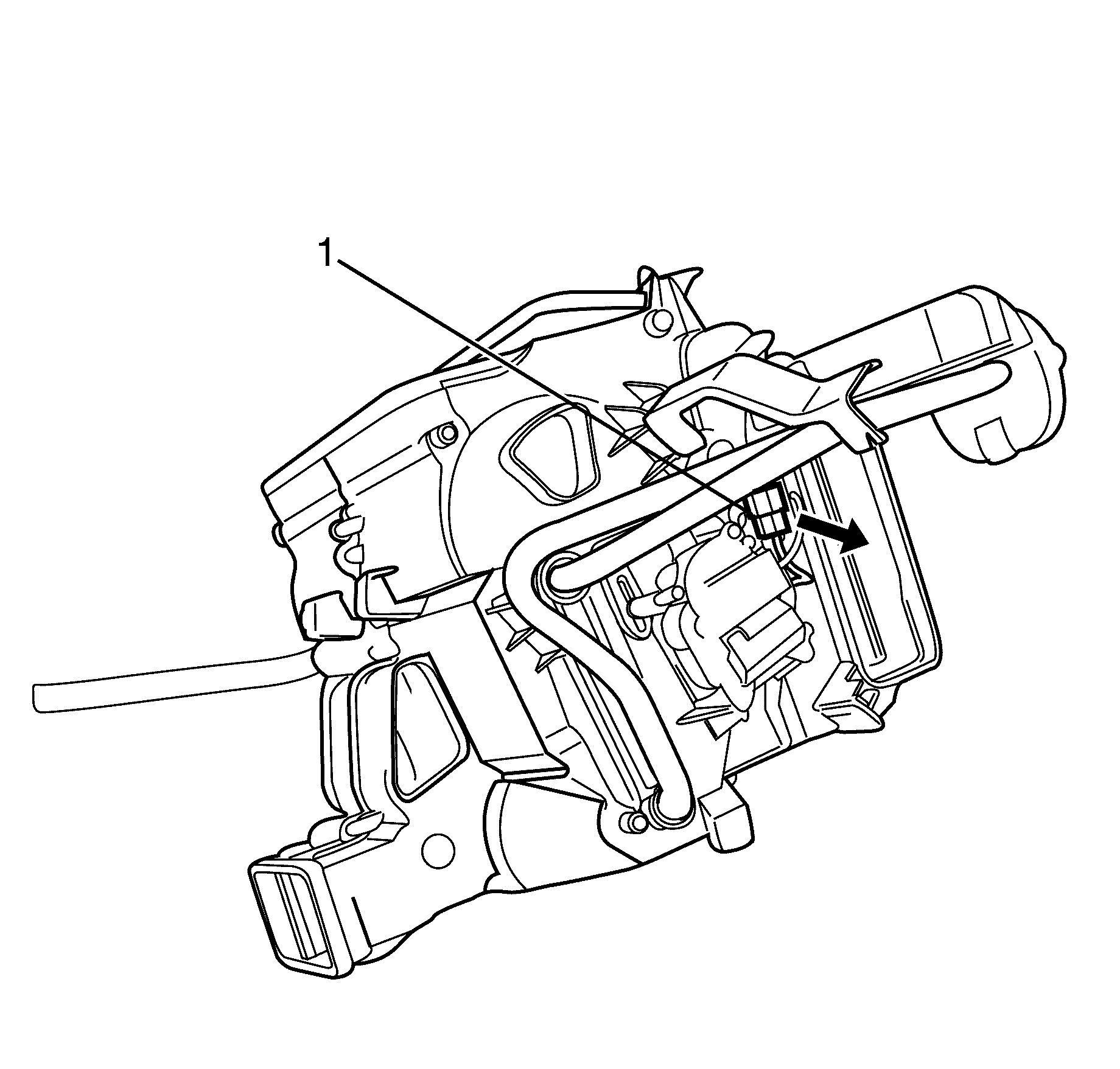
- Disconnect the thermistor electrical connector (1) from the HVAC module assembly retainer.
- Remove the blower module
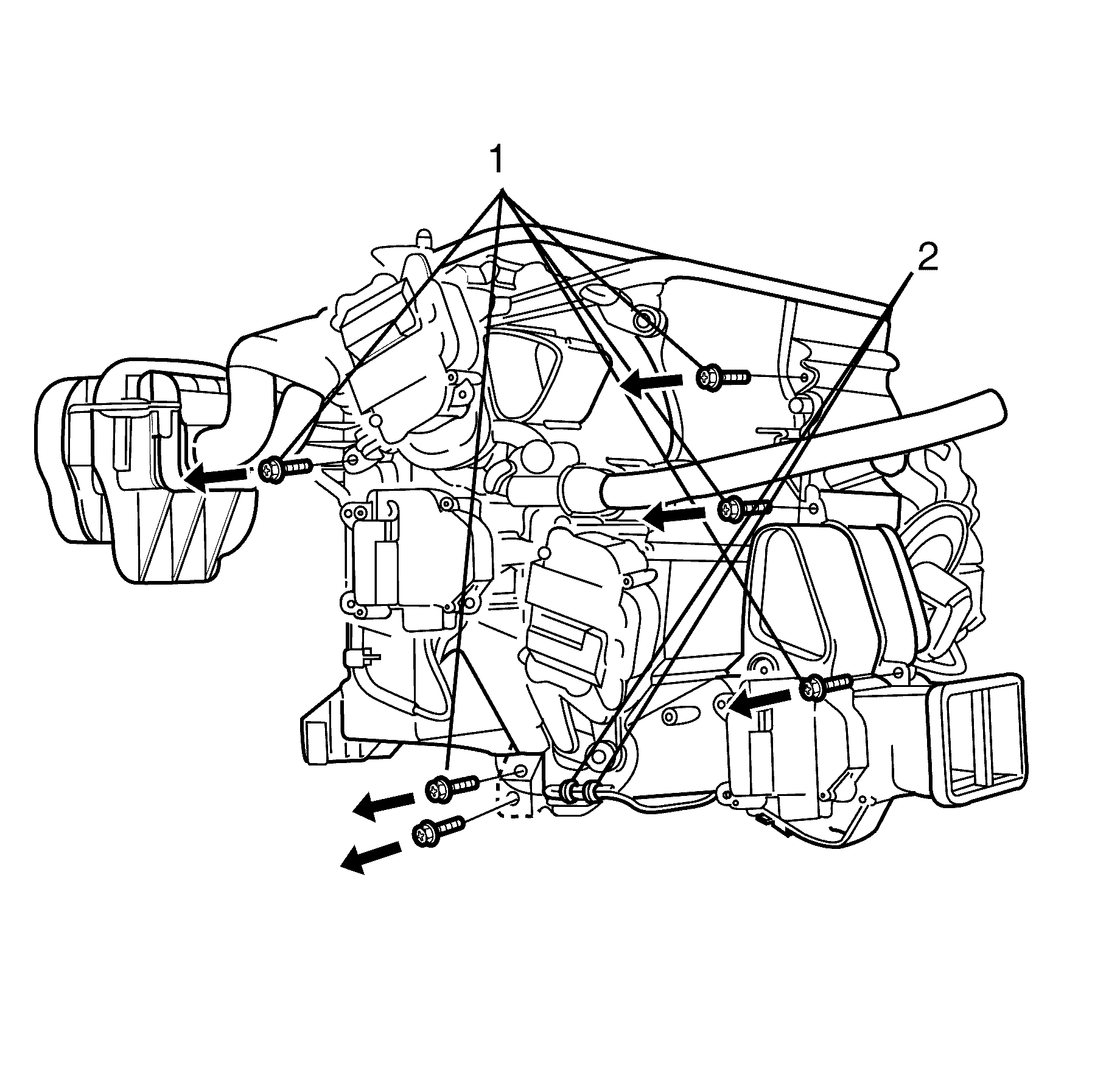
- Remove the seven screws (1) and two clips (2) that hold the HVAC case together.
- Separate the HVAC module assembly.
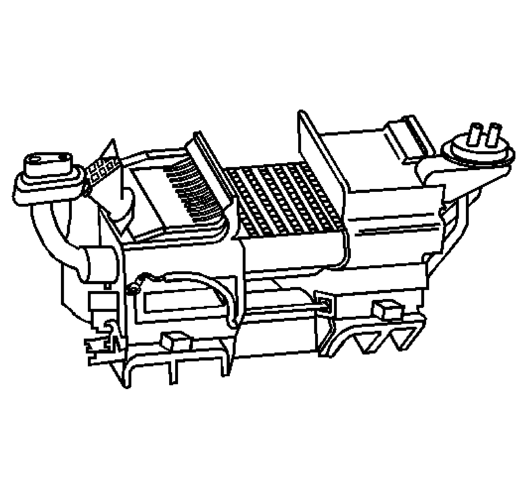
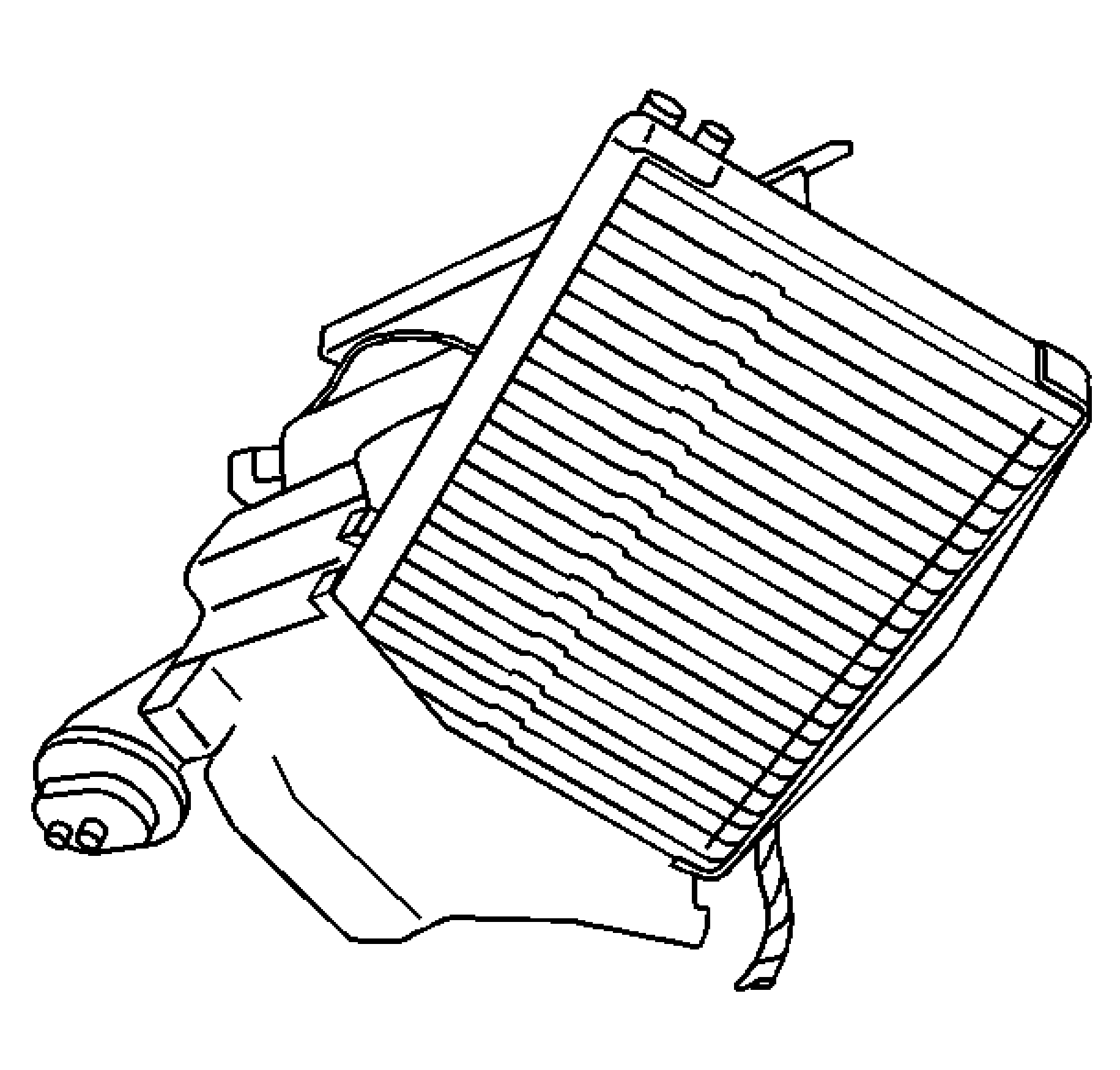
- Remove the evaporator core.
Installation Procedure
- Add refrigerant oil. Refer to Refrigerant System Capacities in Heating, Ventilation and Air Conditioning.
- Install NEW evaporator core seals to the evaporator.
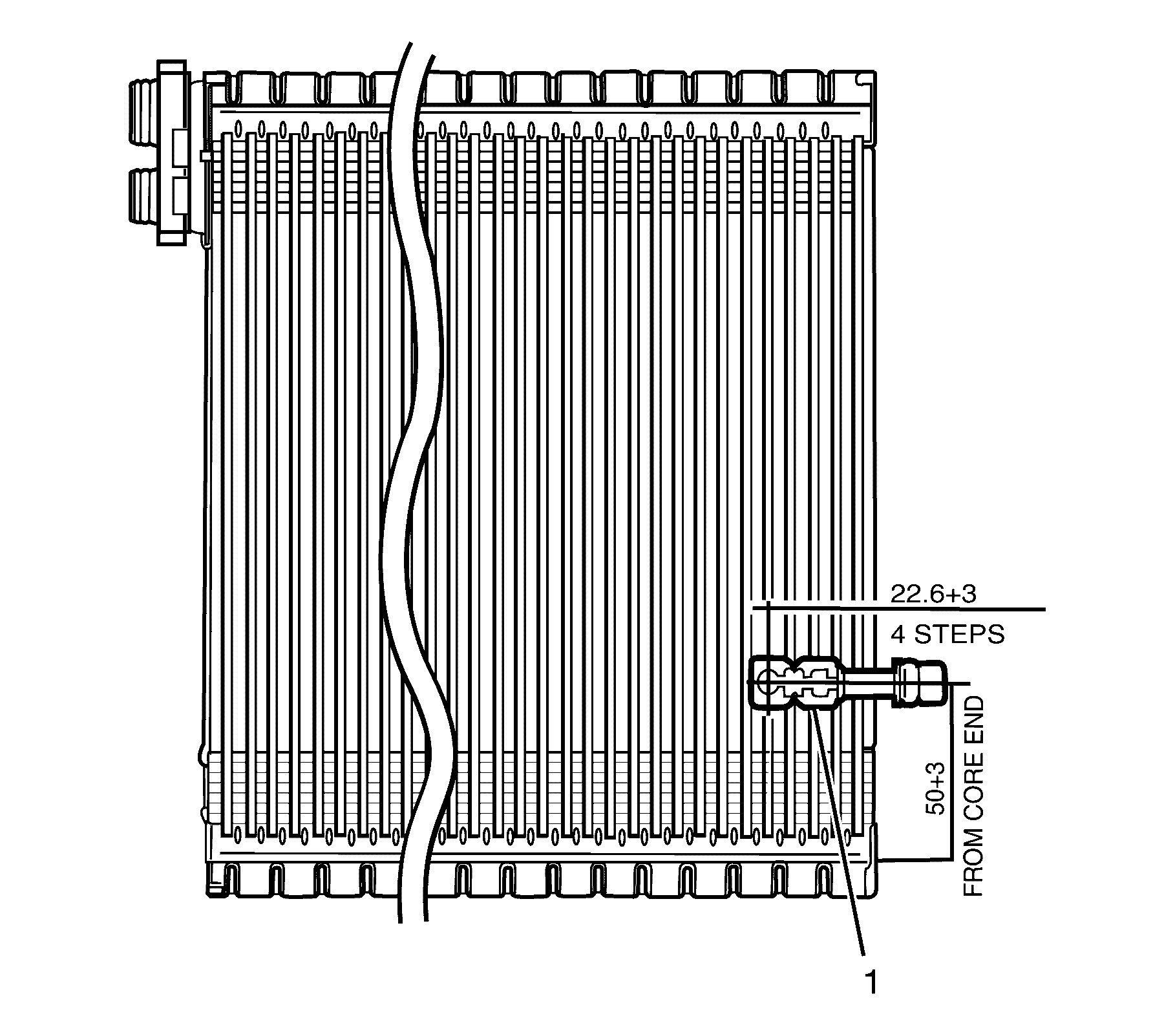
- Install thermistor (1) to the evaporator 22.6mm from the side of the evaporator and 50mm from the evaporator end.
- Install the evaporator core.
- Slide the HVAC module assembly case halves together.
- Install the screws that hold the case together.
- Install the front duct on the HVAC module assembly. Ensure that the retainers are properly engaged.
- Reposition the wire harness and connect the left hand and the auxiliary temperature actuator electrical connectors.
- Connect the thermistor electrical connector to the HVAC module assembly retainer.
- Install NEW O-rings to the evaporator core and the TX valve lines. Refer to O-Ring Replacement.
- Install the A/C lines into the TX valve.
- Carefully slide the TX valve onto the evaporator core until seated.
- Install the TX valve line bracket.
- Install the HVAC line clamp.
- Install the HVAC line clamp screw.
- Install the insulation (1) onto the lines and the TX valve.
- Install the HVAC module assembly. Refer to HVAC Module Assembly Replacement.

Important: DO NOT force the evaporator core into the HVAC module assembly. Damage to the thermistor can occur.

Important: Ensure that all of the temperature and mode doors align to their corresponding slots within the HVAC module assembly.
DO NOT force the HVAC module assembly case halves together. Install NEW tough seal every time case is split.Notice: Refer to Fastener Notice in the Preface section.
Tighten
Tighten the screws to 1 N·m (8 lb in).

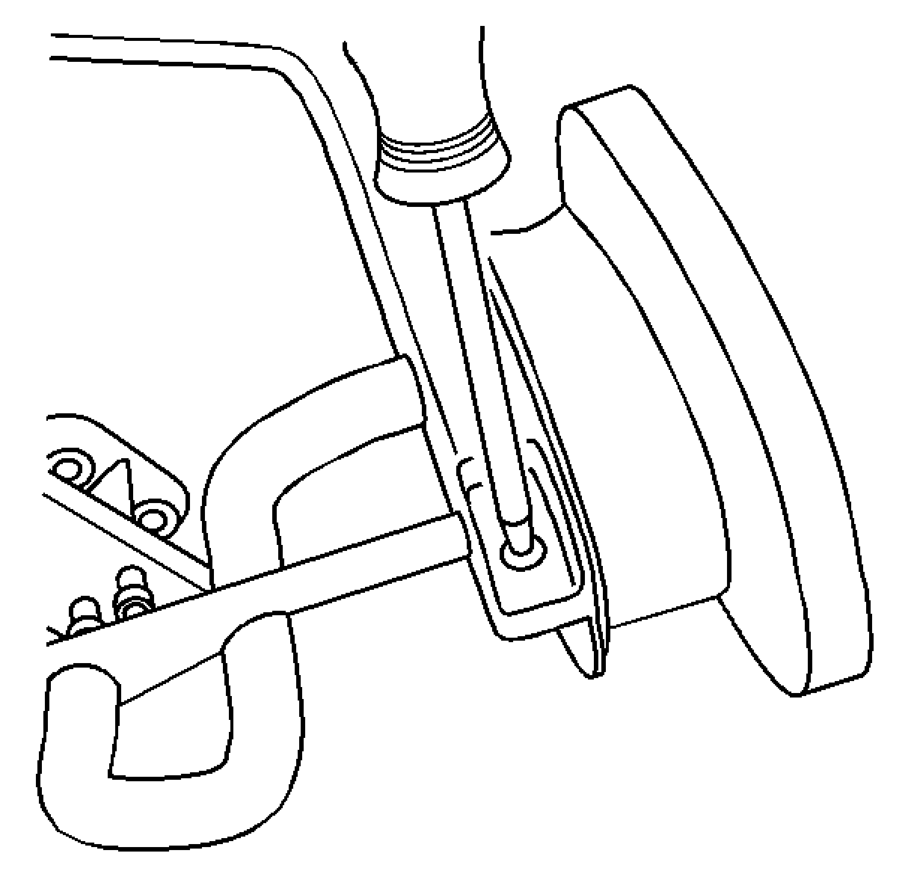
Tighten
Tighten the screw to 1 N·m (8 lb in).

Air Conditioning Evaporator Core Replacement RHD
Removal Procedure
- Remove the HVAC module assembly. Refer to HVAC Module Assembly Replacement.
- With the HVAC module assembly on a bench locate the thermal expansion (TX) valve retaining upper plastic cover (1).
- Remove the TX valve retaining upper plastic cover (1).
- Remove the air inlet assembly to HVAC module assembly retaining screws (1).
- Remove the air inlet assembly to HVAC module assembly retaining screws (1).
- Remove the air inlet assembly (3) from the HVAC module assembly (1).
- Remove the evaporator (1) from the HVAC module assembly (2).
- While the evaporator (1) is out of the HVAC module assembly (2), remove any contaminates from the housing such as hair, leaves or dust with a moist rag.
Caution: Refer to Safety Glasses Caution in the Preface section.
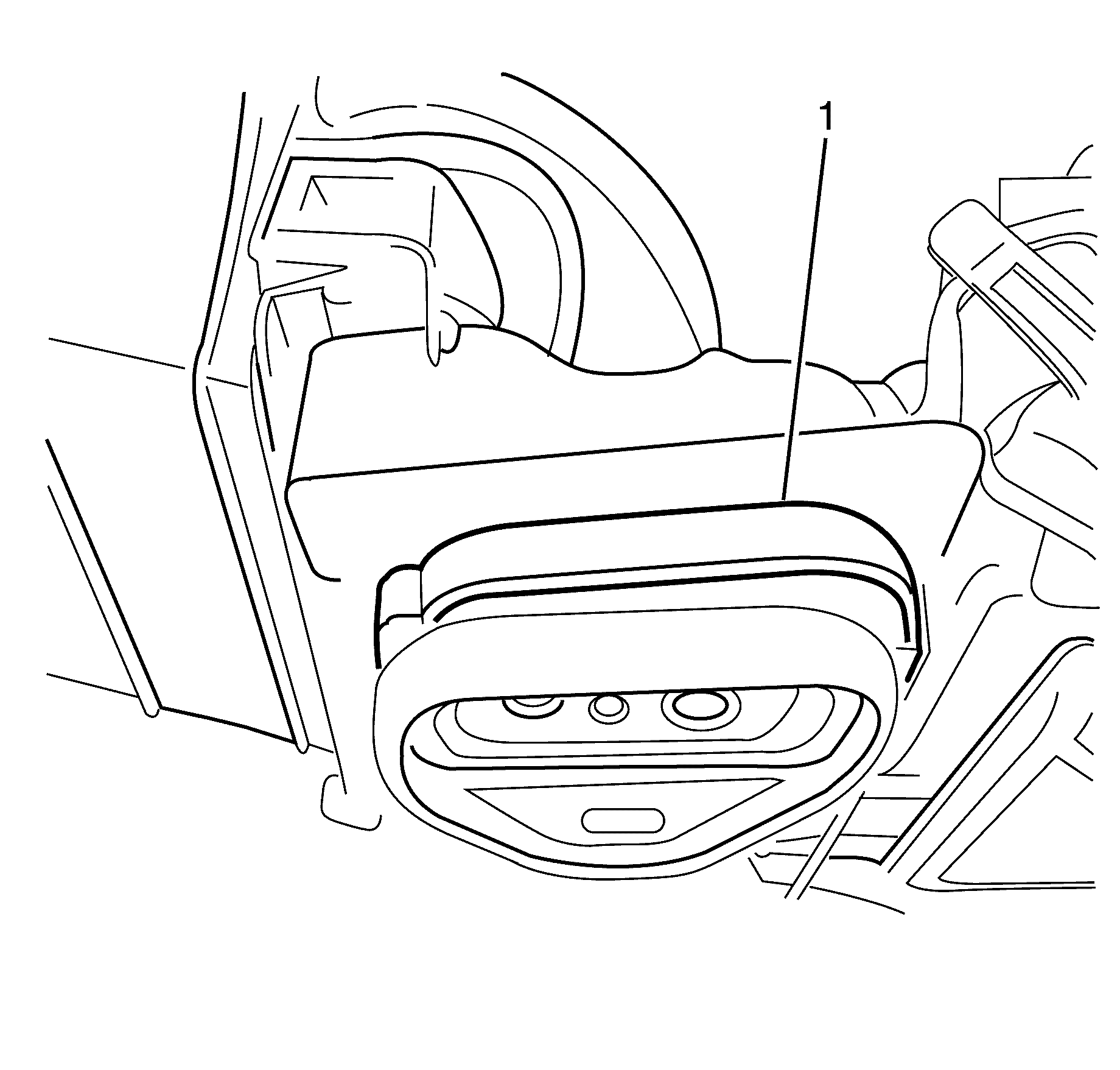
Important: Unclip the TX valve retaining upper plastic cover (1) and remove by lifting upwards.
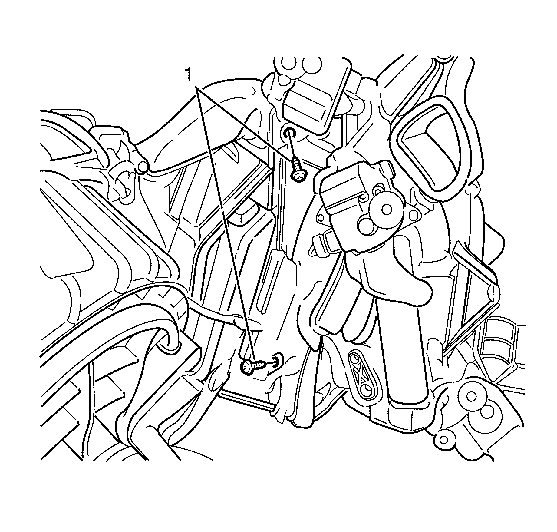
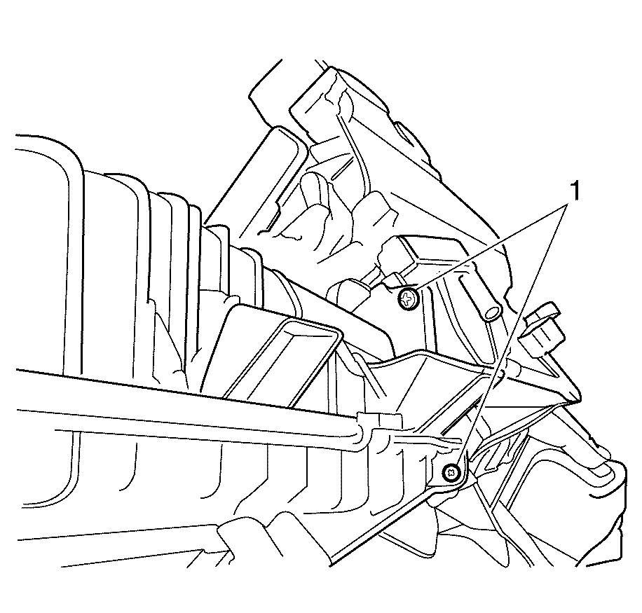
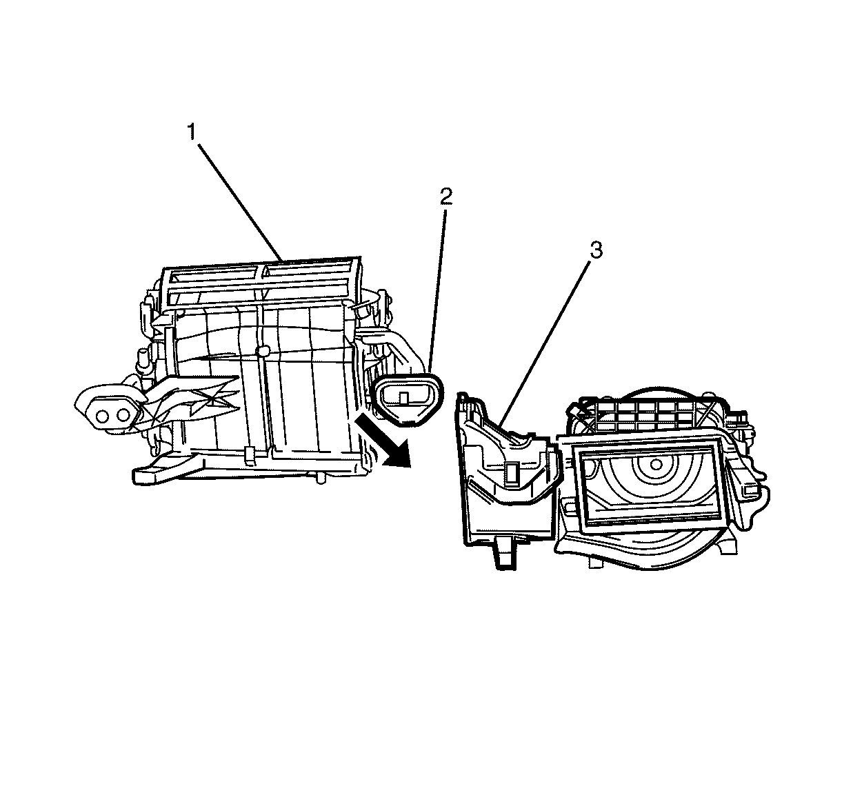
Important: Unclip the air inlet assembly (3) and carefully tilt downwards past the TX valve (2)
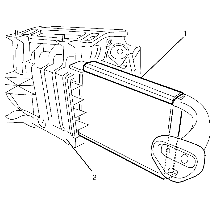
Important: Gently grasp the evaporator (1) pipes and slowly withdraw the evaporator from the HVAC module assembly (2).
Installation Procedure
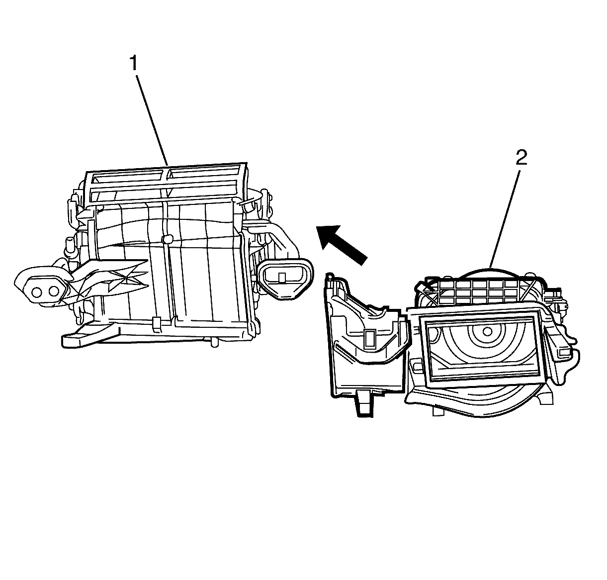
- Install the evaporator core (1) to the HVAC module assembly housing (2).
- Install the air inlet assembly (2) to the HVAC module assembly (1).
- Install the air inlet assembly to HVAC module assembly retaining screws (1).
- Install the air inlet assembly to HVAC module assembly retaining screws (1).
- Install the TX valve retaining upper plastic cover (1).
- Install the HVAC module assembly. Refer to HVAC Module Assembly Replacement.

Important: Install the evaporator core (1) by gently sliding into HVAC module assembly housing (2).
Notice: Refer to Fastener Notice in the Preface section.

Tighten
Tighten the screws to 1 N·m (8 lb
in.)

Tighten
Tighten the screws to 1 N·m (8 lb
in.)

Important: Make sure all the clips on the thermal expansion (TX) valve retaining upper plastic cover (1) are engaged to avoid an induced rattle condition.
