Tools Required
EN 46114 Engine Lift Bracket
Removal Procedure
- Remove the engine dress cover. Refer to Engine Cover Replacement for 3.6L Engines or Engine Cover Replacement for 6.0L Engines.
- Remove the radiator air baffle. Refer to Radiator Air Upper Baffle and Deflector Replacement .
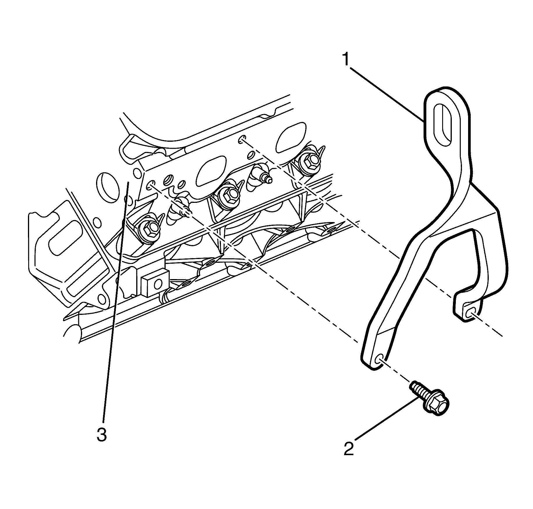
- Position the EN 46114 (1) on the cylinder head (2).
- Install the EN 46114 to cylinder head retaining bolts (3).
- Install a suitable lifting tool and raise the engine assembly until the engine mount brackets (1) are clear of the engine mount retainers (2).
- Raise and support the vehicle. Refer to Lifting and Jacking the Vehicle .
- Remove the front bumper fascia. Refer to Front Bumper Fascia Replacement .
- Remove the front air deflector. Refer to Front Air Deflector Replacement .
- Remove the splash shield. Refer to Engine Splash Shield Replacement .
- Remove the front control arm. Refer to Control Arm Replacement .
- Remove the front castor arm. Refer to Front Lower Control Front Arm Replacement .
- Remove the stabilizer shaft link. Refer to Stabilizer Shaft Link Replacement .
- Remove the steering gear to subframe retaining bolts (1).
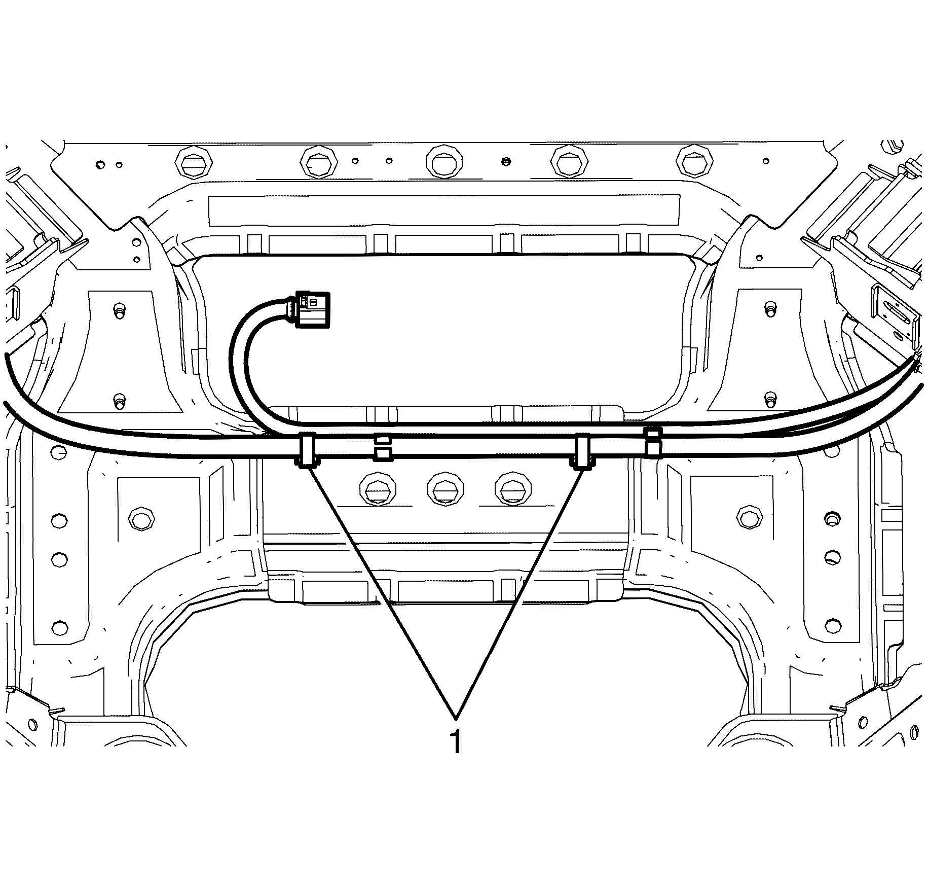
- Disconnect the electrical harness retainers (1) securing the engine harness to the frame.
- Secure the radiator to the radiator upper mounting brackets.
- Install a suitable bench trolley under the frame.
- Lower the vehicle to the frame support table.
- Remove the front sub frame to front chassis rail retaining bolts (2).
- Carefully raise the body from the frame.
- Make sure when raising the body the following items are clear from the frame.
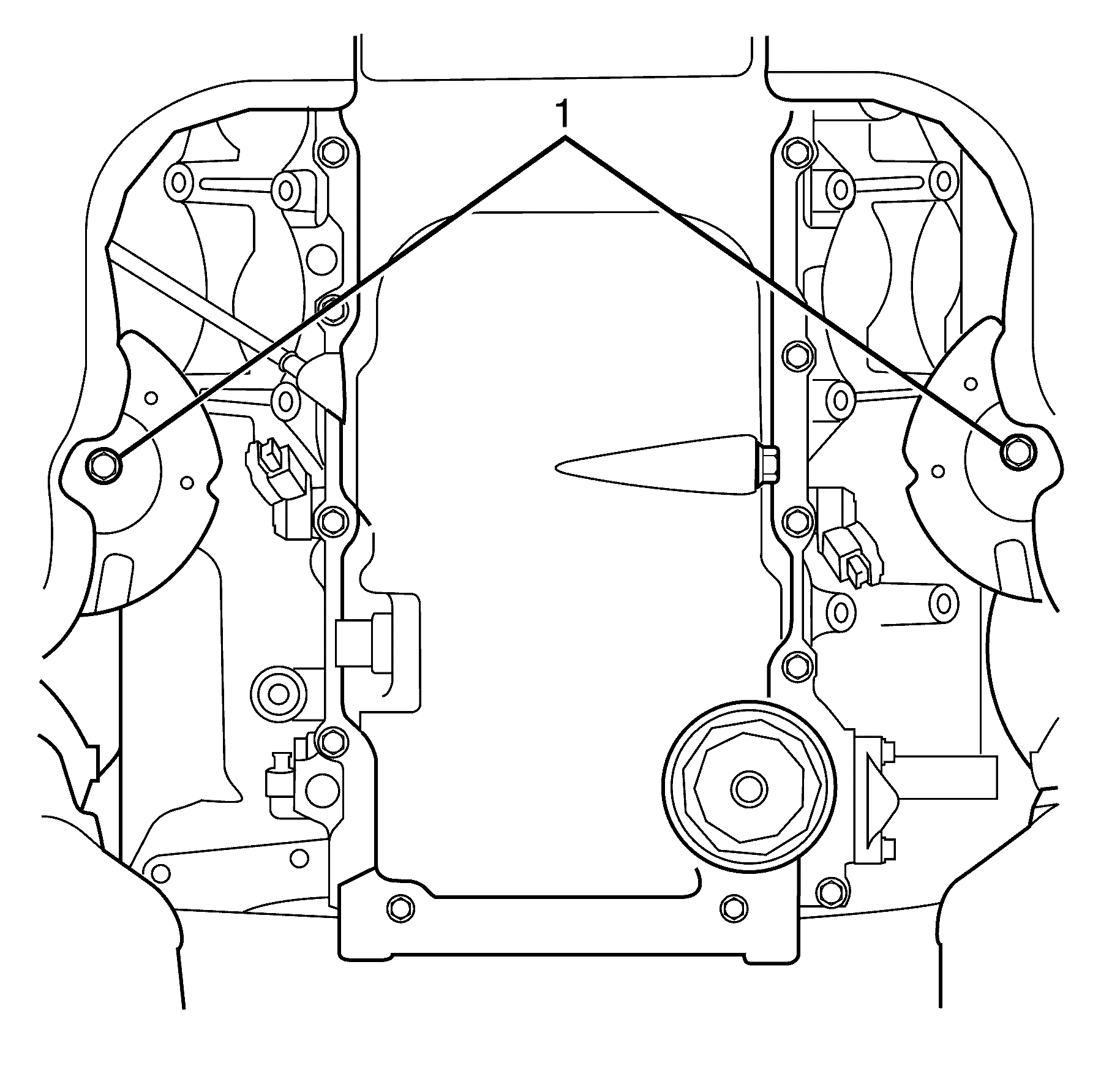
- Remove the lower engine mount to front sub frame retaining nuts (1).
- Remove the stabliser bar insulator bracket to subframe retaining nuts (3) on both sides of the stabiliser bar (4). Repeat for the opposite side.
- Remove the stabliser bar insulator bracket (2) from the subframe (1) on both sides of the stabiliser bar.
- Remove the stabliser bar from the front subframe.
- With the aid of an assistant, remove the frame from the support fixture.
Caution: Refer to Safety Glasses Caution in the Preface section.
Caution: Refer to Vehicle Lifting Caution in the Preface section.
Notice: Refer to Fastener Notice in the Preface section.
Tighten
Tighten the
EN 46114
to cylinder head retaining bolts (3) to 50 N·m (36 lb ft).
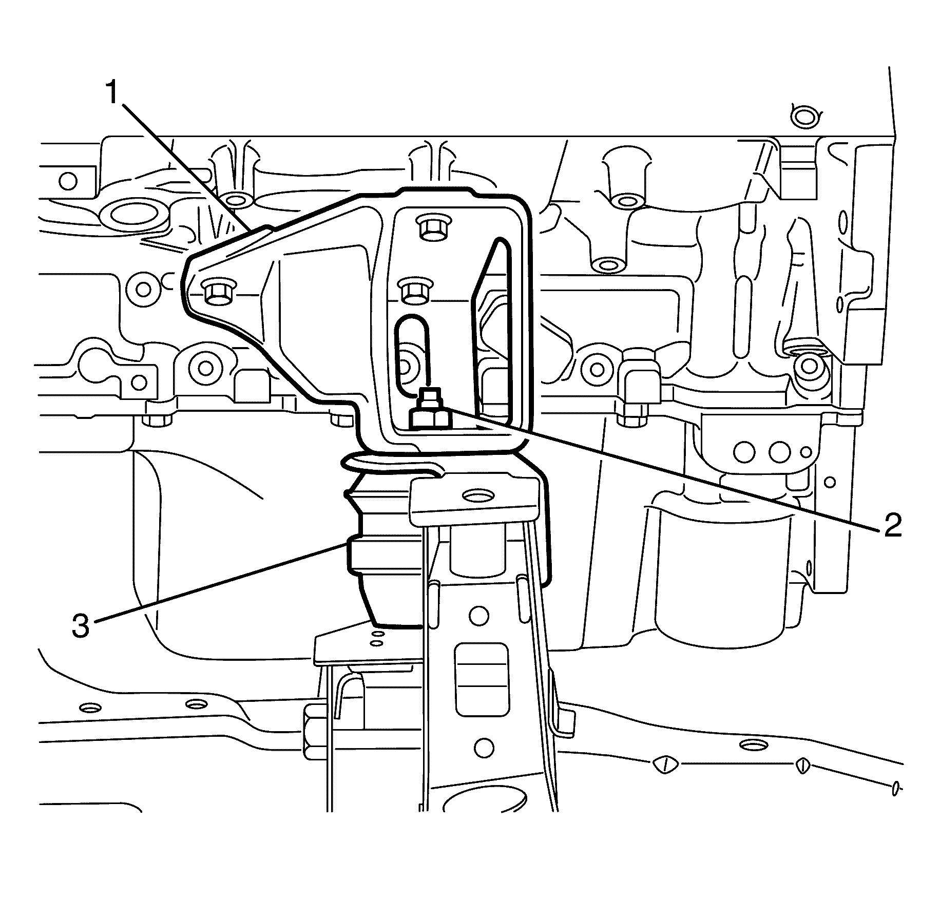
Important: When lifting the engine assembly, observe the clearance between the rear of the engine assembly and the dash panel.
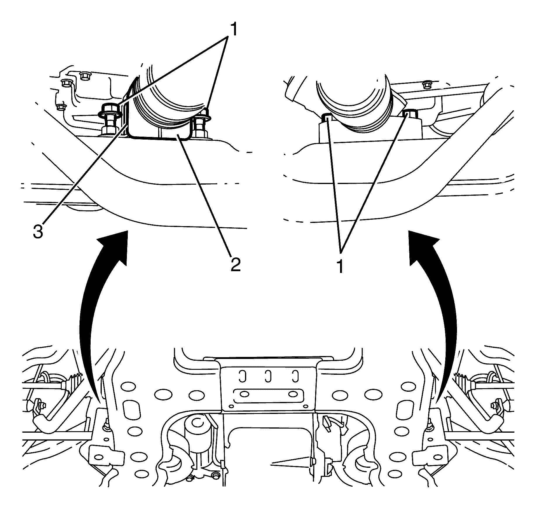
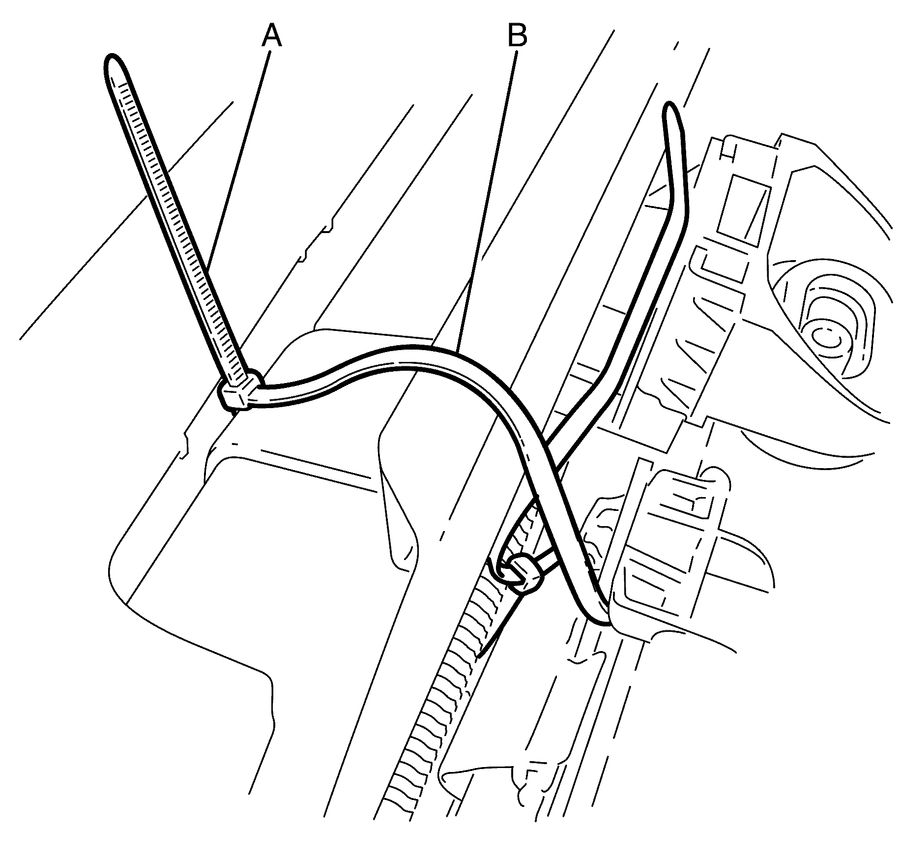
Important: It is necessary to secure the radiator to the front end assembly, as the radiator is supported by the subframe.
Important: Thread zip tie A around the front end assembly and zip tie B through the radiator and condenser mount. Insert zip tie A into the retainer of zip tie B and insert zip tie B into the retainer of zip tie A.
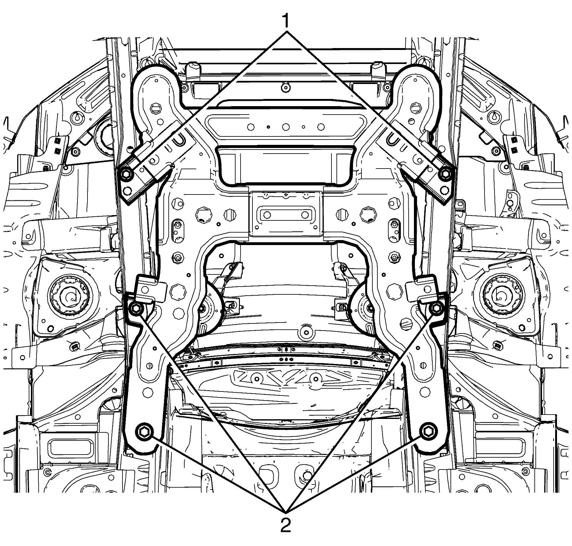
| • | The brake pipes |
| • | The steering knuckle assembly |
| • | The wheel speed sensor electrical harness |
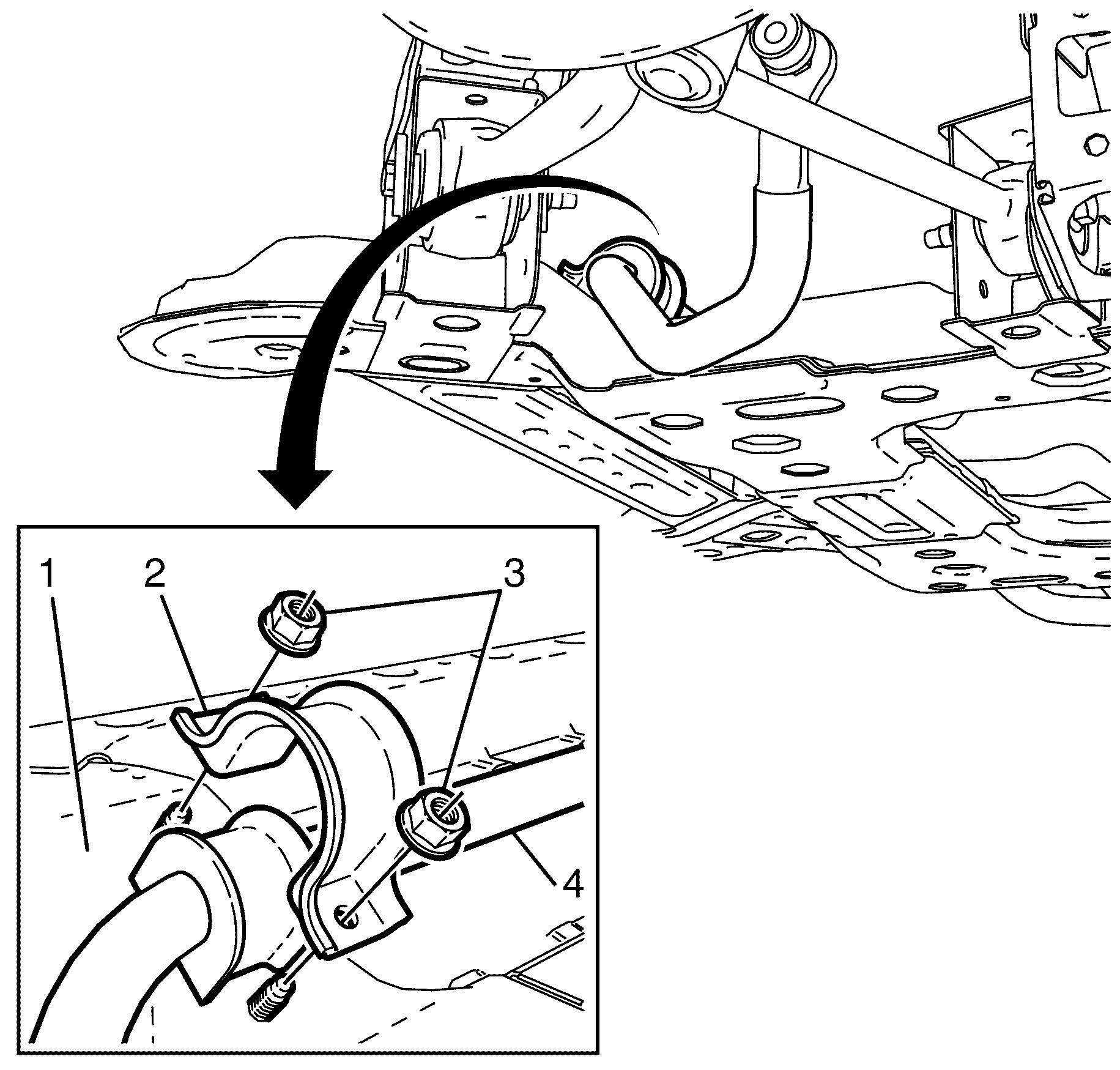
Important: Nuts with micro-encapsulated thread sealant must be discarded after removal.
Discard the nuts.
Installation Procedure
- With the aid of an assistant, install the frame to the support fixture.
- Install the stabilizer bar to the front subframe.
- Install the stabilizer bar caps (2) to the front subframe
- Install NEW stabilizer shaft to front sub frame retaining nuts (3).
- Install the engine mount to the front subframe.
- Install the lower engine mount to front sub frame retaining nuts (2).
- Carefully lower the body to the frame.
- Make sure the following components are clear from the frame.
- Install the front sub frame to front chassis rail retaining bolts (1 and 2).
- Raise the vehicle.
- Remove the suitable bench trolley from under the vehicle.
- Lower the engine and remove the suitable lifting tool from the engine.
- Install the lower engine mount to front sub frame retaining nuts (2).
- Cut zip tie A around the front end assembly and zip tie B through the radiator and condenser mount.
- Secure the engine electrical harness retainers (1) to the frame.
- Install the steering gear insulator (3) to the steering gear.
- Install the steering gear insulator retaining bracket (2) to the steering gear insulator (3).
- Install the steering gear to subframe retaining bolts (1).
- Install the stabilizer shaft link. Refer to Stabilizer Shaft Link Replacement .
- Install the front castor arm. Refer to Front Lower Control Front Arm Replacement .
- Install the front control arm. Refer to Control Arm Replacement .
- Install the splash shield. Refer to Engine Splash Shield Replacement .
- Install the front air deflector. Refer to Front Air Deflector Replacement .
- Install the front bumper fascia. Refer to Front Bumper Fascia Replacement .
- Lower the suitable lifting tool until the engine mount brackets are located on the engine mount retainers.
- Remove the EN 46114 to cylinder head retaining bolts (3).
- Remove the EN 46114 (1) from the cylinder head (2).
- Install the radiator air baffle. Refer to Radiator Air Upper Baffle and Deflector Replacement .
- Install the engine dress cover. Refer to Engine Cover Replacement for 3.6L Engines or Engine Cover Replacement for 6.0L Engines.
- Align the vehicle. Refer to Wheel Alignment Measurement .

Important: Do not fully tighten the stabilizer shaft retaining bolts to the frame at this stage.
Do not fully tighten at this stage.
Do not fully tighten at this stage.
| • | The wheel speed sensor electrical harness |
| • | The steering knuckle assembly |
| • | The brake pipes |
Notice: Refer to Fastener Notice in the Preface section.

Tighten
Tighten the bolts to 95 N·m (70 lb ft).

Tighten
Tighten the retaining nuts to 80 N·m
(59 lb ft).


Tighten
Tighten the retaining bolts to 65 N·m
(48 lb ft).

Important: When lifting the engine assembly, observe the clearance between the rear of the engine assembly and the dash panel.

