Tools Required
CH-49405 Ball Joint Release Tool.
Removal Procedure - Up to xx/xx
- Raise and support the vehicle. Refer to Lifting and Jacking the Vehicle.
- Remove the front wheel. Refer to Tire and Wheel Removal and Installation.
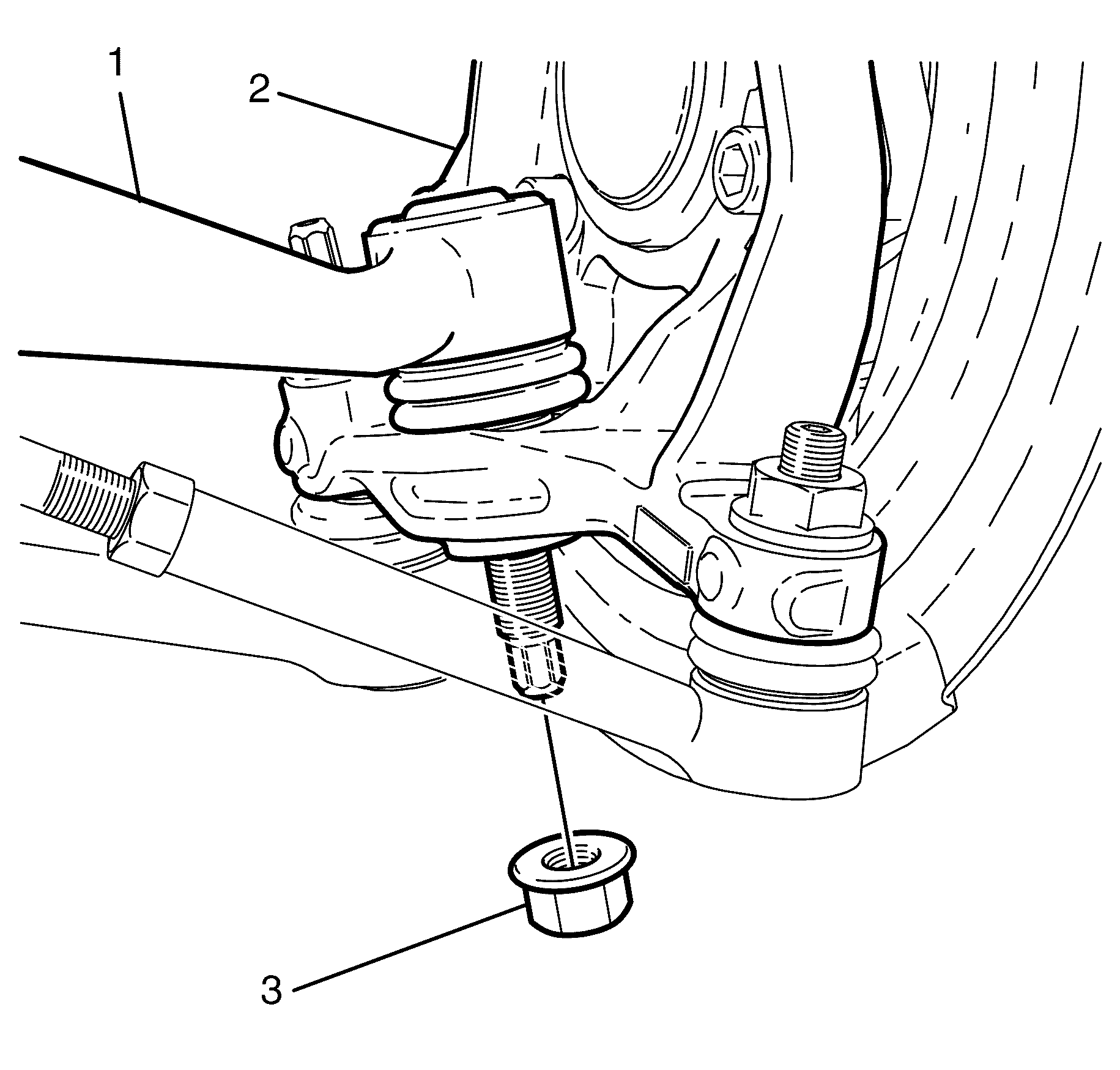
- Remove the front caster arm to steering knuckle retaining nut (1).
- Separate the front caster arm (1) from the steering knuckle (3) using the CH-49405 (2).
- Disconnect the front caster arm (1) from the steering knuckle (3).
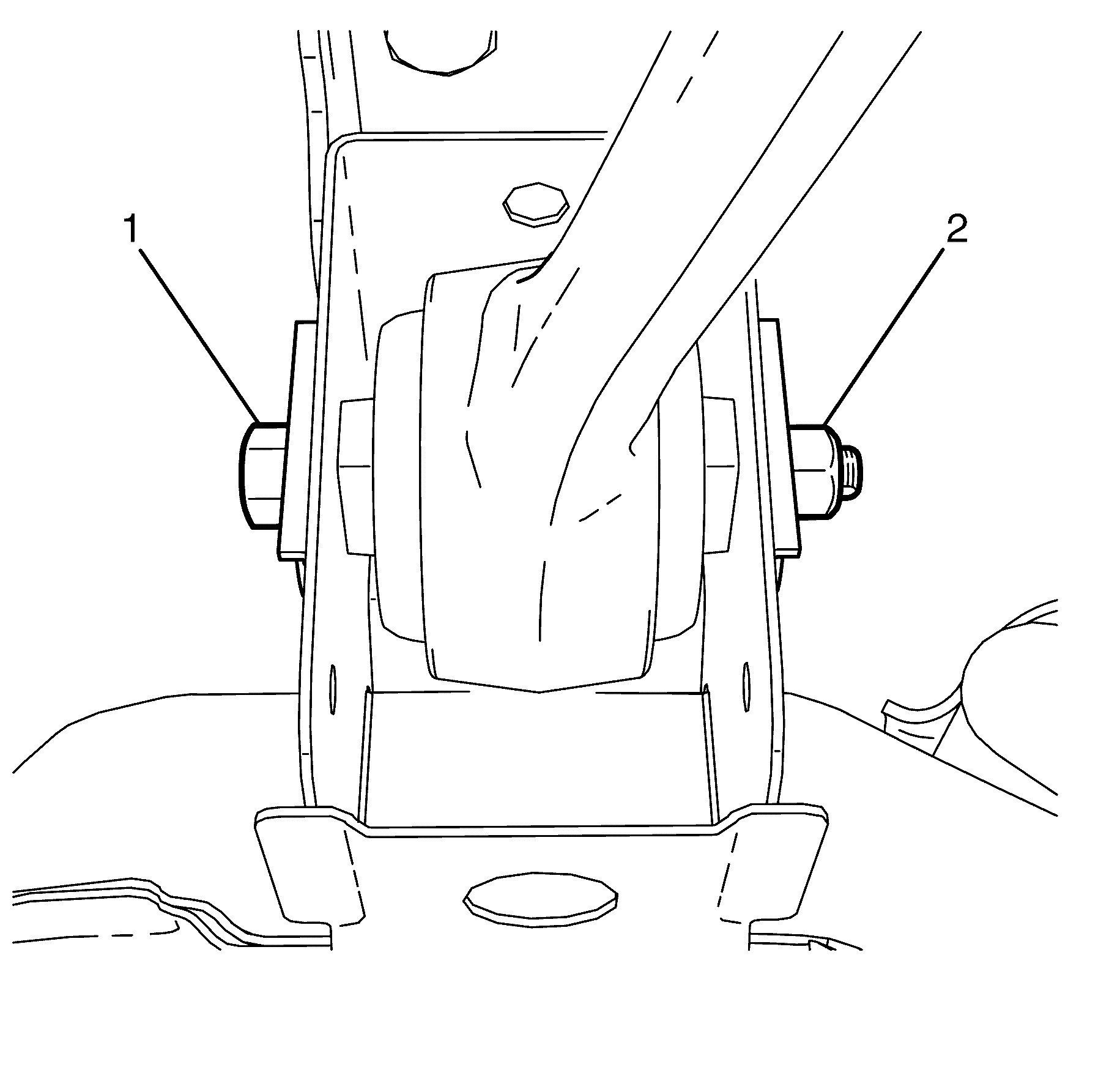
- Remove the front caster arm to subframe retaining nut (4).
- Remove the front caster arm to subframe retaining bolt (2).
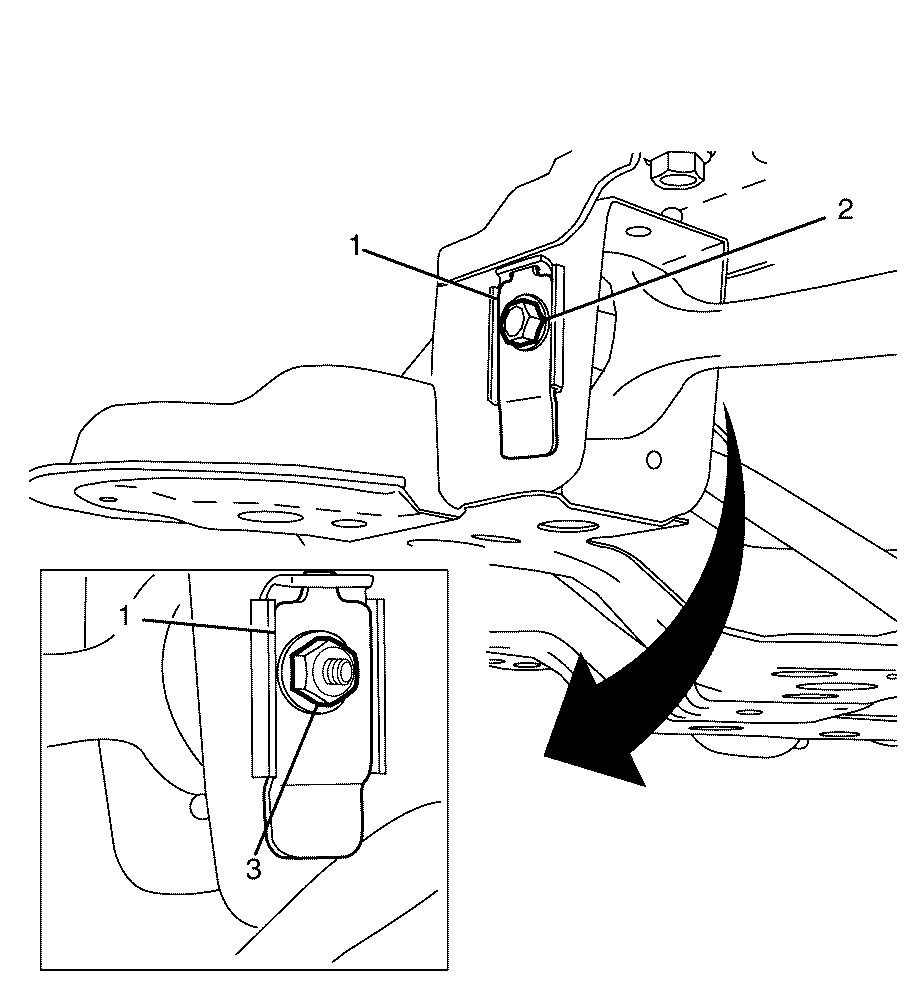
- Mark the front caster arm to subframe offset washers (1) to reference the side facing out.
- Remove the subframe offset washer to subframe retaining clips (3).
- Remove the subframe offset washers (1).
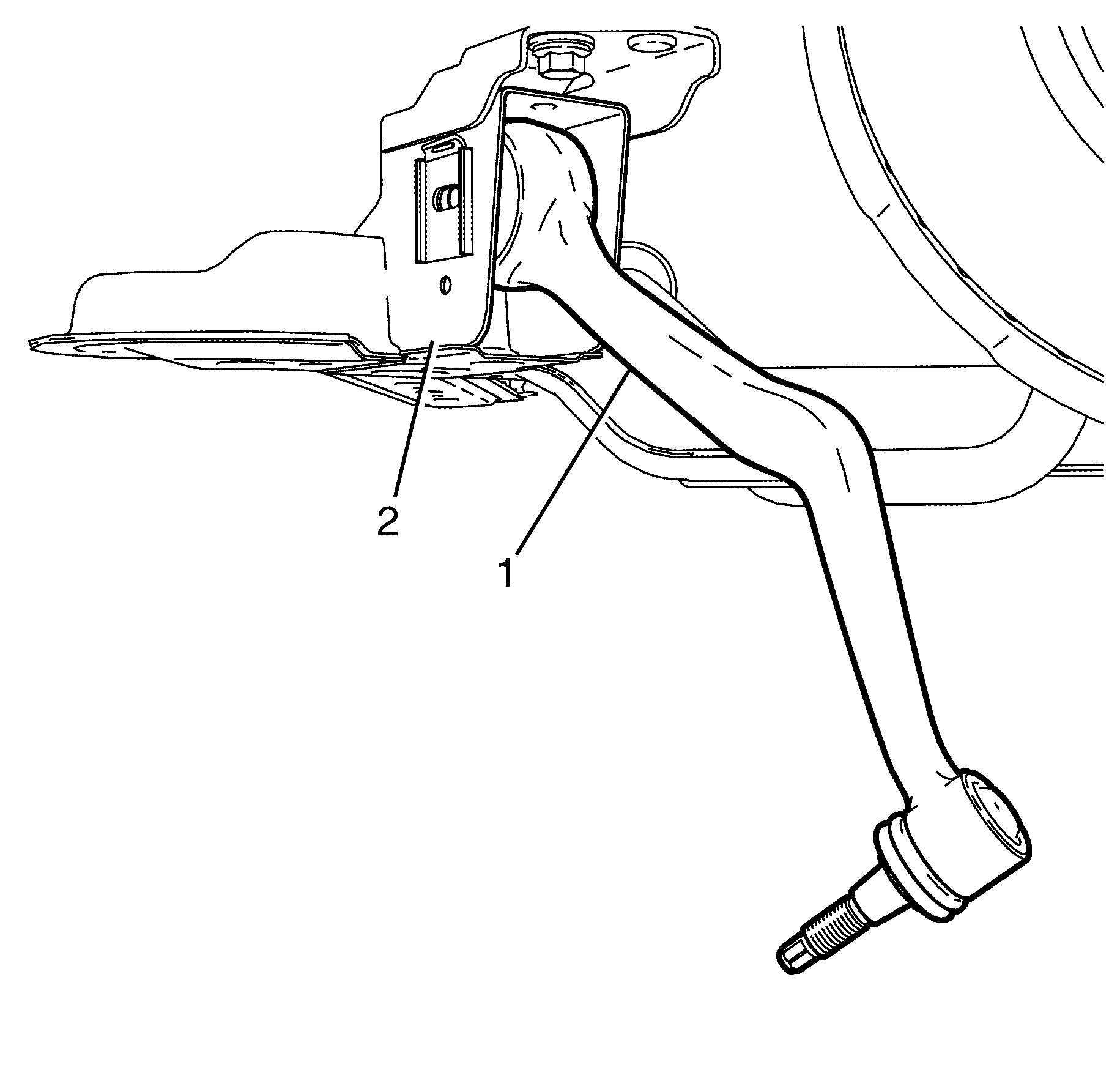
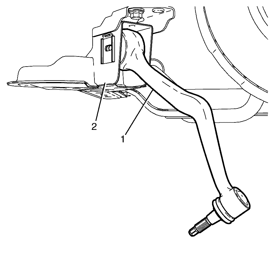
- Remove the front caster arm (1) from the subframe (2).
- Inspect all parts for wear and damage.
Caution: Refer to Safety Glasses Caution in the Preface section.
Caution: Refer to Vehicle Lifting Caution in the Preface section.
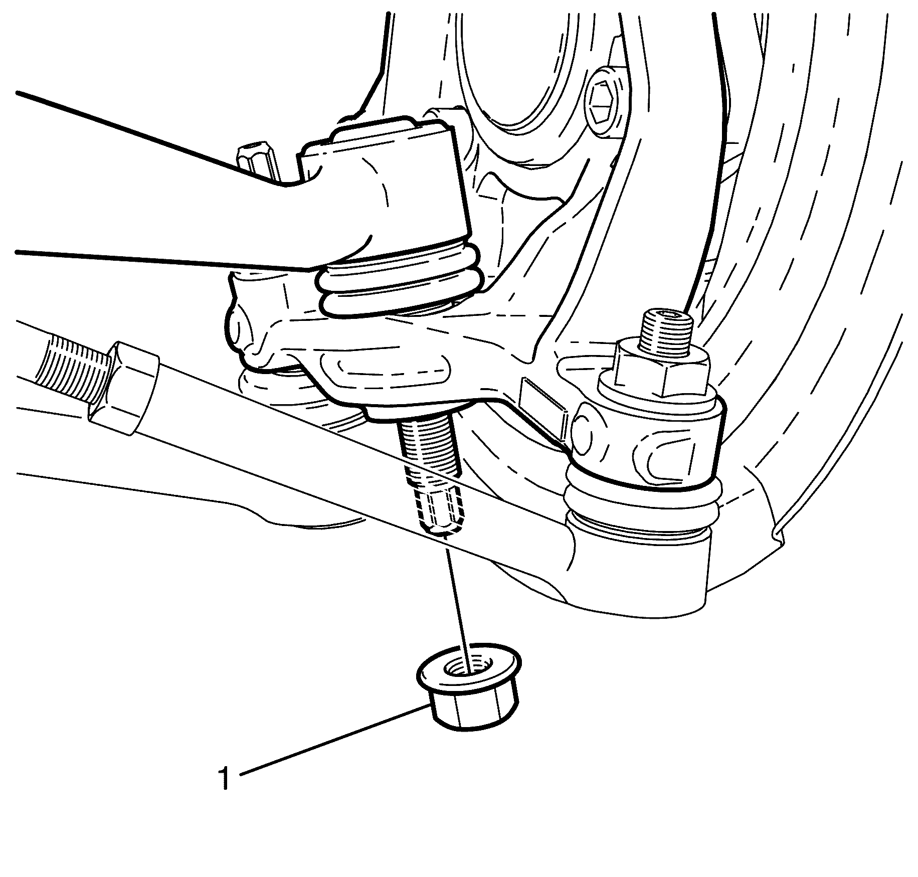
Important: Nuts with micro-encapsulated thread sealant must be discarded after removal.
Discard the nut.
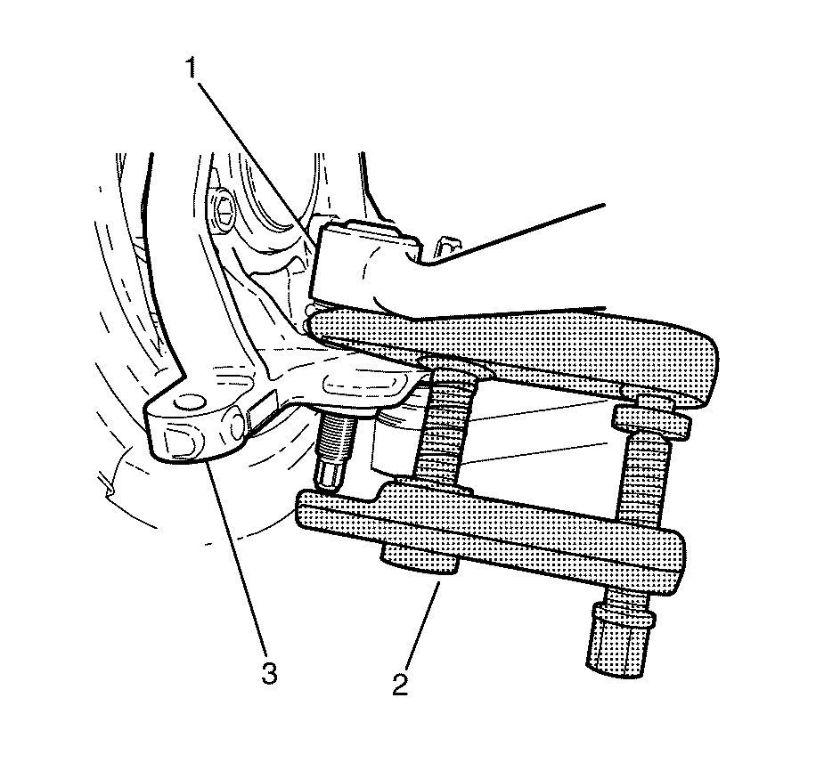
Important: Once a load is applied by the release tool loading bolt, a quick tap on the nut end of the tool will reduce the separating force required.
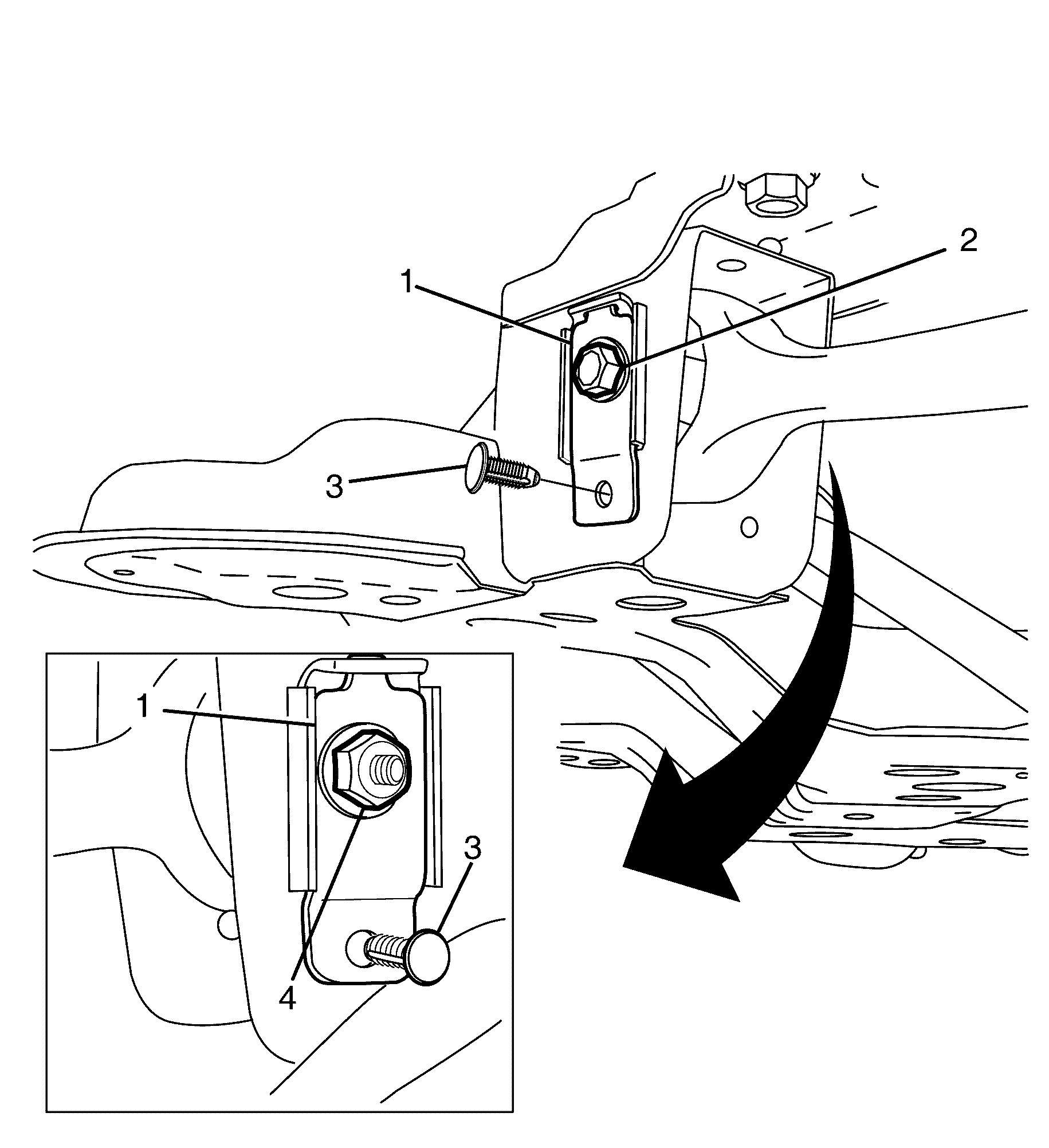
Discard the nut.
Discard the bolt.
Important: The front caster arm to subframe offset washers (1) are used to adjust the caster of the front suspension.
Installation Procedure - Up to xx/xx
- Install the front caster arm (1) from the subframe (2).
- Install the front caster arm to subframe offset washers (1).
- Install the subframe offset washer to subframe retaining clips (3).
- Install the NEW lower caster arm to the subframe retaining bolt (2).
- Install the NEW lower caster arm to the subframe retaining nut (4).
- Install the front caster arm ball joint (1) to the steering knuckle (2).
- Install the NEW front caster arm to steering knuckle retaining nut (3).
- Install the front wheel. Refer to Tire and Wheel Removal and Installation.
- Remove the safety stands.
- Lower the vehicle to the ground.
- Bounce the vehicle several times to settle the suspension.
- Check and adjust the wheel alignment. Refer to Wheel Alignment Measurement in Wheel Alignment.
- Tighten the front caster arm to subframe retaining bolt (1).


Important: The front caster arm to the subframe offset washers (1) are used to adjust the caster of the front suspension.
Important: The front caster arm to subframe retaining bolt (2), offset washers (1) and nut (4) must not be fully tightened at this stage.
Do not fully tighten at this stage.
Notice: Refer to Fastener Notice in the Preface section.
Tighten
Tighten the bolts a first pass to 40 N·m
(30 lb ft).
Tighten
Tighten the bolts an additional 60 degrees.
Important: The weight of the vehicle must be on a level surface and on all four wheels before fully tightening the bolts and nuts that have been partially tightened. Failure to comply with to this requirement may adversely affect the ride and handling characteristics of the vehicle and reduce bushing life.
Tighten
Tighten the bolts a first pass to 50 N·m
(30 lb ft).
Tighten
Tighten the bolts an additional 120 degrees.
Removal Procedure - From xx/xx
- Raise and support the vehicle. Refer to Lifting and Jacking the Vehicle.
- Remove the front wheel. Refer to Tire and Wheel Removal and Installation.
- Remove the front caster arm to steering knuckle retaining nut (1).
- Separate the front caster arm (1) from the steering knuckle (3) using the CH-49405 (2).
- Disconnect the front caster arm (1) from the steering knuckle (3).
- Remove the front caster arm to subframe retaining nut (3).
- Remove the front caster arm to subframe retaining bolt (2).
- Remove the front caster arm (1) from the subframe (2).
- Inspect all parts for wear and damage.
Caution: Refer to Safety Glasses Caution in the Preface section.
Caution: Refer to Vehicle Lifting Caution in the Preface section.

Important: Nuts with micro-encapsulated thread sealant must be discarded after removal.
Discard the nut.

Important: Once a load is applied by the release tool loading bolt, a quick tap on the nut end of the tool will reduce the separating force required.
Discard the nut.
Discard the bolt.
Installation Procedure - From xx/xx
- Install the front caster arm (1) from the subframe (2).
- Install the NEW lower caster arm to the subframe retaining bolt (2).
- Install the NEW lower caster arm to the subframe retaining nut (3).
- Install the front caster arm ball joint (1) to the steering knuckle (2).
- Install the NEW front caster arm to steering knuckle retaining nut (3).
- Install the front wheel. Refer to Tire and Wheel Removal and Installation.
- Remove the safety stands.
- Lower the vehicle to the ground.
- Bounce the vehicle several times to settle the suspension.
- Check and adjust the wheel alignment. Refer to Wheel Alignment Measurement in Wheel Alignment.
- Tighten the front caster arm to subframe retaining bolt (1).


Do not fully tighten at this stage.

Notice: Refer to Fastener Notice in the Preface section.
Tighten
Tighten the bolts a first pass to 40 N·m
(30 lb ft).
Tighten
Tighten the bolts an additional 60 degrees.

Important: The weight of the vehicle must be on a level surface and on all four wheels before fully tightening the bolts and nuts that have been partially tightened. Failure to comply with to this requirement may adversely affect the ride and handling characteristics of the vehicle and reduce bushing life.
Tighten
Tighten the bolts a first pass to 50 N·m
(30 lb ft).
Tighten
Tighten the bolts an additional 120 degrees.
