For 1990-2009 cars only
Removal Procedure
- Disconnect the negative battery cable.
- Remove the floor console. Refer to Front Floor Console Replacement .
- Remove the sun sensor. Refer to Sun Load Sensor Replacement.
- Remove the stereo cassette AM/FM radio. Refer to Radio Replacement.
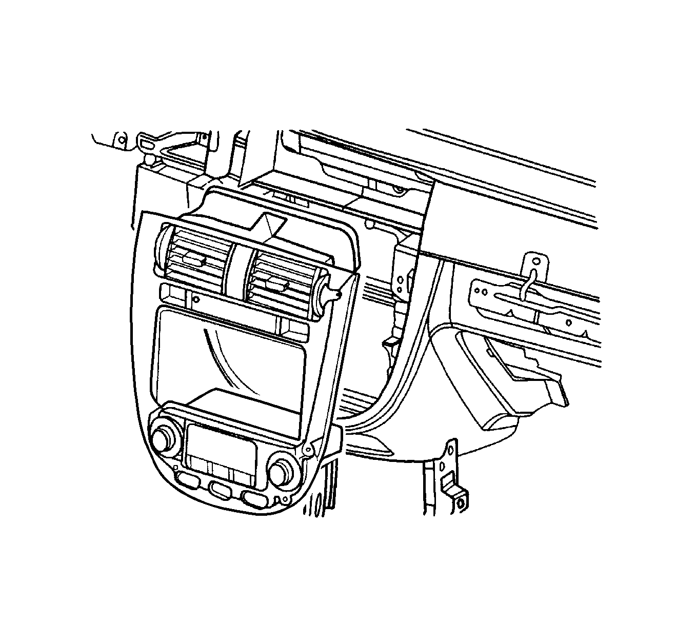
- Remove the center molding.
- Remove the instrument cluster dimmer switch assembly.
- Remove the instrument cluster trim panel. Refer to Instrument Cluster Trim Panel Replacement .
- Remove the instrument cluster. Refer to Instrument Cluster Replacement .
- Remove the glove box and the glove box housing. Refer to Instrument Panel Storage Compartment Replacement .
- Remove the knee bolster. Refer to Knee Bolster Replacement .
- Remove the screws and the instrument panel (I/P) side covers.
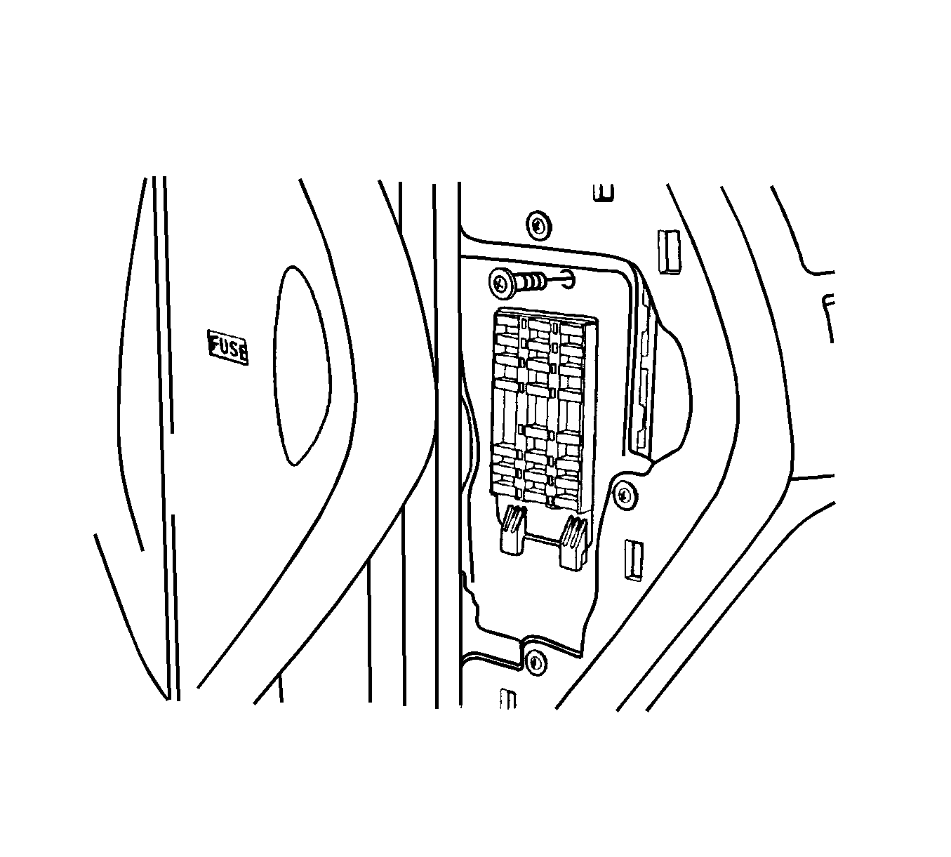
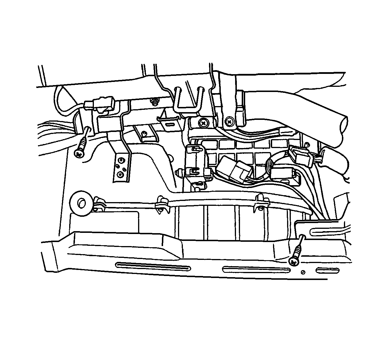
- Remove the screw and the I/P fuse block.
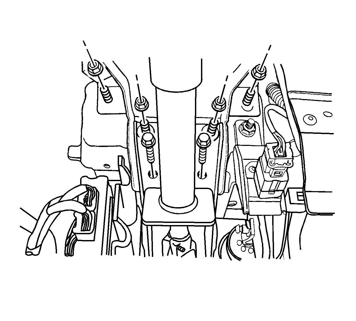
- Remove the nuts and the bolts securing the steering column.
- Disconnect the steering column electrical connector.
- Lower the steering column.
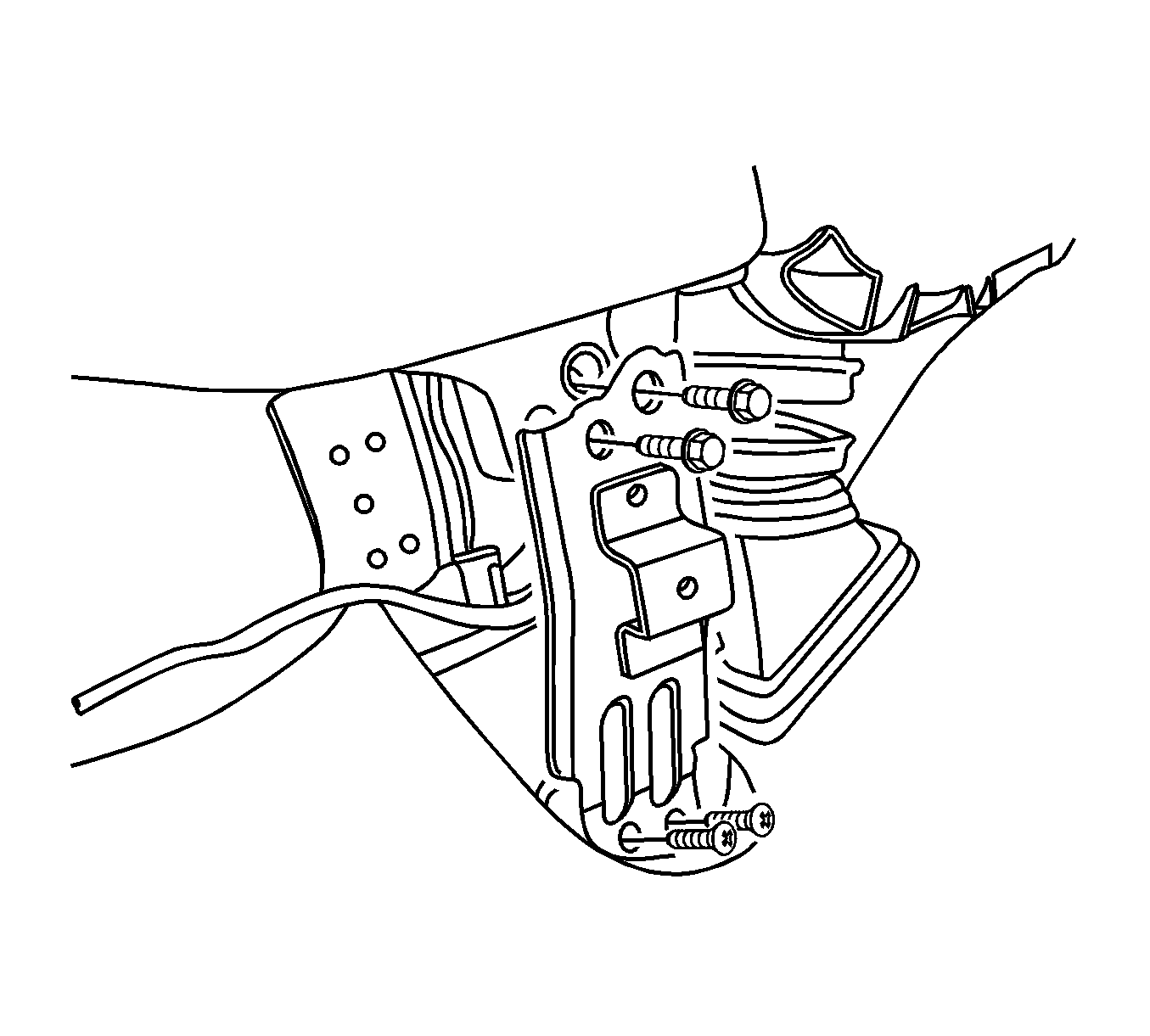
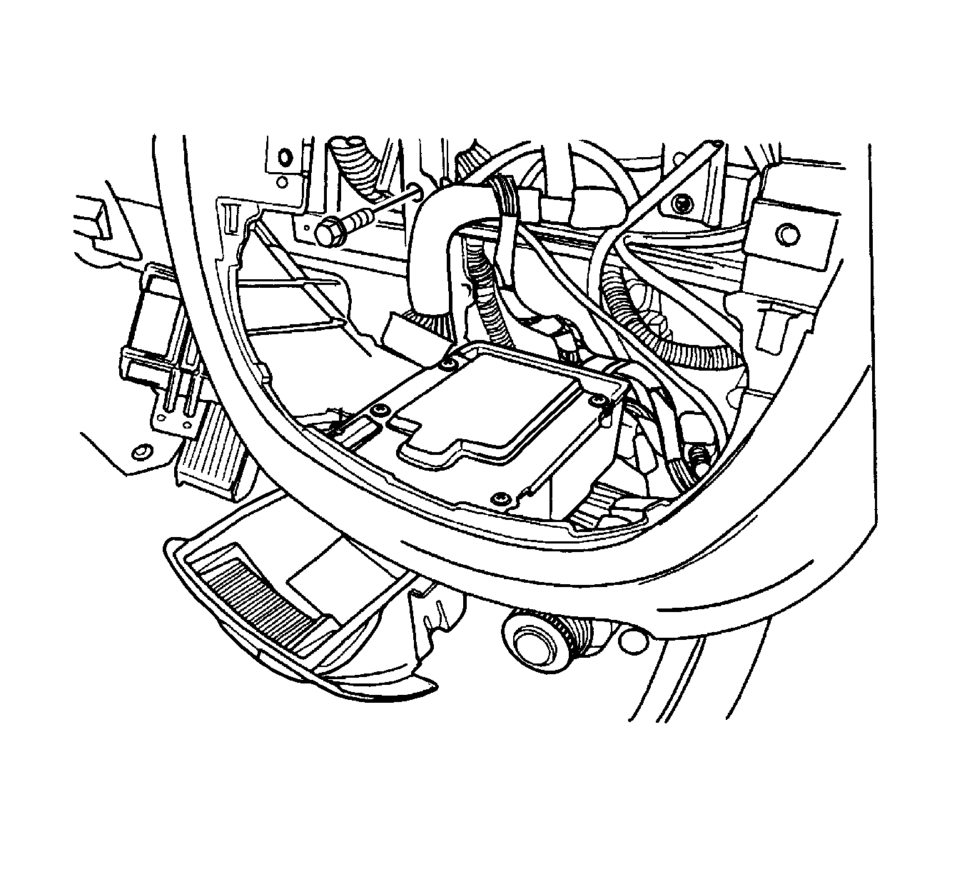
- Remove bolts and screws.
- Remove the connecting pieces.
- Remove the bolt securing the middle of the I/P to the body.
- Remove the I/P screws behind the glove box brace.
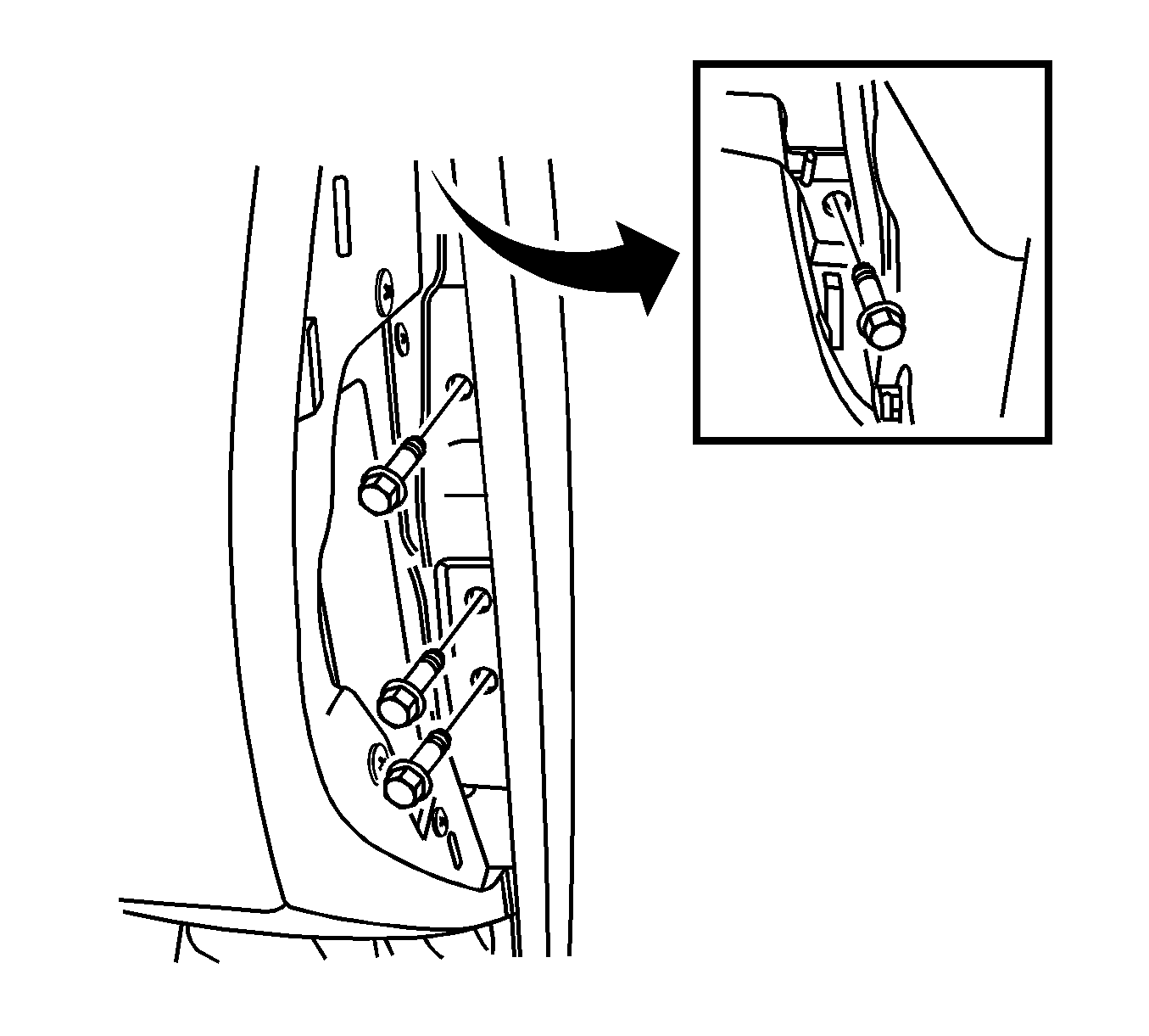
- Remove the bolts securing the sides of the I/P to the body.
- Disconnect the I/P electrical connectors.
- Remove the I/P.
Caution: Refer to Battery Disconnect Caution in the Preface section.
Installation Procedure
- Position the I/P in the vehicle.
- Connect the I/P electrical connectors.
- Install the bolts securing the sides of the I/P to the body.
- Install the I/P screws behind the glove box brace.
- Install the bolt securing the middle of the I/P to the body.
- Install the connecting pieces with bolts and screws.
- Raise the steering column.
- Connect the steering column electrical connector.
- Install the nuts and the bolts securing the steering column.
- Install the I/P fuse block with the screw.
- Install the I/P side covers with the screws.
- Install the knee bolster. Refer to Knee Bolster Replacement .
- Install the glove box and the glove box housing. Refer to Instrument Panel Storage Compartment Replacement .
- Install the instrument cluster. Refer to Instrument Cluster Replacement .
- Install the instrument cluster trim panel. Refer to Instrument Cluster Trim Panel Replacement .
- Install the instrument cluster dimmer switch assembly.
- Install the stereo cassette AM/FM radio. Refer to Radio Replacement.
- Install the center molding.
- Install the sun sensor. Refer to Sun Load Sensor Replacement.
- Install the floor console. Refer to Front Floor Console Replacement .
- Connect the negative battery cable.
Notice: Refer to Fastener Notice in the Preface section.
Tighten
Tighten the I/P-to-body bolts to 22 N·m (16 lb ft).
Tighten
Tighten the I/P-to-body bolts to 22 N·m (16 lb ft).
Tighten
Tighten the connecting pieces bolts to 22 N·m (16 lb ft).
Tighten
| • | Tighten the steering column nuts to 22 N·m (16 lb ft). |
| • | Tighten the steering column bolts to 22 N·m (16 lb ft). |
