Tools Required
| • | DT-47540
(DW340-120-01) Wheel Hub Replacer Adapter |
| • | DT-47541
(DW340-120-02) Wheel Bearing Remover Adapter |
| • | DT-47542
(DW340-120-03) Wheel Bearing Installer Adapter |
| • | DT-47543
(DW-340-120-04) Wheel Bearing Installer Adapter |
Disassembly Procedure
- Raise and support the vehicle. Refer to
Lifting and Jacking the Vehicle.
- Remove the wheel hub, bearing, knuckle, and brake shield as an assembly. Refer to
Steering Knuckle Replacement.
- Use a vise in order to hold the knuckle assembly.
- Remove the brake shield. Refer to
Front Brake Shield Replacement.
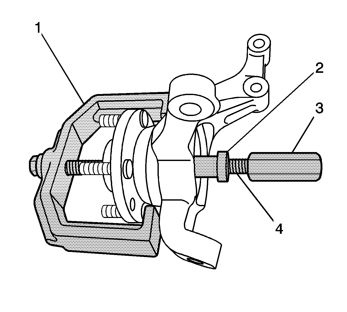
- From the front hub service set
J-37105-C
(
CH-46560
) (DW-340-040), apply
lubricant J-23444-A to the rod (4) J-36661-2 (CH-46560-04).
- Insert the rod J-36661-2 (CH-46560-04) through the following:
| 6.1. | The bearing 217801 (CH-46560-06) (DW340-040-6) |
| 6.2. | The bridge (1) J-37105-1 (CH-46560-01) (DW340-040-1) |
| 6.4. | The adapter (2)
DT-47540
(DW340-120-01) |
- From either the control arm bushing set
J 21474-01
or the front hub service set
CH-46560
, install the nut (3) J-21474-4 (CH-46560-05)
to the rod J-36661-2 (CH-46560-04).
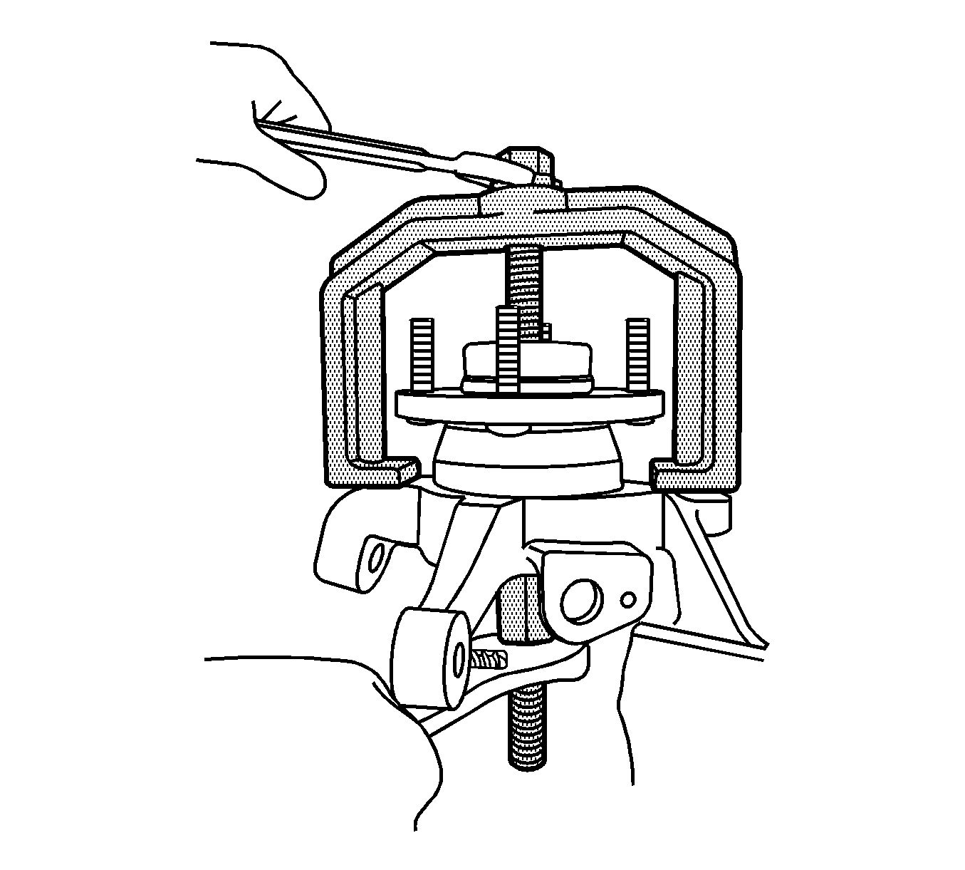
- Remove the wheel hub from the wheel bearing.
- Remove the special tools from the knuckle.
- If necessary, use the split plate
J 22912-B
, or equivalent, and a hydraulic press in order to remove the bearing race from the hub.
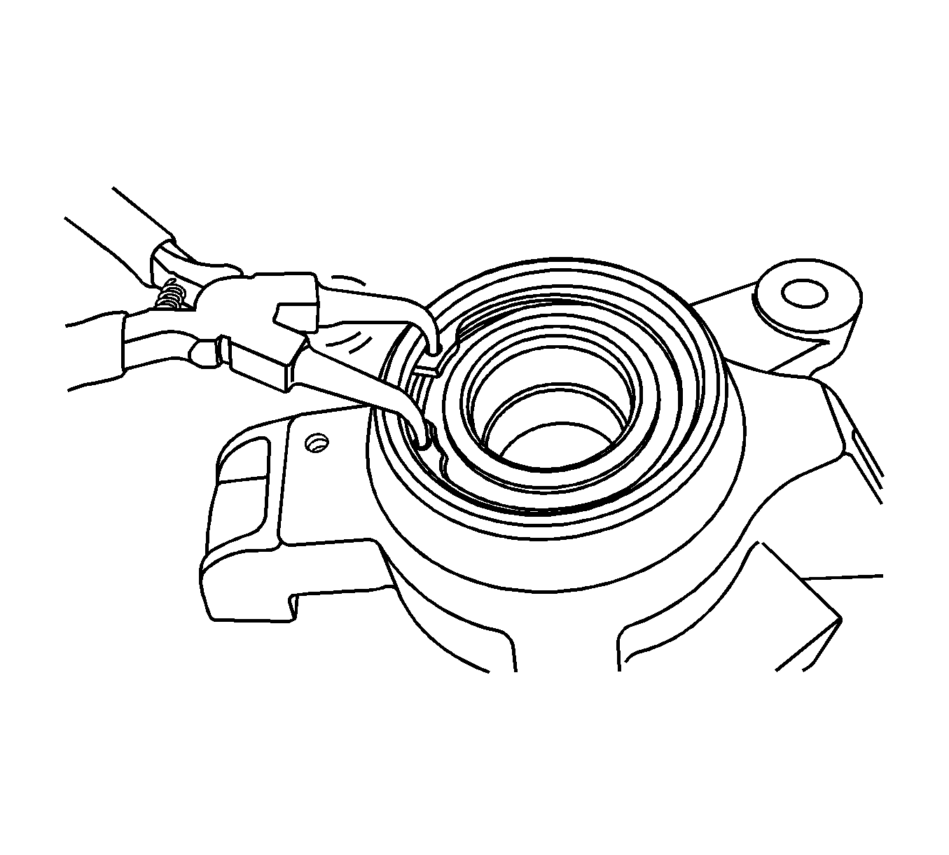
- Remove the retaining ring from the knuckle.
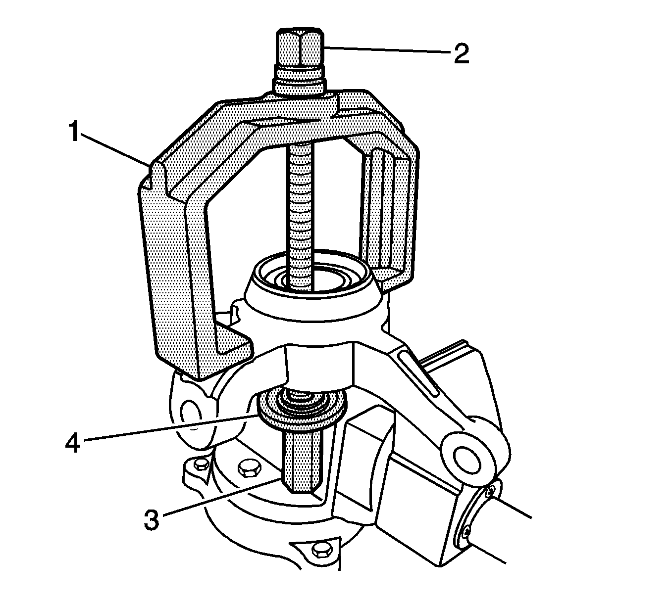
- Insert the rod (2) J-36661-2 (CH-46560-04) through the following:
| 12.1. | The bearing 217801 (CH-46560-06) (DW340-040-6) |
| 12.2. | The bridge (1) J-37105-1 (CH-46560-01) (DW340-040-1) |
| 12.4. | The adapter (4)
DT-47541
(DW340-120-02) |
- Install the nut (3) J-21474-4 (CH-46560-05) to the rod J-36661-2 (CH-46560-04).
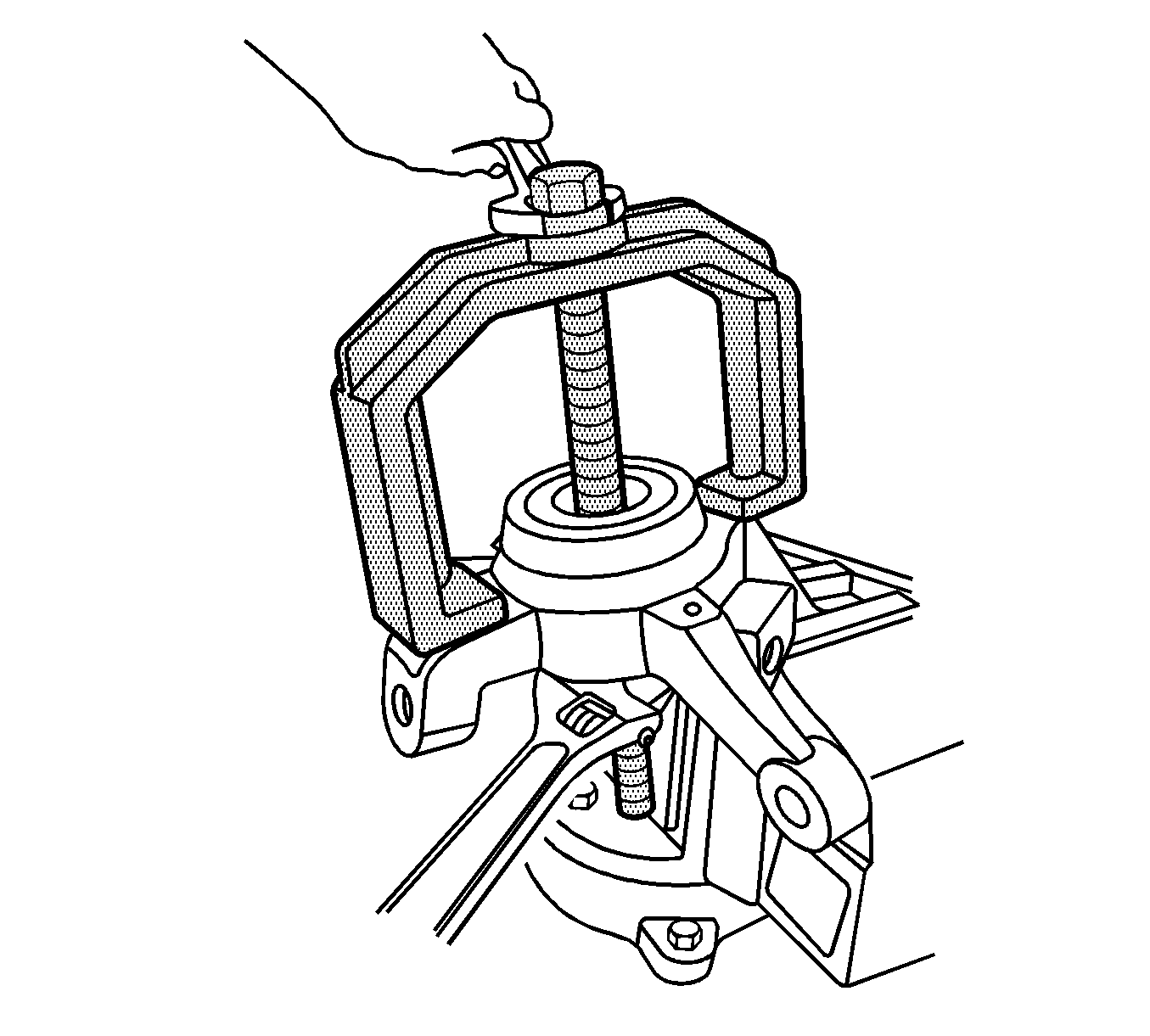
- Remove the wheel bearing from the knuckle.
- Remove the special tools from the knuckle.
- Discard the wheel bearing.
- Clean the bore of the knuckle.
Assembly Procedure
- Use a vise in order to hold the steering knuckle.
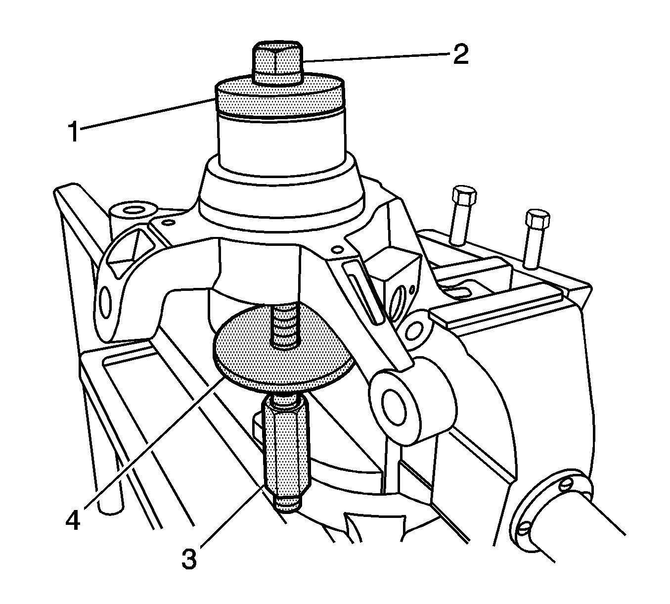
- Insert the rod (2) J-36661-2 (CH-46560-04) through the following:
| 2.1. | The bearing 217801 (CH-46560-06) (DW340-040-6) |
| 2.2. | The adapter (1)
DT-47543
(DW-340-120-04) |
| 2.3. | The NEW wheel bearing |
| 2.4. | The adapter (4)
DT-47542
(DW340-120-03) |
- Install the nut (3) J-21474-4 (CH-46560-05) to the rod J-36661-2 (CH-46560-04).
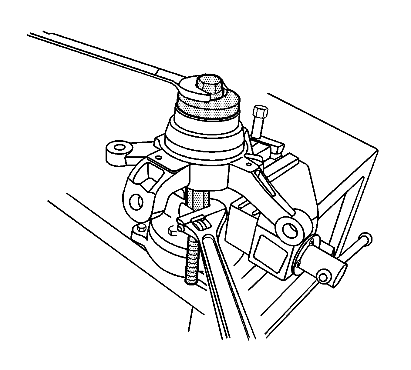
- Install the wheel bearing to the knuckle.
- Remove the special tools from the knuckle.
- Install the retaining ring to the knuckle.
- Install the brake shield. Refer to
Front Brake Shield Replacement.
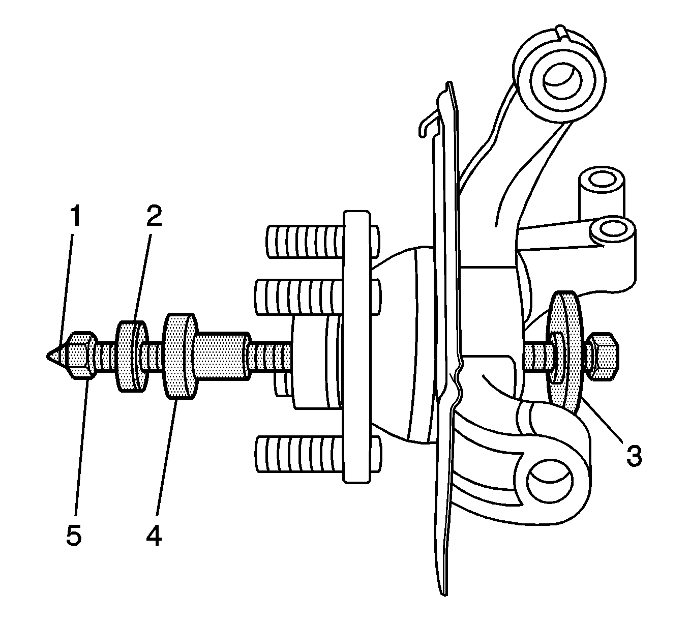
- Insert the rod (1) J-36661-2 (CH-46560-04) through the following:
| 8.1. | The adapter (3)
DT-47541
(DW340-120-02) |
| 8.3. | The adapter (4)
DT-47540
(DW340-120-01) |
| 8.4. | The bearing (2) 217801 (CH-46560-06) (DW340-040-6) |
- Install the nut (5) to the rod J-36661-2 (CH-46560-04).
- Install the hub to the wheel bearing.
- Remove the special tools from the knuckle.
- Verify the hub rotates smoothly.
- Install the wheel hub, bearing, knuckle, and brake shield as an assembly. Refer to
Steering Knuckle Replacement.
- Lower the vehicle.


