For 1990-2009 cars only
Removal Procedure
- Raise and support the vehicle. Refer to Lifting and Jacking the Vehicle in General Information.
- Remove the rear tires and the wheels. Refer to Tire and Wheel Removal and Installation in Tires and Wheels.
- Inspect the rear ball joints. Refer to Ball Joint Inspection in Suspension General Diagnosis.
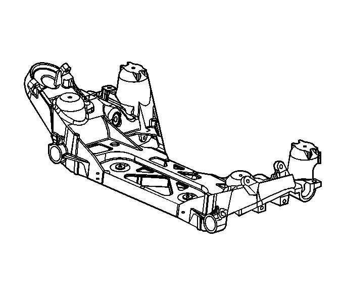
- Support rear differential carrier using a utility stand.
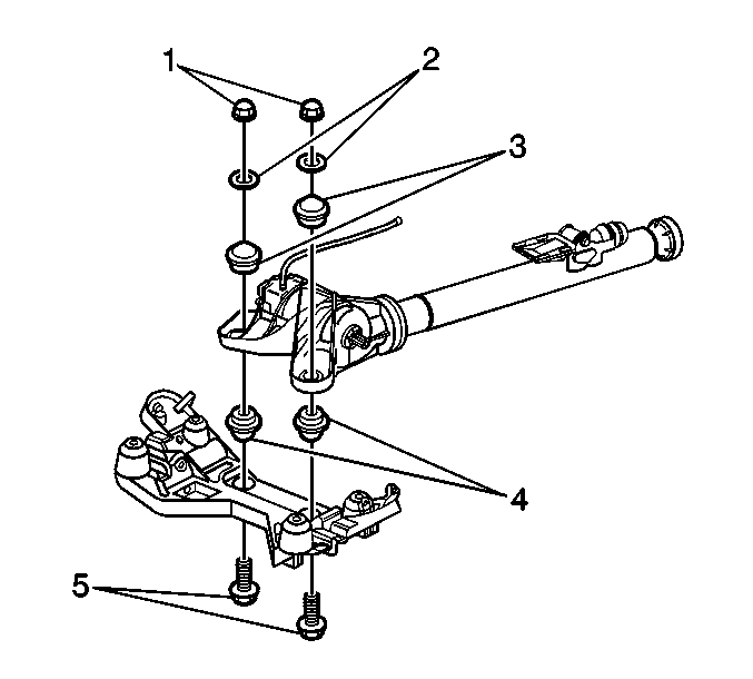
- Remove the rear differential carrier mounting bolts (5) from the rear crossmember. Refer to Differential Replacement in Rear Drive Axle.
- Remove the rear suspension knuckle. Refer to Knuckle Replacement in Rear Suspension.
- Disconnect the wheel speed sensor harness from the lower control arm and from the rear cross member.
- Remove the rivets that attach the park brake cable to the rear crossmember.
- Remove the automatic level control (ALC) height sensor and link from the crossmember bar and lower control arm. Refer to Automatic Level Control Sensor Replacement in Automatic Level Control.
- Secure the ALC wiring harness out of the way.
- Using a utility jack, support the rear crossmember.
- Remove the rear crossmember mounting bolts.
- Lower the rear crossmember.
- Remove the rear stabilizer shaft. Refer to Stabilizer Shaft Replacement in Rear Suspension.
- Remove the rear axle upper control arms from the rear crossmember. Refer to Rear Axle Upper Control Arm Replacement in Rear Suspension.
- Remove the rear axle lower control arms from the rear crossmember. Refer to Rear Axle Lower Control Arm Replacement in Rear Suspension.
- Remove the tie rods from the rear crossmember. Refer to Tie Rod Replacement in Rear Suspension.
Installation Procedure
- Install the tie rods to the crossmember. Refer to Tie Rod Replacement in Rear Suspension.
- Install the rear axle lower control arms onto the rear crossmember. Refer to Rear Axle Lower Control Arm Replacement in Rear Suspension.
- Install the rear axle upper control arms onto the rear crossmember. Refer to Rear Axle Upper Control Arm Replacement in Rear Suspension.
- Install the rear stabilizer shaft onto the rear crossmember. Refer to Stabilizer Shaft Replacement in Rear Suspension.
- Raise the rear crossmember.
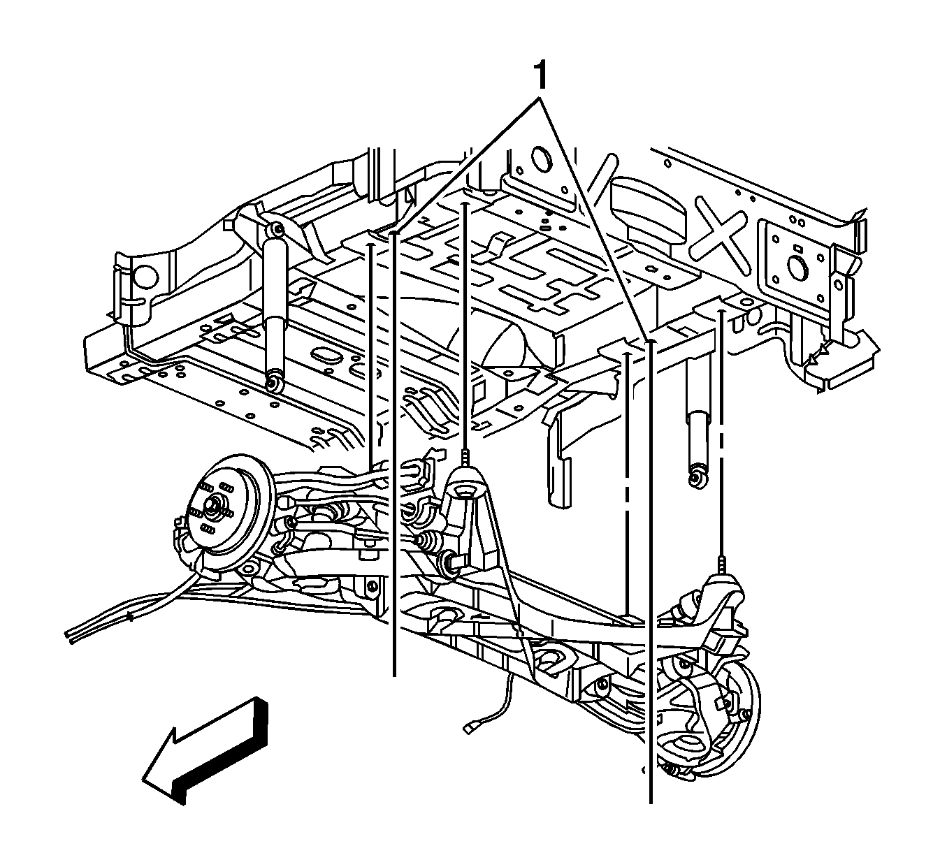
- Align the rear crossmember using guide pins through the rail holes (1).
- Install the rear crossmember mounting bolts.
- Tighten the mounting bolts.
- Install the ALC height sensor onto the crossmember and lower control arm. Refer to Automatic Level Control Sensor Replacement in Automatic Level Control.
- Install the rear differential carrier mounting bolts (5). Refer to Differential Replacement in Rear Drive Axle.
- Attach the parking brake cable onto the rear crossmember. Refer to Parking Brake Rear Cable Replacement - Left Side and Parking Brake Rear Cable Replacement - Right Side in Park Brake.
- Connect the wheel speed sensor harness onto the rear crossmember and the lower control arm.
- Install the rear suspension knuckle. Refer to Knuckle Replacement in Rear Suspension.
- Install the rear tires and the wheels. Refer to Tire and Wheel Removal and Installation in Tires and Wheels.
- Lower the vehicle.
- Inspect for rear wheel alignment and adjust as necessary. Refer to Wheel Alignment Measurement in Wheel Alignment.
Notice: Refer to Fastener Notice in the Preface section.
Tighten
Tighten the rear crossmember mounting bolts to 130 N·m (96 lb ft) .
