For 1990-2009 cars only
Removal Procedure
- Disconnect the battery negative cable. Refer to Battery Negative Cable Disconnection and Connection.
- Remove the air cleaner assembly. Refer to Air Cleaner Assembly Replacement.
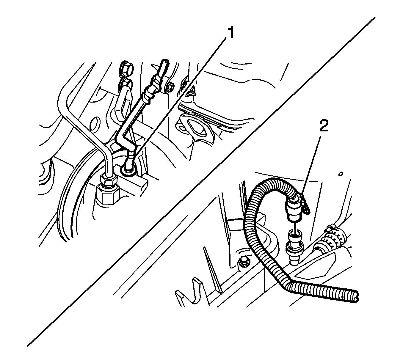
- Disconnect the power steering oil pressure switch connector (1) and the air conditioner pressure sensor connector (2).
- Disconnect the brake vacuum hose.
- Disconnect the PCV breather hose.
- Disconnect the intake temperature/pressure sensor connector.
- Disconnect the accelerator cable.
- Disconnect the canister hose from the intake manifold.
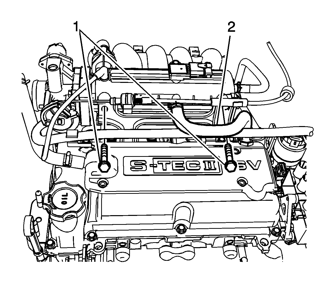
- Remove intake manifold front bracket upper retaining bolts (1).
- Remove the fuel rail.
- Remove the EGR pipe.
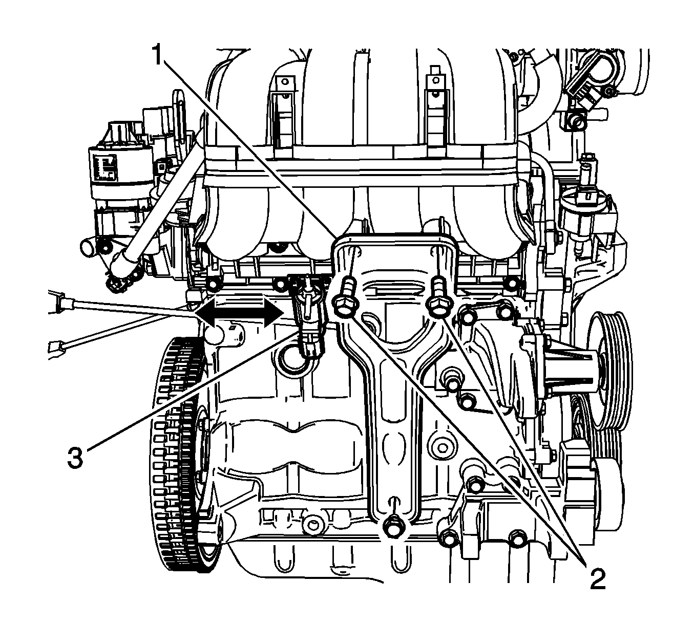
- Disconnect the VGIS solenoid valve (3).
- Remove the intake manifold rear bracket bolts (2).
- Remove the intake manifold rear bracket (1).
- Remove the engine wiring harness from the intake manifold.
- Remove the intake manifold (1).
- Remove the intake manifold gasket.
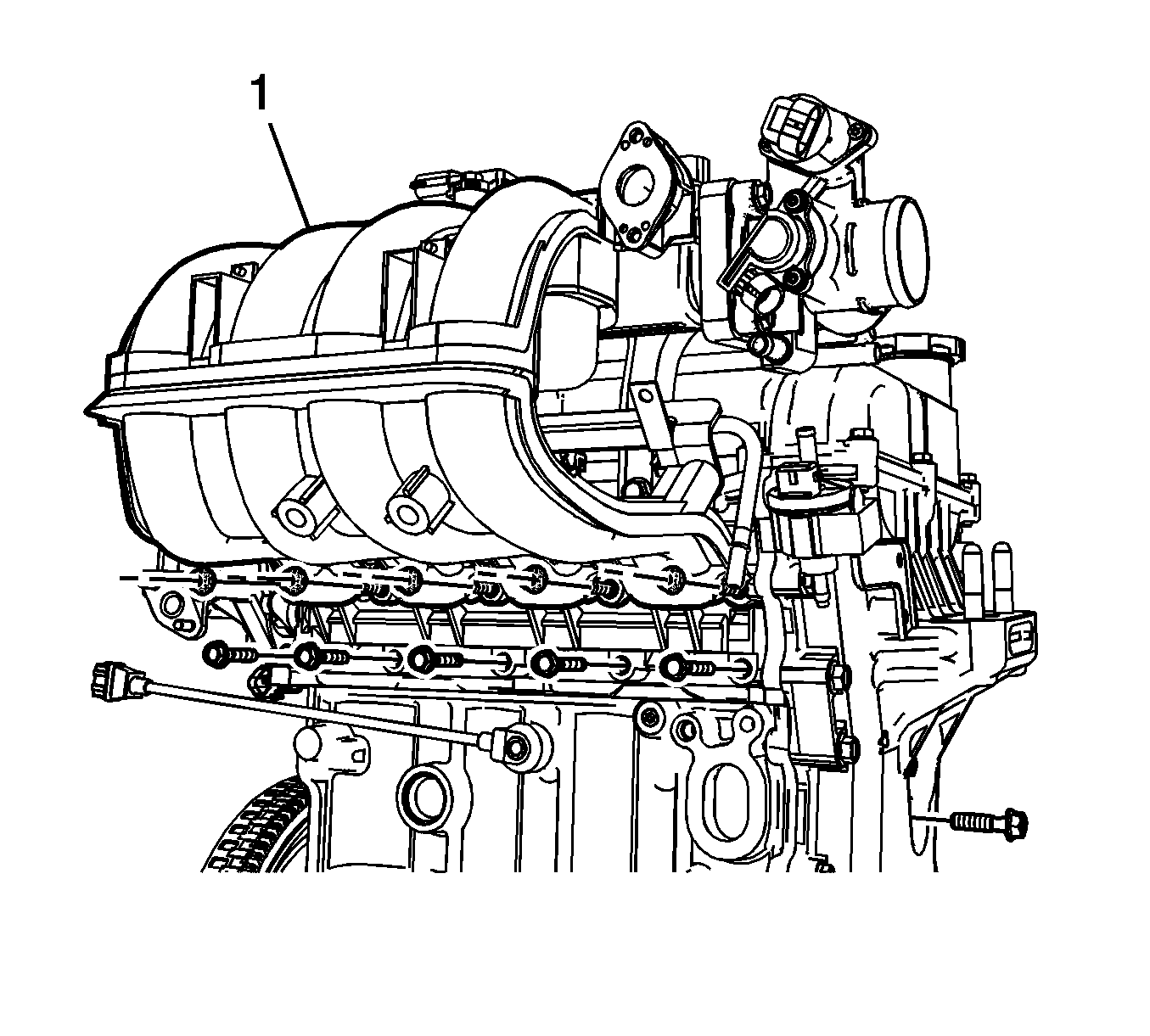
Installation Procedure
- Install the intake manifold (1) with the new gasket.
- Install the intake manifold bolts.
- Install the intake manifold rear bracket (1).
- Install the intake manifold rear bracket retaining bolts (2).
- Install the EGR pipe.
- Install the fuel rail. Refer to Fuel Injection Fuel Rail Assembly Replacement.
- Install the intake manifold front bracket upper retaining bolts (1).
- Connect the brake vacuum hose.
- Connect the PCV breather hose.
- Connect the intake temperature/pressure sensor connector.
- Connect the accelerator cable.
- Connect the canister hose from the intake manifold.
- Connect the power steering oil pressure switch connector (1) and the air conditioner pressure sensor connector (2).
- Install the air cleaner assembly. Refer to Air Cleaner Assembly Replacement.
- Connect the battery negative cable. Refer to Battery Negative Cable Disconnection and Connection.

Caution: Refer to Fastener Caution in the Preface section.
Tighten
Tighten the intake manifold retaining bolts to 10 N·m (7.4 lb ft).

Tighten
| • | Tighten the bracket upper bolts to 25 N·m (18.4 lb ft). |
| • | Tighten the bracket lower bolts to 50 N·m (36.8 lb ft). |


Tighten
Tighten the intake manifold support bracket upper bolts to 2 N·m (1.5 lb ft).

