For 1990-2009 cars only
Removal Procedure
- Disconnect the negative battery cable. Refer to Battery Negative Cable Disconnection and Connection.
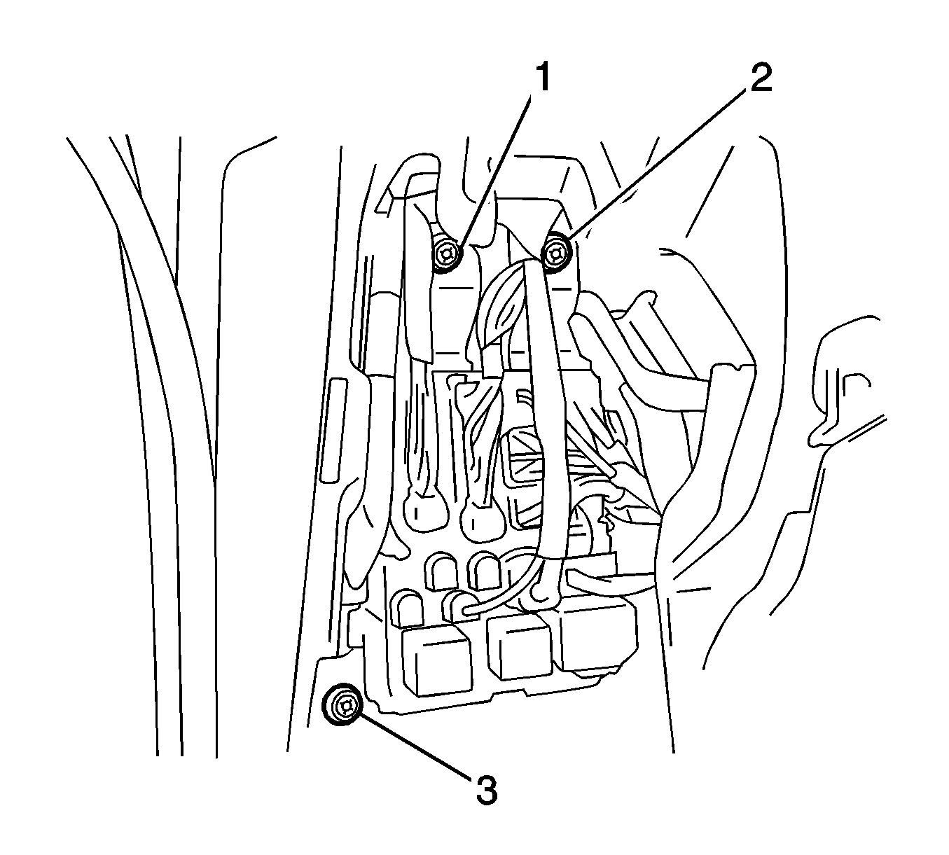
- Remove the bolts (1-3) and separate the main body ECU.
- Disconnect the clutch pedal switch connector.
- Disconnect the clutch switch connector.
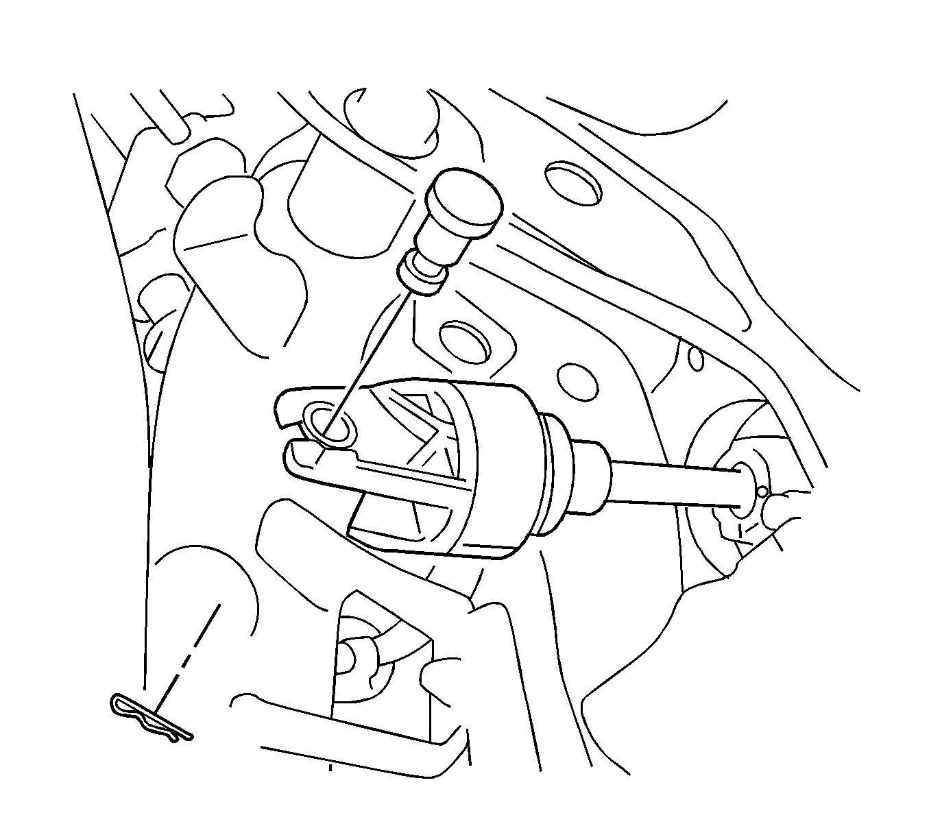
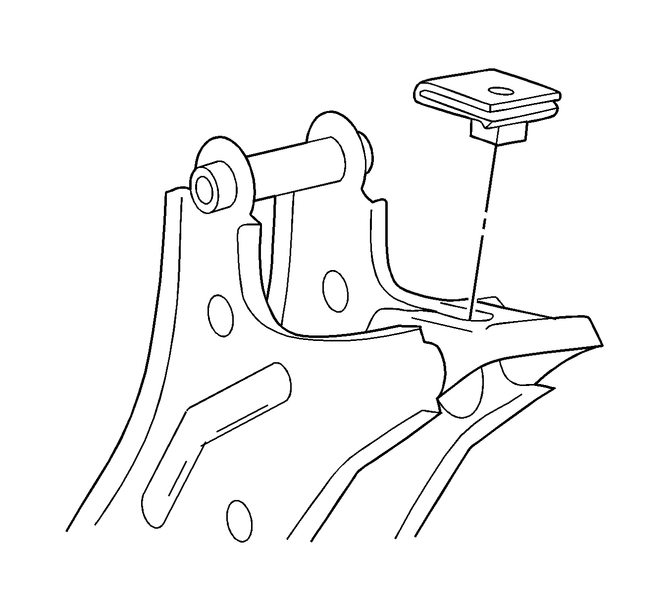
- Remove the clip and hole pin.
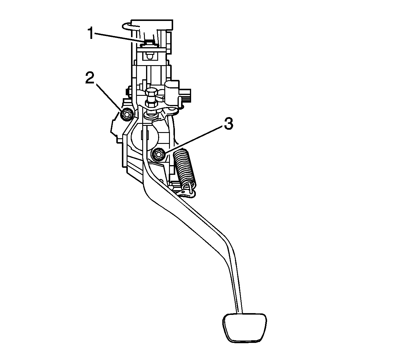
- Remove the nuts (2,3), bolt (1) and clutch pedal support sub-assembly.
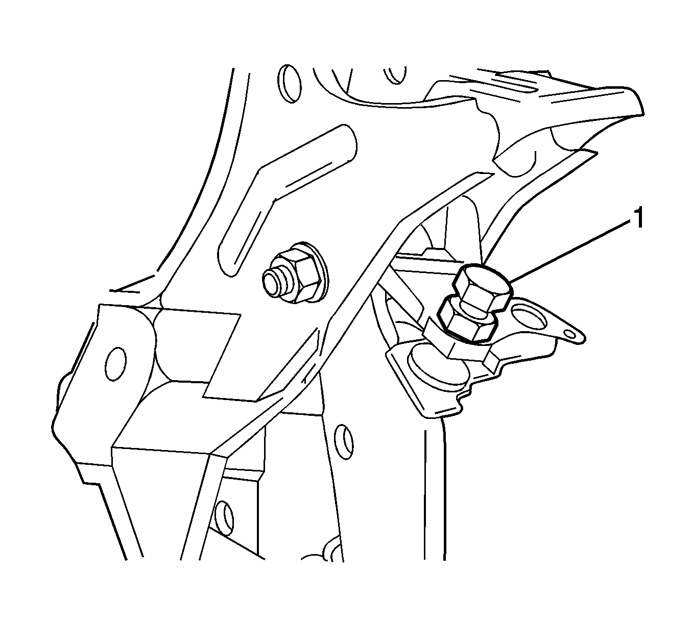
- Remove the nut from the clutch pedal support sub-assembly.
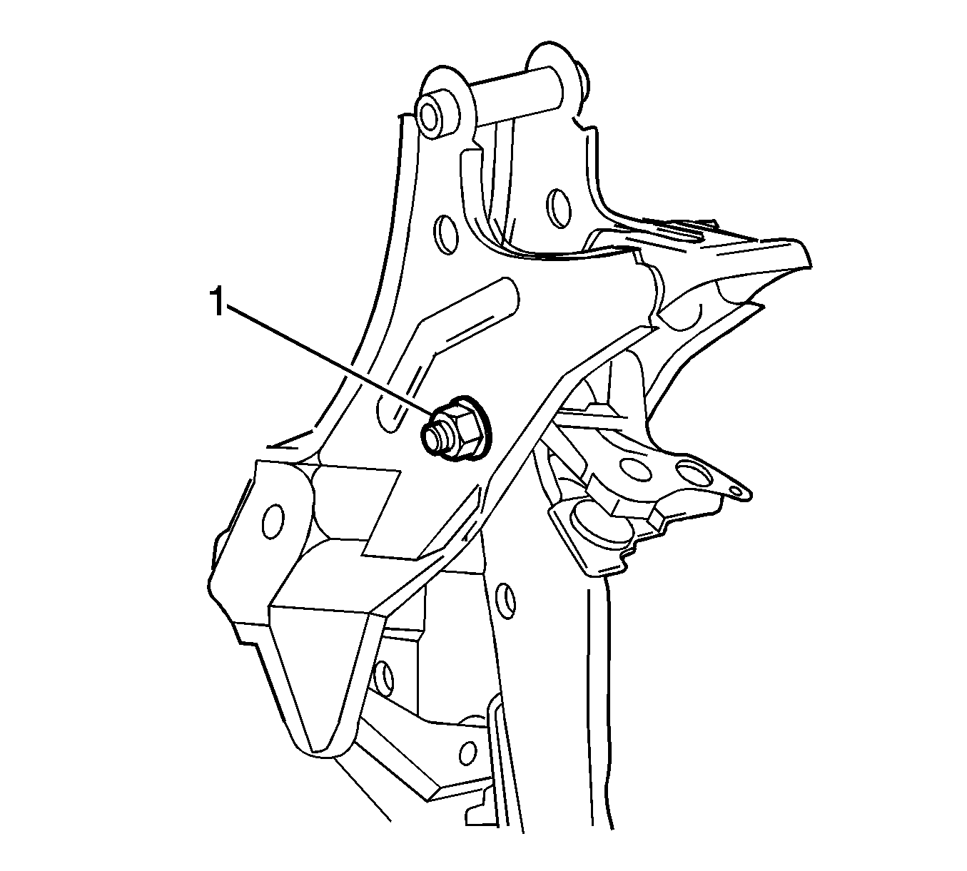
- Remove the clutch pedal stopper bolt (1) from the clutch pedal support sub-assembly.
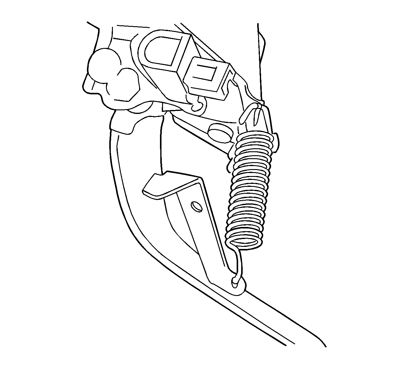
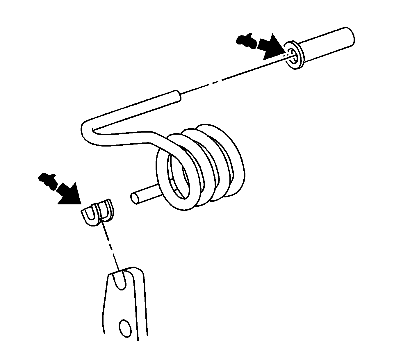
- Remove the clutch pedal spring.
- Mount the clutch pedal in a soft jaw vise.
- While the clutch pedal is fully depressed, remove the turnover spring.
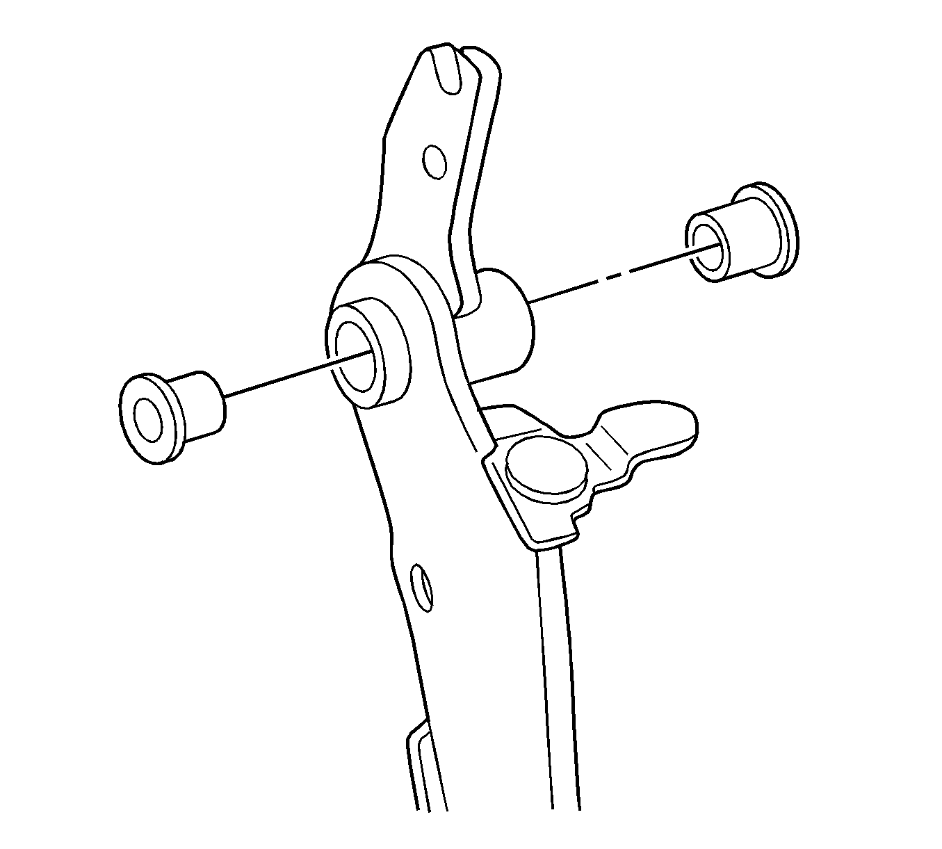
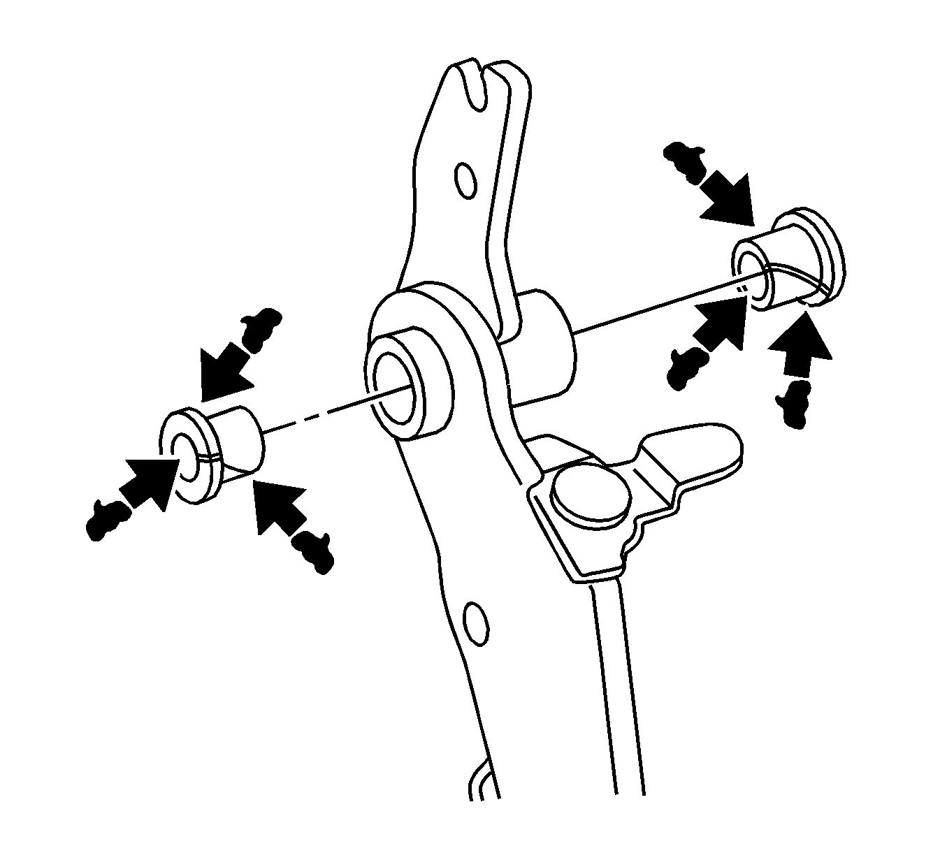
- Remove the turnover bushings from the clutch pedal sub-assembly and clutch pedal support sub-assembly.
- Remove the bolt, nut (1) and clutch pedal sub-assembly from the clutch pedal support sub-assembly.
- Remove the clutch pedal pad from the clutch pedal sub-assembly.
- Remove the bushings from the clutch pedal sub-assembly.
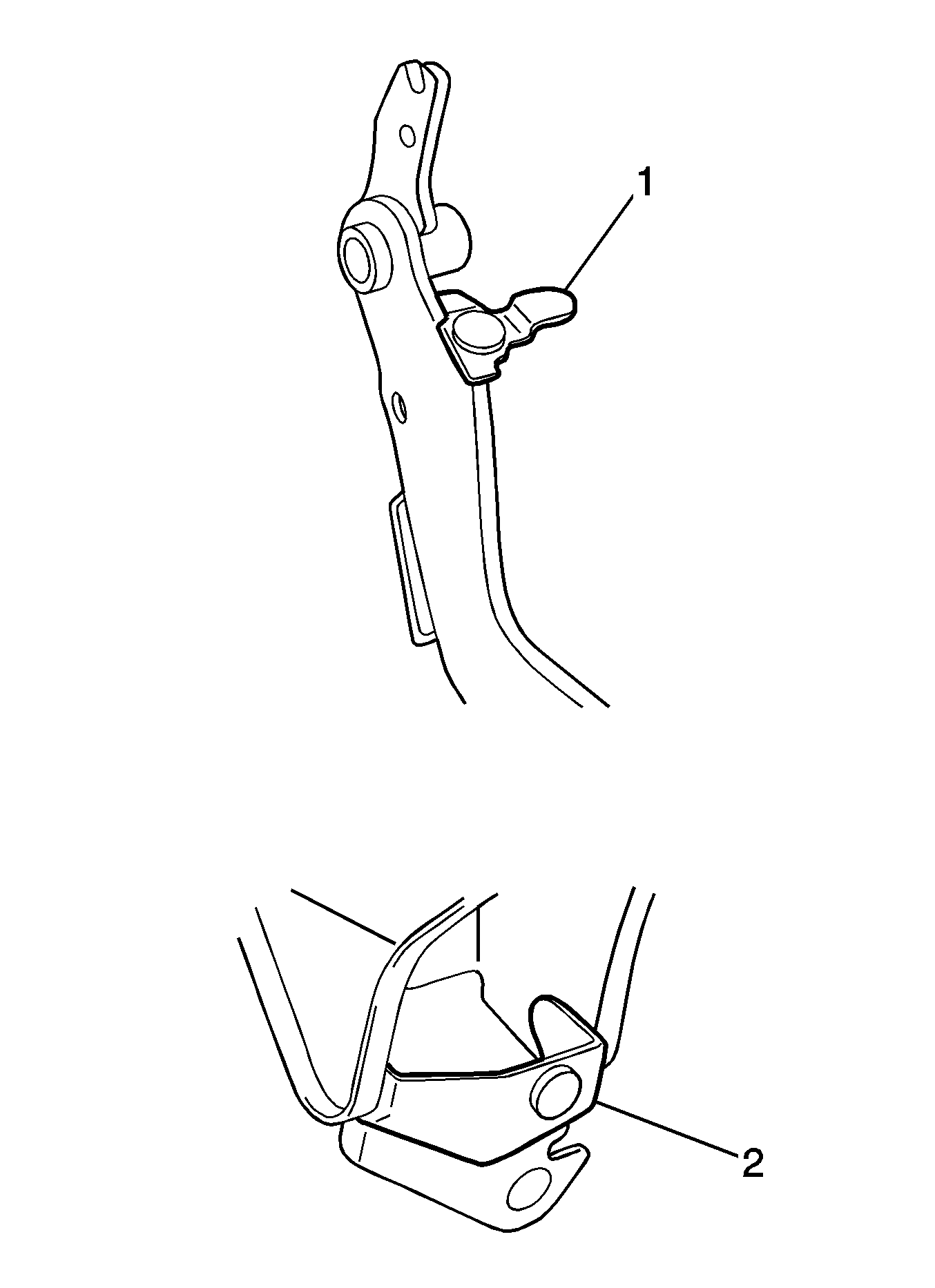
- Remove the No. 1 clutch pedal cushions (1) from the clutch pedal sub-assembly and clutch pedal support sub-assembly.
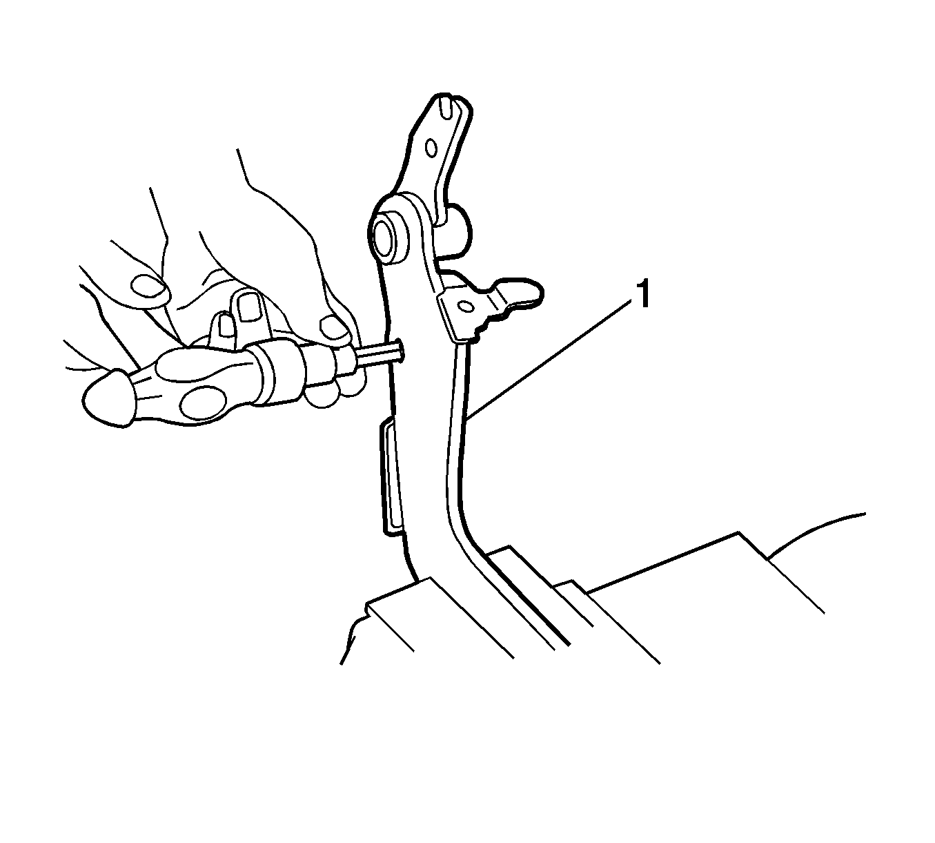
- Using an 8 mm hexagon wrench and a hammer, remove the clevis bushing from the clutch pedal sub-assembly (1).
- Remove the nut and cruise control clutch switch assembly from the clutch pedal support assembly.
- Remove the nut and clutch pedal position switch assembly from the clutch pedal support assembly.
Inspection Procedure
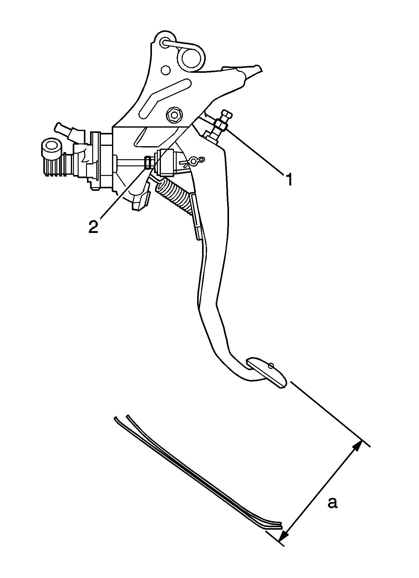
- Turn back the floor carpet.
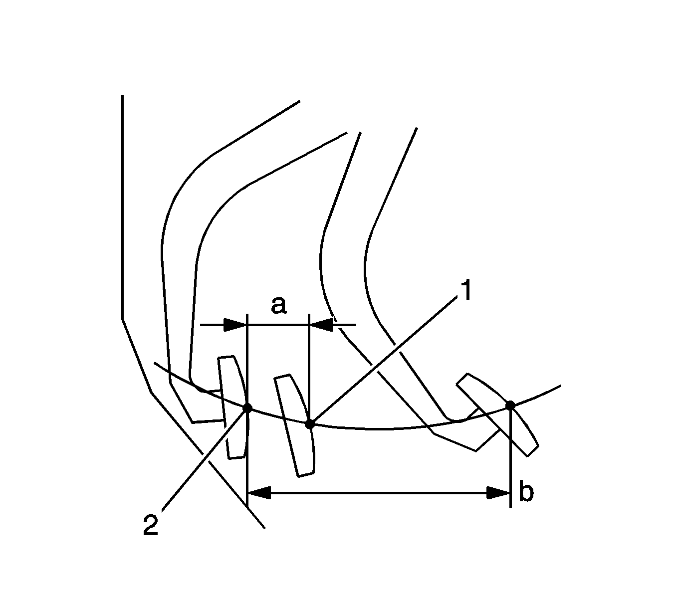
- Check that the pedal height is correct (a.
- Loosen the lock nut and turn the stopper bolt (1) until the correct height is obtained.
- Install the lock nut and tighten to 25 N·m (18 lb ft).
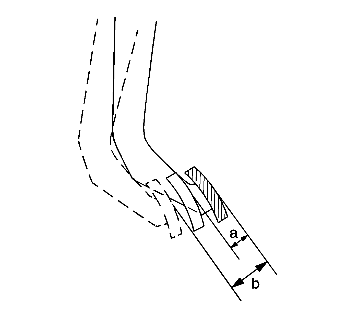
- Check that pedal free play and push rod play are correct (a, b).
- Depress the pedal until clutch resistance begins to be felt.
- Gently depress the pedal until resistance begins to increase a little.
- If necessary, adjust the pedal free play and push rod play.
- Loosen the lock nut and turn the push rod until the correct free play and push rod play are obtained.
- Tighten the lock nut to 12 N·m (106 lb in).
- After adjusting the pedal free play, check the pedal height.
- Check the clutch release point.
- Pull the parking brake lever and install wheel chocks.
- Start the engine and run it at idle.
- Without depressing the clutch pedal, slowly move the shift lever into reverse until the gears contact.
- Gradually depress the clutch pedal and measure the stroke distance from the point that the gear noise stops, release point, up to the full stroke end position (a).
- If the distance is not as specified, perform the following procedure:
Caution: Refer to Fastener Caution in the Preface section.
Specification
Pedal free play: 5.0 to 15.0 mm (0.197 to 0.591 in)
Specification
Push rod play at pedal top: 1.0 to 5.0 mm (0.039 to 0.197 in)
Specification
Standard distance: 25 mm (0.98 in) or more (from pedal stroke end position (2) to release point)
| • | Check the pedal height. |
| • | Check the push rod play and pedal free play. |
| • | Bleed the clutch line. |
| • | Check the clutch cover and disc. |
Engine Type | Pedal Height: mm (in) |
|---|---|
2.4L LAX | 166.4 to 176.4 (6.551 to 6.945) |
1.8L LAY | 157.7 to 167.7 (6.209 to 6.602) |
Installation Procedure
- Install the clutch pedal position switch assembly to the clutch pedal support sub-assembly with the nut and tighten to 16 N·m (12 lb ft).
- Install the cruise control clutch switch assembly to the clutch pedal support sub-assembly with the nut and tighten to 16 N·m (12 lb ft).
- Apply MP grease to the inside of a new clevis bushing.
- Install the clevis bushing to the clutch pedal sub-assembly.
- Install the No. 1 clutch pedal cushions (1, 2) to the clutch pedal sub-assembly and clutch pedal support sub-assembly.
- Apply MP grease to both sides and end surface of the new bushings.
- Install the bushings to the clutch pedal.
- Install the clutch pedal pad to the clutch pedal sub-assembly.
- Install the clutch pedal sub-assembly to the clutch pedal support sub-assembly with the bolt and nut (1) and tighten to 37 N·m (27 lb ft).
- Apply MP grease to the sliding portion of the turnover bushings.
- Install new turnover bushings to the clutch pedal sub-assembly and clutch pedal support sub-assembly.
- Install the turnover spring.
- Install the clutch pedal spring.
- Install the clutch pedal stopper bolt (1) so that its end touches the clutch pedal cushion.
- Install the nut to the clutch pedal support sub-assembly.
- Install the clutch pedal support sub-assembly with the nuts (2, 3) and bolts (1) and tighten.
- Connect the clevis to the clutch pedal sub-assembly with the hole pin.
- Install the clip to the hole pin.
- Connect the clutch pedal switch connector.
- Connect the clutch switch assembly connector.
- Install the main body ECU with the bolts (1-3).
- Connect the negative battery cable. Refer to Battery Negative Cable Disconnection and Connection.
Caution: Refer to Fastener Caution in the Preface section.
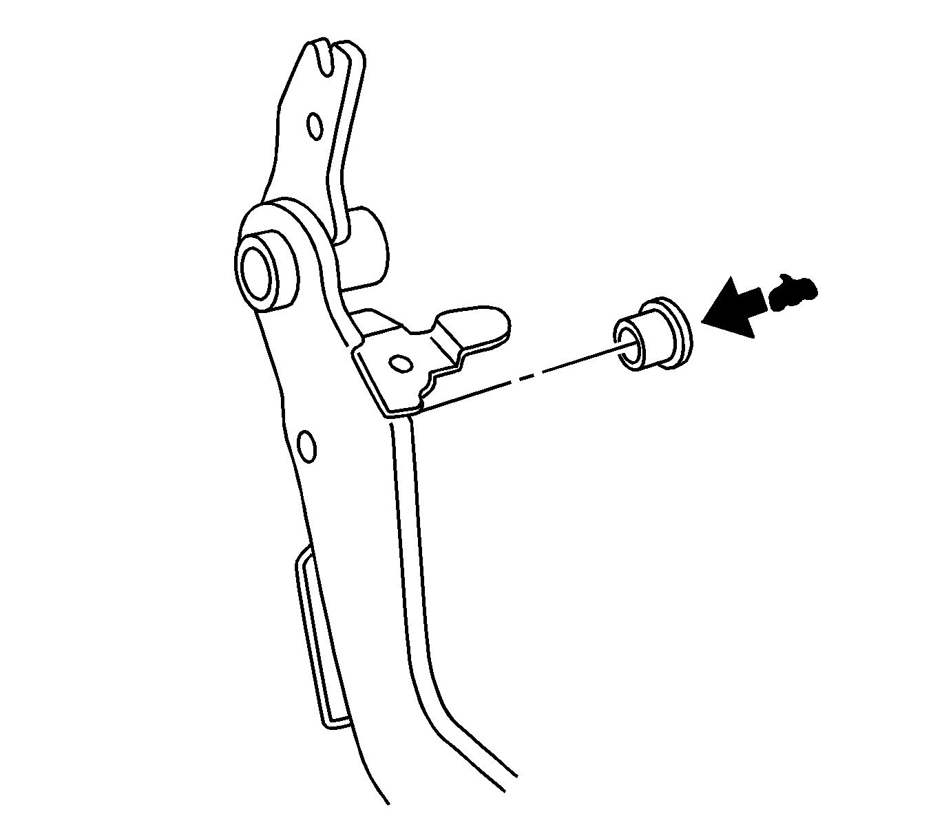
Note: Install the clevis bushing from the right side of the vehicle.
Note: Install the bolt from the right side of the vehicle.
| • | The bolts to 24 N·m (17 lb ft). |
| • | The nuts to 13 N·m (115 lb in). |
Note: Install the hole pin from the right side of the vehicle.
