Removal Procedure
- Raise and support the vehicle. Refer to Lifting and Jacking the Vehicle.
- Remove the tire and wheel assembly from the vehicle. Refer to Tire and Wheel Removal and Installation.
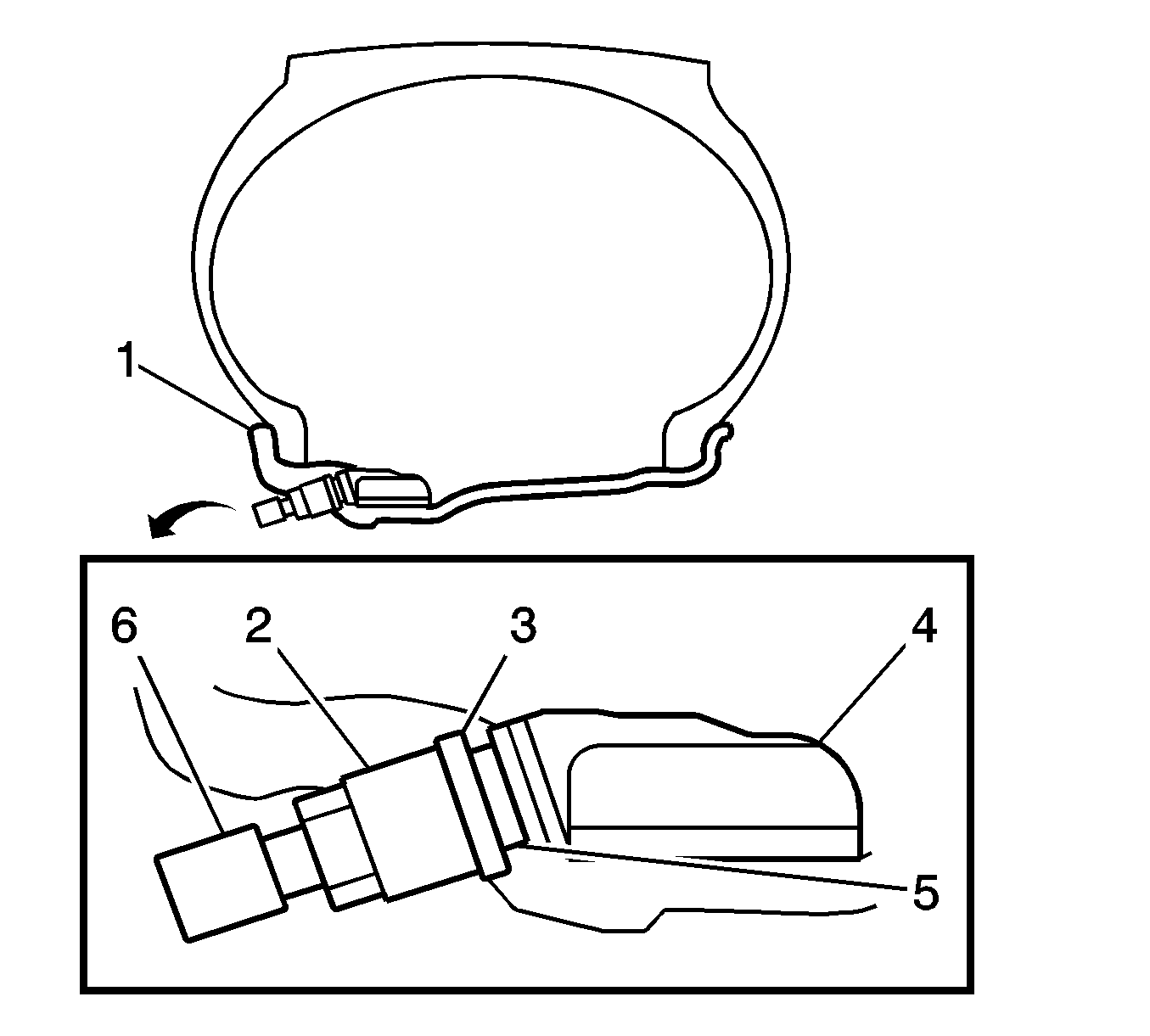
- Remove the valve stem cap (6).
- Remove the valve core from the valve stem.
- Deflate the tire completely.
- Use paint in order to place a match mark on the tire near the valve stem.
- Remove the nut (2) from the valve stem.
- Remove the washer (3).
- Push the valve stem and the tire pressure indicator sensor into the tire.
- Place the tire and wheel assembly in a European-type rim clamp tire changing machine.
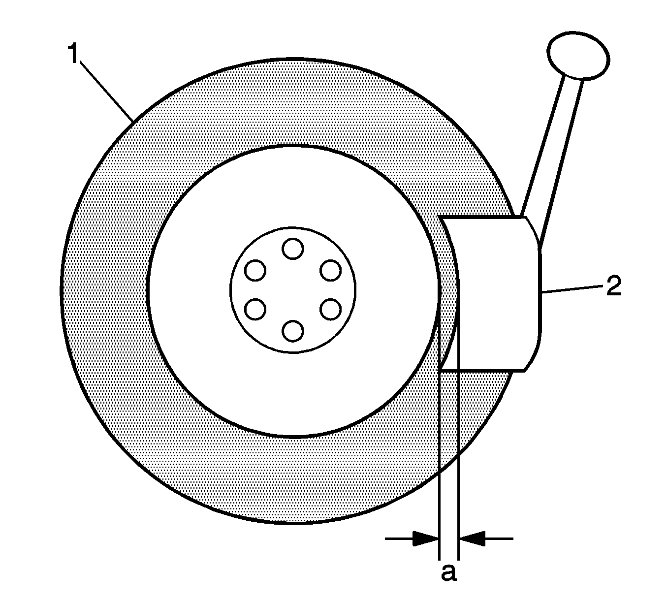
- Position the bead breaking fixture head (2) 90, 180, and 270 degrees from the valve stem.
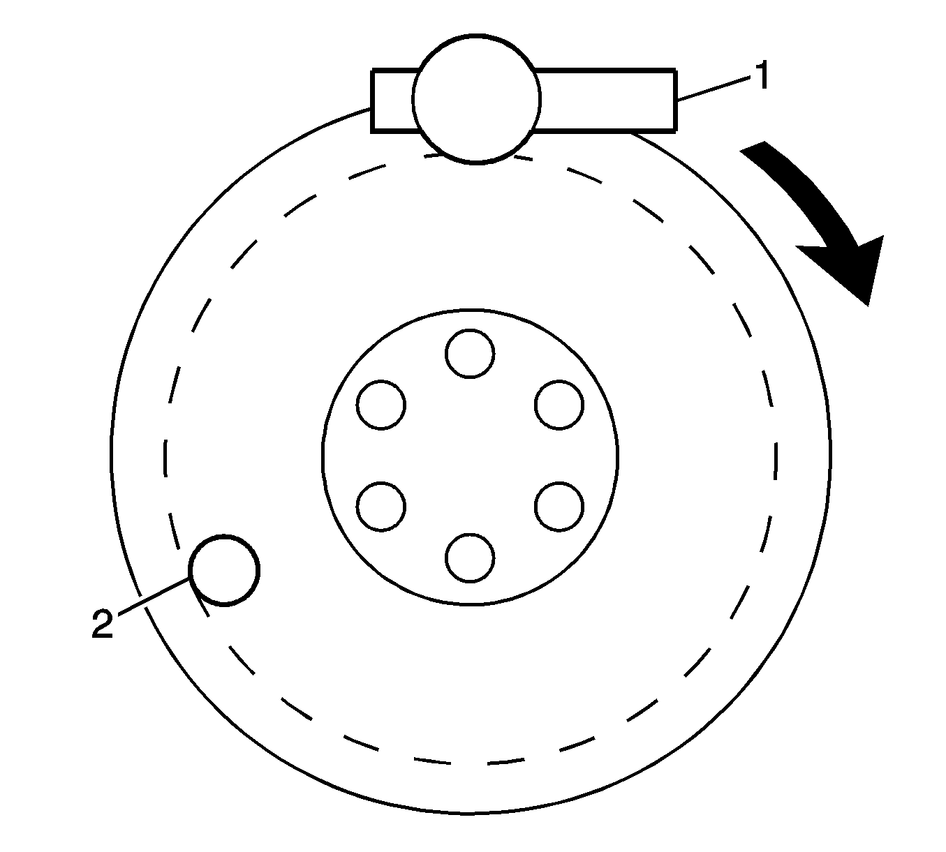
- Position the tire and wheel assembly on the tire changing machine with the valve stem at the 2 o'clock position and the head at the 12 o'clock position.
- Insert the tire iron pry bar.
- Rotate the wheel clockwise and pry the top bead up over the wheel rim.
- Remove the tire pressure indicator sensor. Refer to Tire Pressure Indicator Sensor Replacement.
- Position the tire and the wheel with the valve stem at the 2 o'clock position and the head at the 12 o'clock position.
- Insert the tire iron pry bar.
- Rotate the wheel clockwise and pry the bottom bead up over the wheel rim. Remove the tire from the wheel.
- Use a wire brush or coarse steel wool in order to remove any rubber, light rust, or corrosion from the wheel bead seats.
- Remove any tire sealant or foreign matter from the sensor components.
- Inspect the sensor for deformation, damage, or other concerns. If you are replacing the sensor, also replace the old grommet, washer, and nut.
- Remove any tire sealant or foreign matter from the wheel.
Caution: Use a tire changing machine in order to dismount tires. Do not use hand tools or tire irons alone in order to remove the tire from the wheel. Damage to the tire beads or the wheel rim could result.
Caution: Do not scratch or damage the clear coating on aluminum wheels with the tire changing equipment. Scratching the clear coating could cause the aluminum wheel to corrode and the clear coating to peel from the wheel.
Caution: Damage to either the tire bead or the wheel mounting holes can result from the use of improper wheel attachment or tire mounting procedures. It takes up to 70 seconds for all of the air to completely exhaust from a large tire. Failure to follow the proper procedures could cause the tire changer to put enough force on the tire to bend the wheel at the mounting surface. Such damage may result in vibration and/or shimmy, and under severe usage lead to wheel cracking.
Specification
The distance (a) between the head and the wheel is 10-20 mm (0.39-0.79 in).
Note: Ensure there is no oil, water, or lubricant on any sensor components.
Note: Ensure there is no oil, water, or lubricant around the rim hole.
Installation Procedure
- Install the tire pressure indicator sensor. Refer to Tire Pressure Indicator Sensor Replacement.
- Apply GM Goodwrench Rubber Lubricant, GM P/N 12345884 (Canadian P/N 5728223), or equivalent, to the tire beads and to the wheel bead seats.
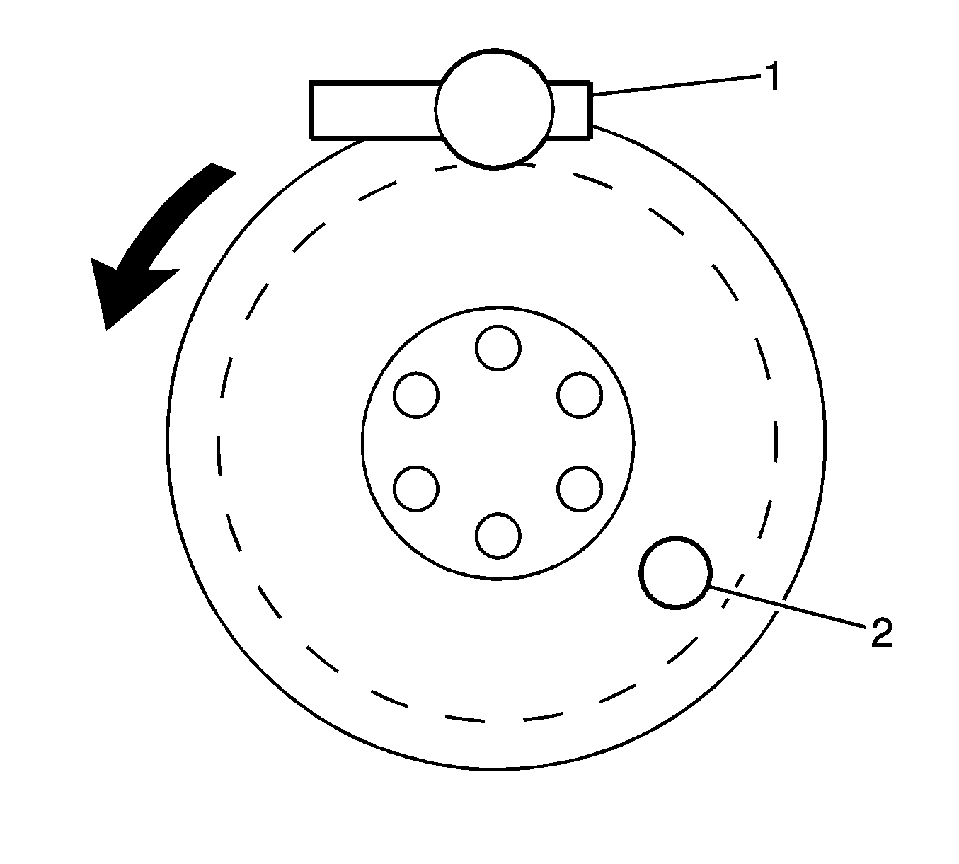
- Position the wheel on the tire changing machine with the valve stem and the tire pressure indicator sensor (2) at the 8 o'clock position and the head (1) at the 12 o'clock position. This will protect the tire pressure sensor.
- Align the high spot on the tire, marked with paint or an adhesive label, to the low spot on the wheel, which is at the valve stem.
- Rotate the wheel clockwise and push down on the tire in order to move the bottom bead to the inside of the wheel rim.
- Position the tire and the wheel with the valve stem (2) at the 4 o'clock position and the head (1) at the 12 o'clock position. This will protect the tire pressure sensor.
- Rotate the wheel counterclockwise and push down on the tire in order to move the top bead to the inside of the wheel rim.
- Inflate the tire until the beads pass over the bead humps.
- Install the valve core to the valve stem.
- Inflate the tire to the specification listed on the tire placard.
- Verify the sensor nut is tightened to the specification.
- Remove the tire and wheel assembly from the tire changing machine.
- Ensure the locating rings are visible on both sides of the tire in order to verify the tire beads are seated on the wheel.
- Balance the tire and wheel assembly.
- Inspect the tire and wheel assembly for air leaks with soapy water. Repair any air leaks.
- Install the tire and wheel assembly to the vehicle. Refer to Tire and Wheel Removal and Installation.
- Lower the vehicle.
- Register the transmitter ID. Refer to Tire Pressure Sensor Learn.
- Initialize the system. Refer to Tire Pressure Monitor System Configuration.
Note: Ensure the valve stem and the tire pressure indicator sensor are installed correctly.
Caution: When mounting the tires, use an approved tire mounting lubricant. DO NOT use silicon or corrosive base compounds to lubricate the tire bead and the wheel rim. A silicon base compound can cause the tire to slip on the rim. A corrosive type compound can cause tire or rim deterioration.
Note: Do not apply any lubricant directly to the tire pressure indicator sensor.
Warning: To avoid serious personal injury, do not stand over tire when inflating. The bead may break when the bead snaps over the safety hump. Do not exceed 275 kPa (40 psi) pressure when inflating any tire if beads are not seated. If 275 kPa (40 psi) pressure will not seat the beads, deflate, relubricate the beads and reinflate. Overinflation may cause the bead to break and cause serious personal injury.
Note: Ensure the valve core is not in the valve stem.
Caution: Refer to Fastener Caution in the Preface section.
Tighten
Tighten the nut to 4.0 N·m (35.4 lb in).
