For 1990-2009 cars only
- Remove the engine splash shield. Refer to Engine Splash Shield Replacement - Left Side.
- Drain the automatic transaxle fluid.
- Remove the automatic transaxle oil pan assembly.
- Remove the bolts and oil strainer.
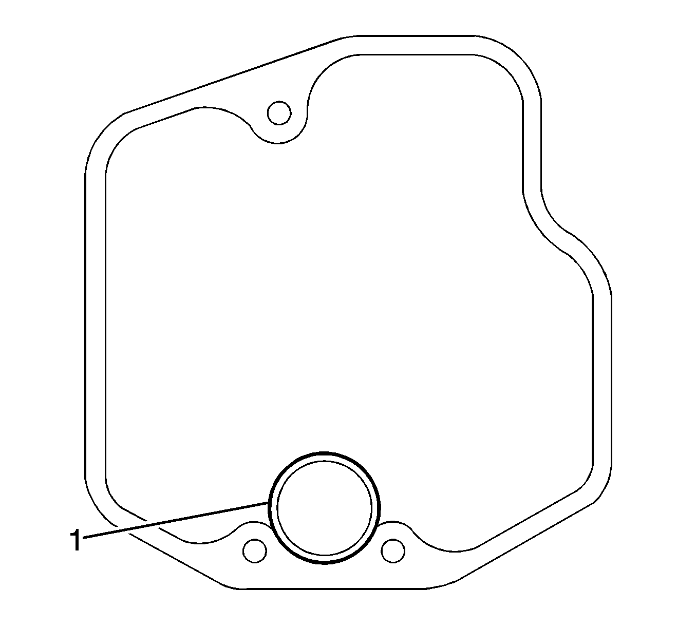
- Remove the O-ring (1) from the oil strainer.
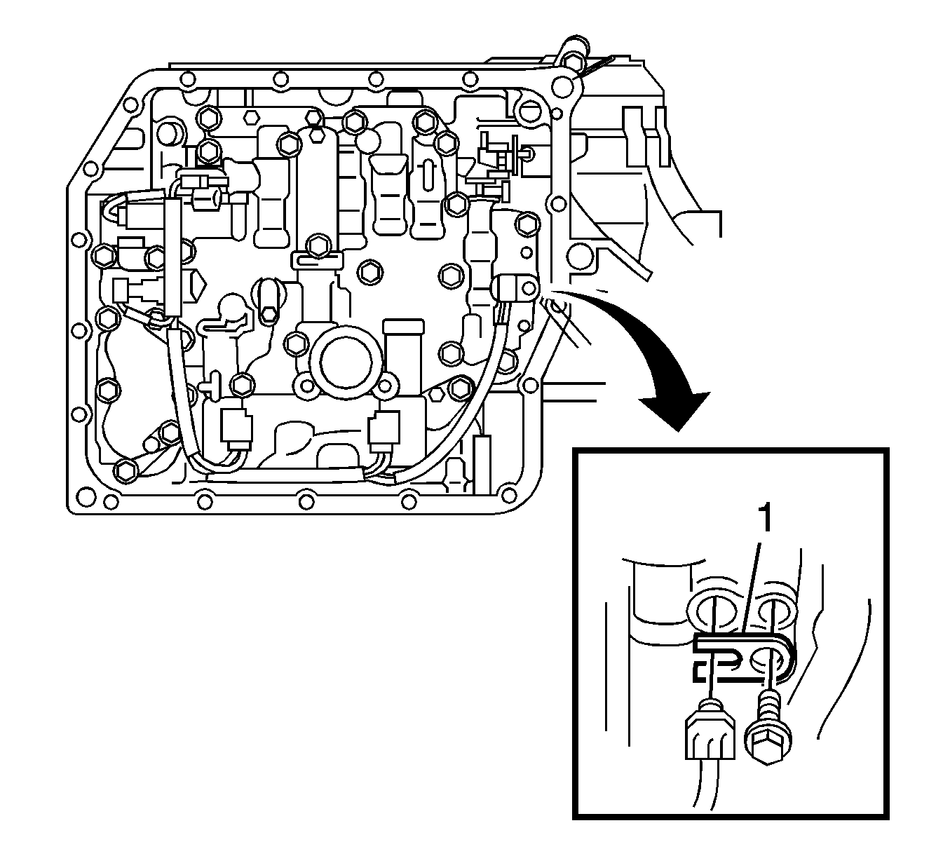
- Disconnect the connectors.
- Remove the bolt and lock plate (1), and remove the ATF temperature sensor.
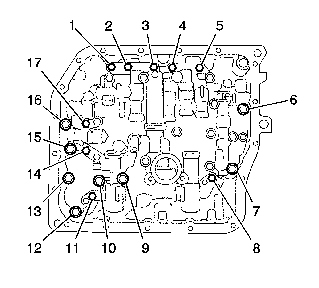
- Support the valve body and remove the bolts (1-17) and valve body.
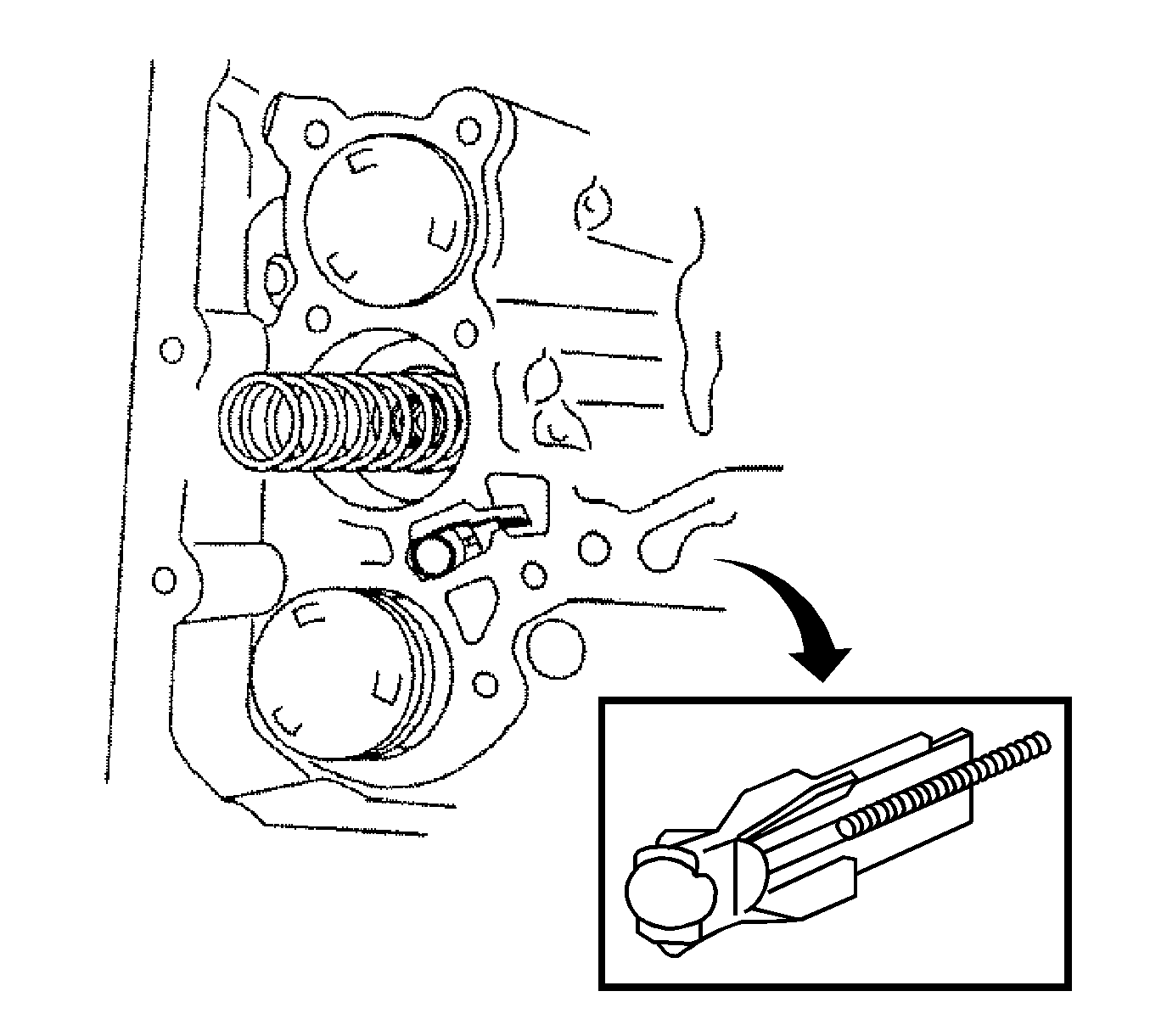
- Remove the check ball body and spring.
- Remove the manual valve from the valve body.
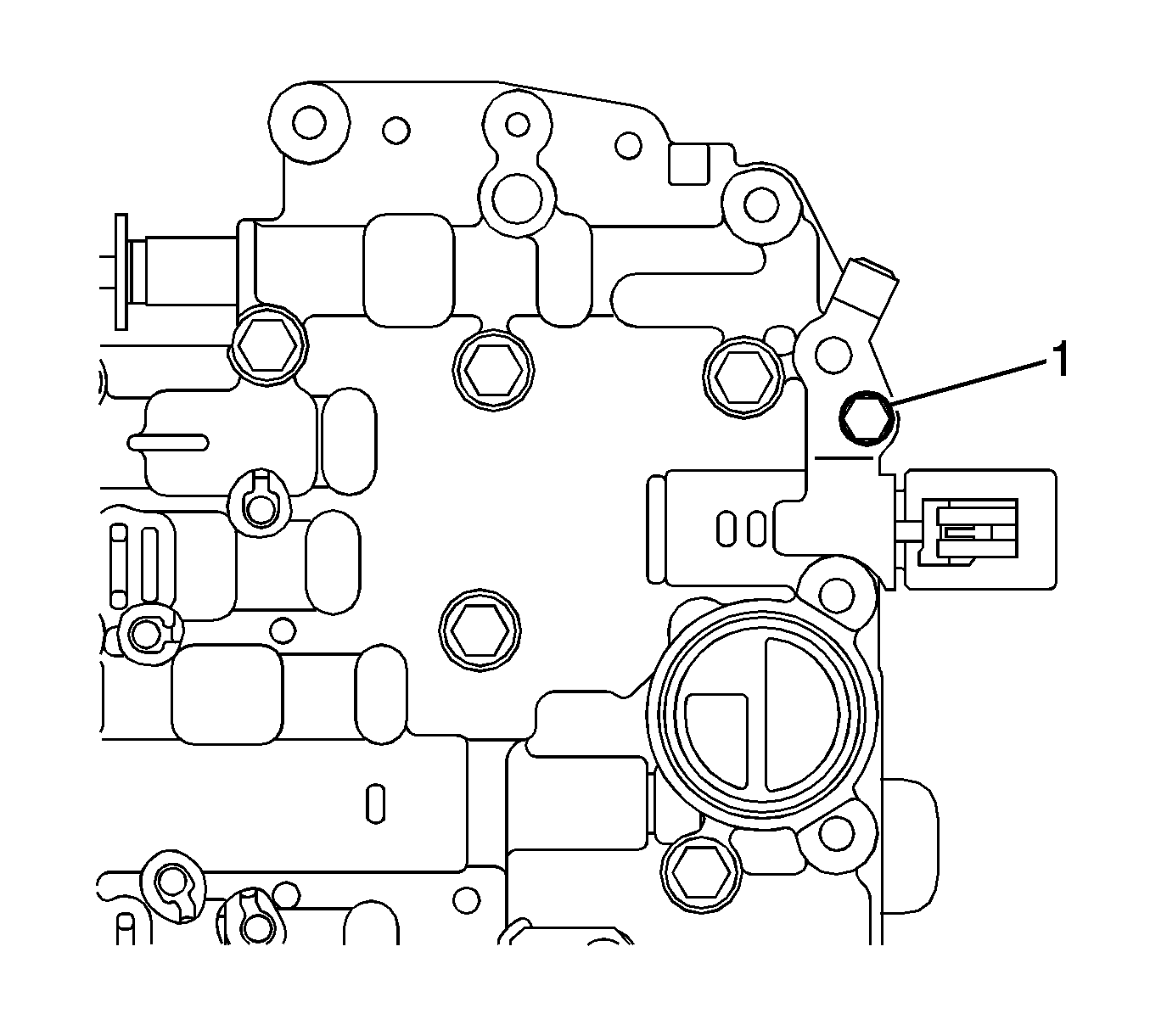
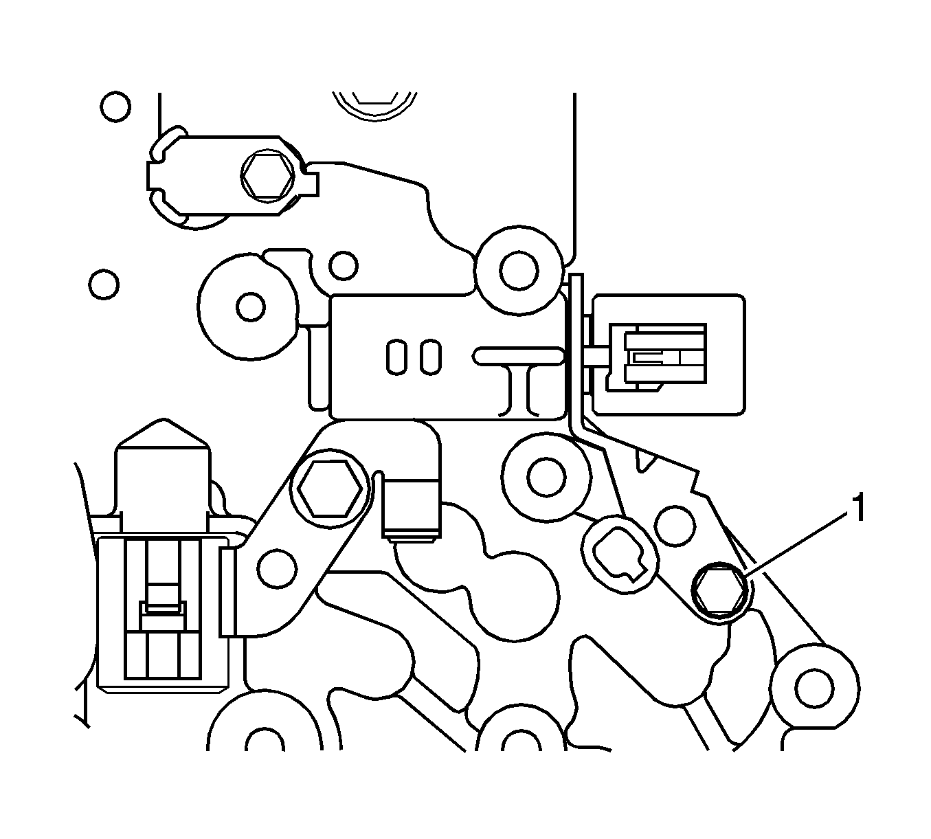
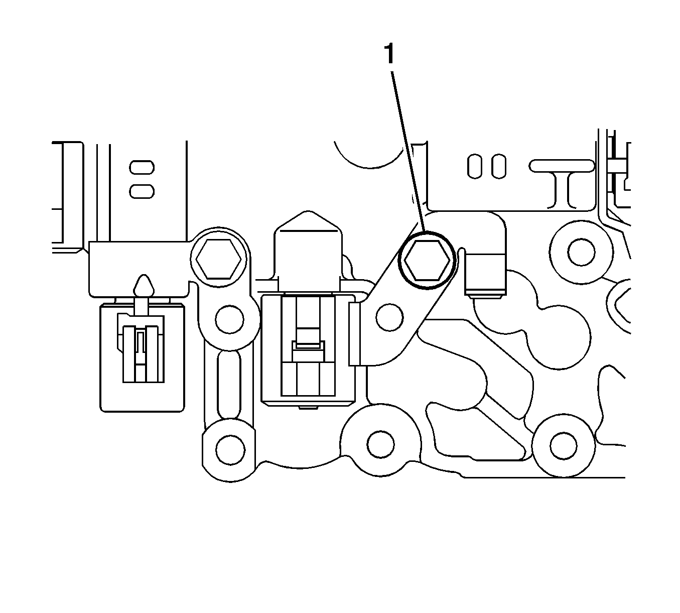
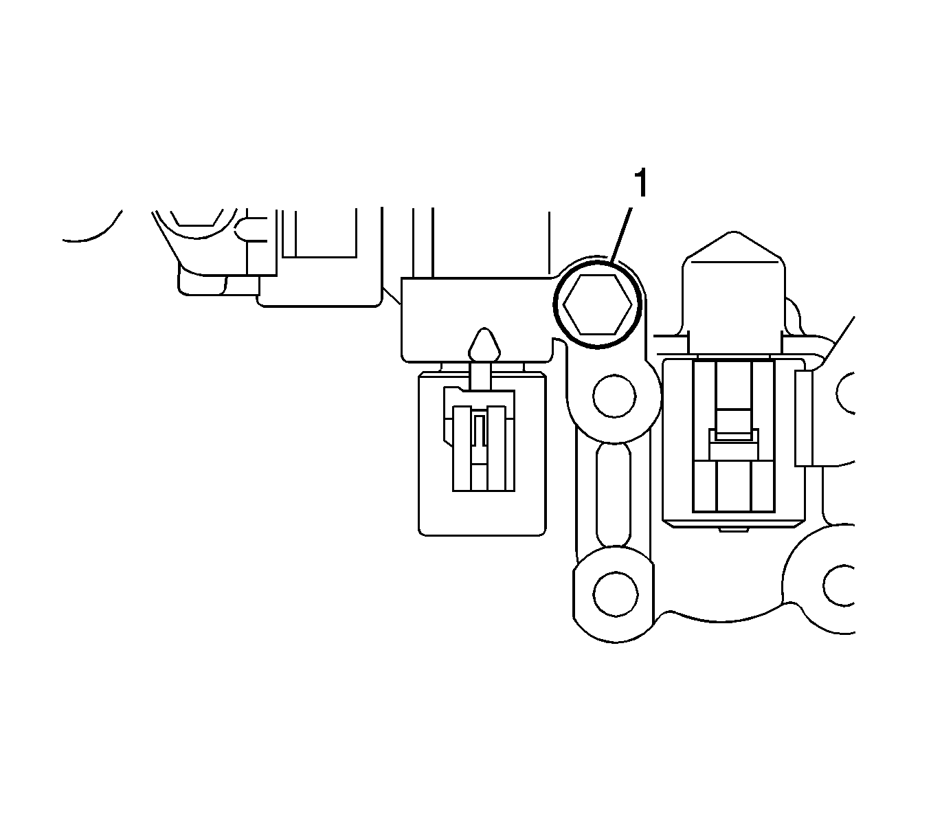
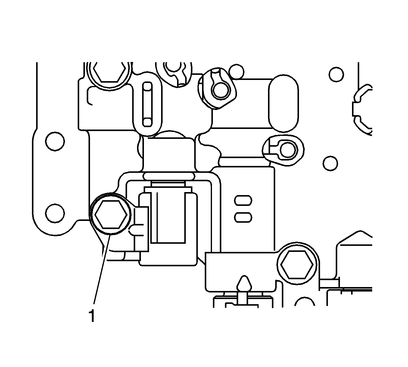
- Remove the bolt (1), plate and shift solenoid valve SLT from the valve body.
- Remove the bolt (1), plate and shift solenoid valve SL1 from the valve body.
- Remove the bolt (1) and shift solenoid valve DSL from the valve body.
- Remove the bolt (1), plate and shift solenoid valve SL2 from the valve body.
- Remove the bolt (1) and shift solenoid valve S4 from the valve body.
Note: Be careful not to drop the check valve body, spring and accumulator.
Installation Procedure
- Install the shift solenoid valve S4 to the valve body with the bolt (1) and tighten to 11 N·m (97 lb in).
- Install the shift solenoid valve SL2 to the valve body with the bolt (1) and plate and tighten to 11 N·m (97 lb in).
- Install the shift solenoid valve DSL to the valve body with the bolt (1) and tighten to 11 N·m (97 lb in).
- Install the shift solenoid valve SL1 to the valve body with the bolt (1) and plate and tighten to 7 N·m (62 lb in).
- Install the shift solenoid valve SLT to the valve body with the bolt (1) and plate and tighten to 7 N·m (62 lb in).
- Install the manual valve to the valve body.
- Install the spring and check ball body.
- Align the groove of the manual valve with the pin of lever.
- Install the bolts (1, 2, 3) and tighten to 11 N·m (97 lb in).
- Coat the O-ring of the temperature sensor with ATF WS.
- Install the ATF temperature sensor with the lock plate (1) and bolt and tighten to 7 N·m (62 lb in).
- Connect the 5 shift solenoid valve connectors.
- Coat a new O-ring with ATF WS.
- Install the O-ring (1) to the oil strainer.
- Install the oil strainer with the bolts.
- Instal the automatic transaxle oil pan assembly.
- Install the engine splash shield- left side.
- Add automatic transaxle fluid ATF WS.
Caution: Refer to Fastener Caution in the Preface section.


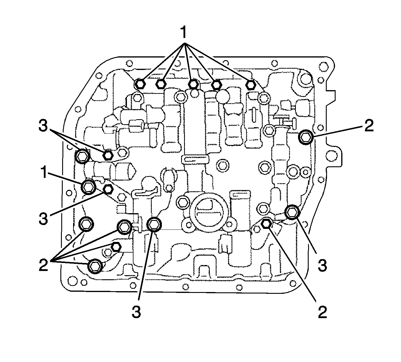
Note: Push the valve body against the accumulator piston spring and the check ball body to install it. Refer to Transmission General Specifications for bolt length A.


