Tools Required
J 45101-100
Conical Brake Rotor Washers
Adjustment Procedure
Important: Brake rotor thickness variation greater than the specification can cause brake pulsation.
- Measure the brake rotor thickness variation. Refer to
Brake Rotor Thickness Variation Measurement
.
Important: Brake rotor assembled lateral runout (LRO) greater than the specification can cause brake pulsation.
- Measure the brake rotor LRO. Refer to
Brake Rotor Assembled Lateral Runout Measurement
.

- Remove the
J 45101-100
and the wheel nuts.
- Remove the rotor from the hub.
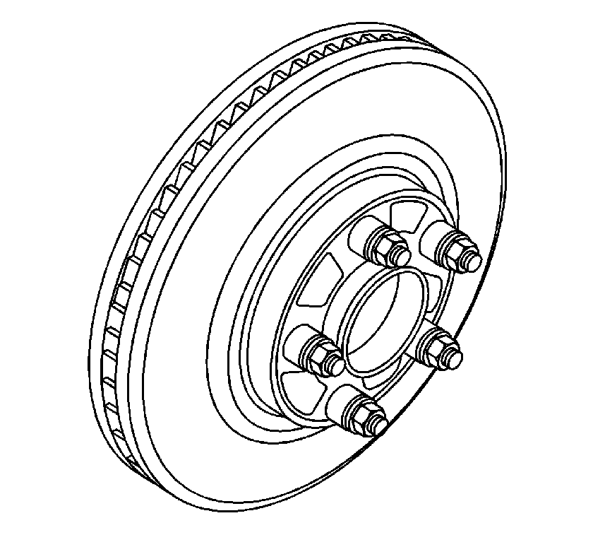
- Rotate the rotor 1 wheel stud position (72 degrees).
- Install the rotor to the hub.
- Hold the rotor firmly against the hub. Install one of the
J 45101-100
and 1 wheel nut on the top wheel stud.
- Continue to hold the rotor and tighten the wheel nut by hand.
- Install the remaining
J 45101-100
and the wheel nuts.
- Tighten the wheel nuts firmly by hand in a star pattern.
Notice: Refer to Fastener Notice in the Preface section.
- Tighten the wheel nuts in a star pattern in order to retain the rotor to the hub. Refer to
Fastener Tightening Specifications
.
- Measure the brake rotor LRO. Refer to
Brake Rotor Assembled Lateral Runout Measurement
.
- If the brake rotor LRO is greater than the specification, repeat this procedure with the rotor at the remaining 3 wheel stud positions.
- If the brake rotor LRO is greater than the specification at all 5 wheel stud positions, use an on-vehicle lathe in order to reduce the brake rotor LRO to the specification. Refer to
Brake Rotor Assembled Lateral Runout Correction - On Vehicle Lathe
.
- If the brake rotor LRO is less than the specification, complete the following steps:
| • | Use paint in order to mark the position of the brake rotor on the hub. |
| • | Install the brake caliper. |
| • | Press the brake pedal several times in order to position the brake rotor. |

