GM Service Manual Online
For 1990-2009 cars only

Function

The throttle actuator control (TAC) system delivers improved throttle response and greater reliability and eliminates the need for mechanical cable. The TAC system performs the following functions:

    • Accelerator pedal position sensing
    • Throttle positioning to meet driver and engine demands
    • Throttle position (TP) sensing
    • Internal diagnostics
    • Cruise control functions
    • Throttle control for traction control and stability control systems

The TAC system includes the following components:

    • The accelerator pedal position (APP) sensors
    • The throttle body assembly
       - TAC module, attached to the throttle body
       - TAC motor, part of TAC module
       - TP sensors, part of TAC module
    • The powertrain control module (PCM)

Accelerator Pedal Position (APP) Sensor
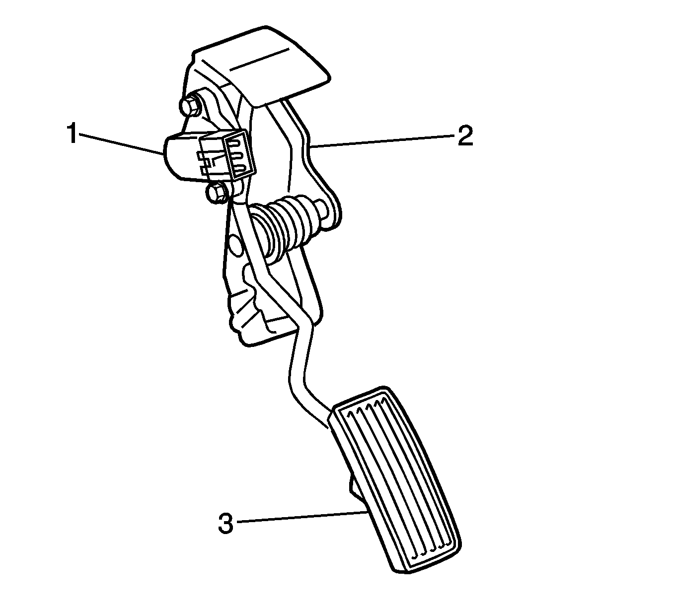

Object Number: 1455379  Size: SH

The accelerator pedal position (APP) sensor (1) is fastened to the accelerator pedal assembly (2). The APP sensor assembly contains two APP sensors that are operated by accelerator pedal (3) movement. The APP sensors 1 and 2 are potentiometer type sensors each with 3 circuits:

    • A 5-volt reference circuit
    • A low reference circuit
    • A signal circuit

The APP sensors are used to determine the pedal angle. The powertrain control module (PCM) provides each APP sensor with a 5-volt reference circuit and a low reference circuit. The APP sensors provide the PCM with signal voltage proportional to the pedal movement. APP sensor 1 signal voltage is low at the rest position and increases to near the 5-volt reference as the pedal is applied. APP sensor 2 signal is about twice the voltage of APP sensor 1 at rest, and also increases as the accelerator pedal is applied. APP sensor 2 increases at a different rate than APP sensor 1. The APP sensor 1 is responsible for providing the actual pedal position to the PCM. The PCM then sends a throttle position target value to the TAC control module. APP sensor 2 provides an accuracy check and if necessary, a backup value to the APP sensor 1. The APP sensors are not serviced separately and must be replaced with the accelerator pedal assembly

Throttle Body Assembly
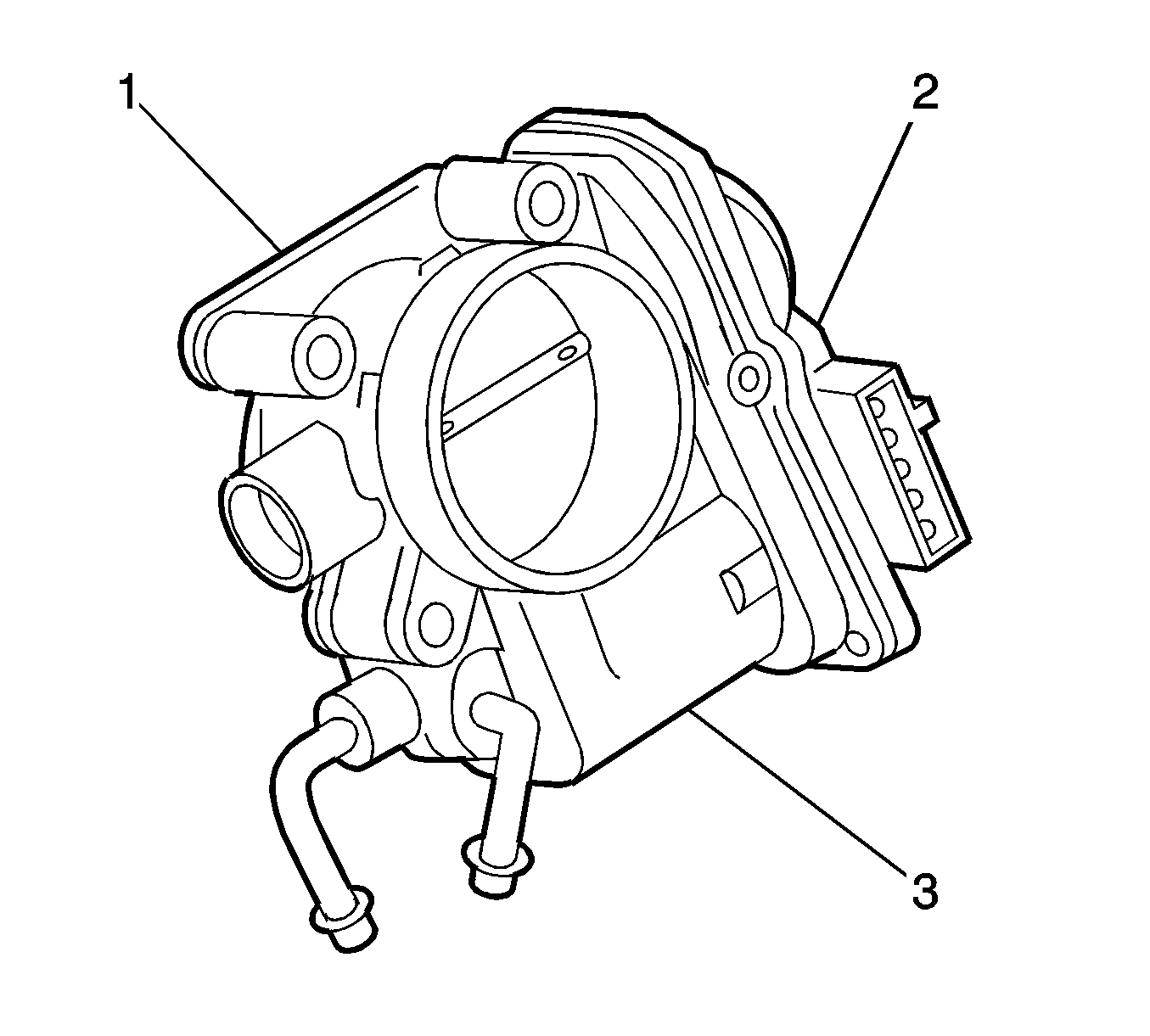

Object Number: 2037285  Size: SH
(1)Throttle Body
(2) Throttle Actuator Control (TAC) Module
(3)TAC Motor

The throttle body functions similar to a conventional throttle body with the following exceptions:

    • An electric motor opens and closes the throttle valve.
    • The TAC module is an integral part of the throttle body assembly.
    • The throttle valve is spring loaded and the default position is slightly open.
    • The throttle position (TP) sensor is integral to the TAC module assembly.

The TP sensor signals are used to determine the throttle plate or throttle valve angle. The TP sensor outputs provide the powertrain control module (PCM) with a signal voltage that is proportional to the throttle plate movement. The TP sensor is actually a Hall Effect switch. The Hall Effect switch is surrounded by a magnetic yoke that induces a flux in the magnetic field when the throttle shaft is rotated. An integrated circuit (IC) receives and converts the magnetic pulses into two separate TP signal, each with their own characteristics. Both TP sensor signal voltages are low at closed throttle and increase as the throttle opens. TP sensor 1 determines the actual throttle valve position. TP sensor 2 has a voltage that is more than twice that of TP sensor 1 at idle. TP sensor 2 provides a backup value for TP sensor 1.

Throttle Actuator Control (TAC) Module

The throttle actuator control (TAC) module is the control center for the TAC motor. In order to control engine speed, the TAC module receives a target value for throttle valve position and attempts to position the throttle valve accordingly. The TAC module achieves the correct throttle position by commanding the throttle control motor to position the throttle valve at the target value. The TAC module then sends the throttle position (TP) sensor 1 signal to the powertrain control module (PCM). The PCM then compares the TP sensor value to the target value. If necessary, the PCM sends a revised target position to the TAC module and the throttle control motor is moved slightly in order to obtain the exact desired position. The TAC module, motor, or TP sensor are not serviced separately and must be replaced with the throttle body assembly.

Powertrain Control Module

The powertrain control module (PCM) determines the drivers intent and then calculates the appropriate throttle response. The accelerator pedal position (APP) sensor 1 enables the PCM to provide a target value to the TAC module in response to accelerator pedal movement. The throttle position (TP) sensor 1 input enables the PCM to determine whether the throttle valve opening is correct for the desired engine operation at that moment.

Modes of Operation

Normal Mode

During the operation of the throttle actuator control (TAC) system, several modes or functions are considered normal. The following modes may be entered during normal operation:

    • Normal control with APP values--In this operating mode, the PCM controls throttle movement according to APP sensor input. This mode will continue until an error is detected in the APP sensor input or other critical data.
    • Learned idle mode--When ever the powertrain control module (PCM) recognizes the learned idle throttle position (TP) value, the engine operates in the learned idle mode. In the learned idle mode, the PCM uses stored engine performance settings in order to provide the best quality idle for all idle speed situations.
    • Cold engine start mode--The throttle valve has a default start position that ensures improved cold engine starting and cold engine operation.

Reduced Engine Power Mode

When the PCM detects a condition with the TAC system, the PCM may enter a reduced engine power mode. If the condition that initiated the reduced power mode is corrected, normal throttle operation will return once the ignition has been turned OFF to ON. Reduced engine power can be enabled with the following conditions:

    • Limited throttle mode--The PCM will continue to use the accelerator pedal for throttle control; however, vehicle acceleration is limited. In this mode at least one APP sensor signal is still deemed to be accurate.
    • Limited throttle mode--The PCM has detected an error, but will continue to use the accelerator pedal for throttle control; however, the maximum throttle opening is limited.
    • Forced idle mode--The PCM will perform the following actions:
       - Limits engine speed to near idle by cutting off the current to the throttle motor, leaving the throttle valve at the return spring idle position. The PCM will continue to use APP sensor input, but will only modify fuel and spark in order to maintain some driveability. This mode is entered when a fault is detected in either TP sensor or the TAC motor control system
       - Limits engine speed to idle because both APP sensor signals are determined to be erroneous.
    • Traction Control or Stability Control mode--The PCM will temporarily disable throttle control from driver input, APP sensor input, in order to perform a traction or stability control action.
    • Engine shutdown mode--The PCM will disable fuel and de-energize the TAC system.