DIRECT FIRE IGNITION SYSTEMS DIAGNOSIS INFORMATION

VEHICLES AFFECTED: ALL VEHICLES WITH 2.0L, 2.5L AND 2.8L ENGINES, ----------------- WITH DIS
Recent studies of returned parts have shown that a high percentage of Direct Ignition System (DIS) modules which have been replaced are not defective. This is particularly true on the 2.5L engine. Before replacing a module in the future, please review the following information:
1. If the customer comment is intermittent long crank, or intermittent no- start, the problem is most likely not in the ignition system. Verify this by a) testing for spark with the ST-125 tool while cranking, and b) testing for RPM reference signal to Electronic Control Module (ECM), by reading RPM using a "Scan" tool while cranking. This check verifies the correct operation of the ignition system. This can also be checked on Chart A-3 (Cranks But Won't Run) of either Section 6E2 or 6E3 of the Service Manual.
Also, remember that an inoperative fuel pump relay may lead to long crank times when the engine is cold.
2. An intermittent miss, backfire, or hesitation may be caused by a defective coil. Check the coil as shown in Section 6E2-C4 (TBI) or 6E3-C4 (PFI) of the Service Manual.
3. The coil, module and sensor are available separately from GMSPO. The coil/module assembly need not be replaced, and will no longer be serviced.
4. For any intermittent condition found, the six-way connector to the module should be checked for proper connection. This check should include:
a. Check for presence of weather pack seal. If present, check for damage (cuts, rib broken). Replace if necessary.
b. Check terminal alignment in connector cavities. All terminals should be at the same height. Any terminal "backed out" of cavity should be properly seated.
c. Visually check inside ramp of terminal (tonque) in connector. If ramp is bent or damaged, the terminal should be replaced. Do not place any object (paper clip, loose terminal, etc.) inside the terminal.
d. Make sure connector locking arm locks over ramp on module when making connection.
5. Under no circumstances should the crankshaft sensor or module baseplate be shimmed. This will not improve any of the above conditions, and could cause other problems.
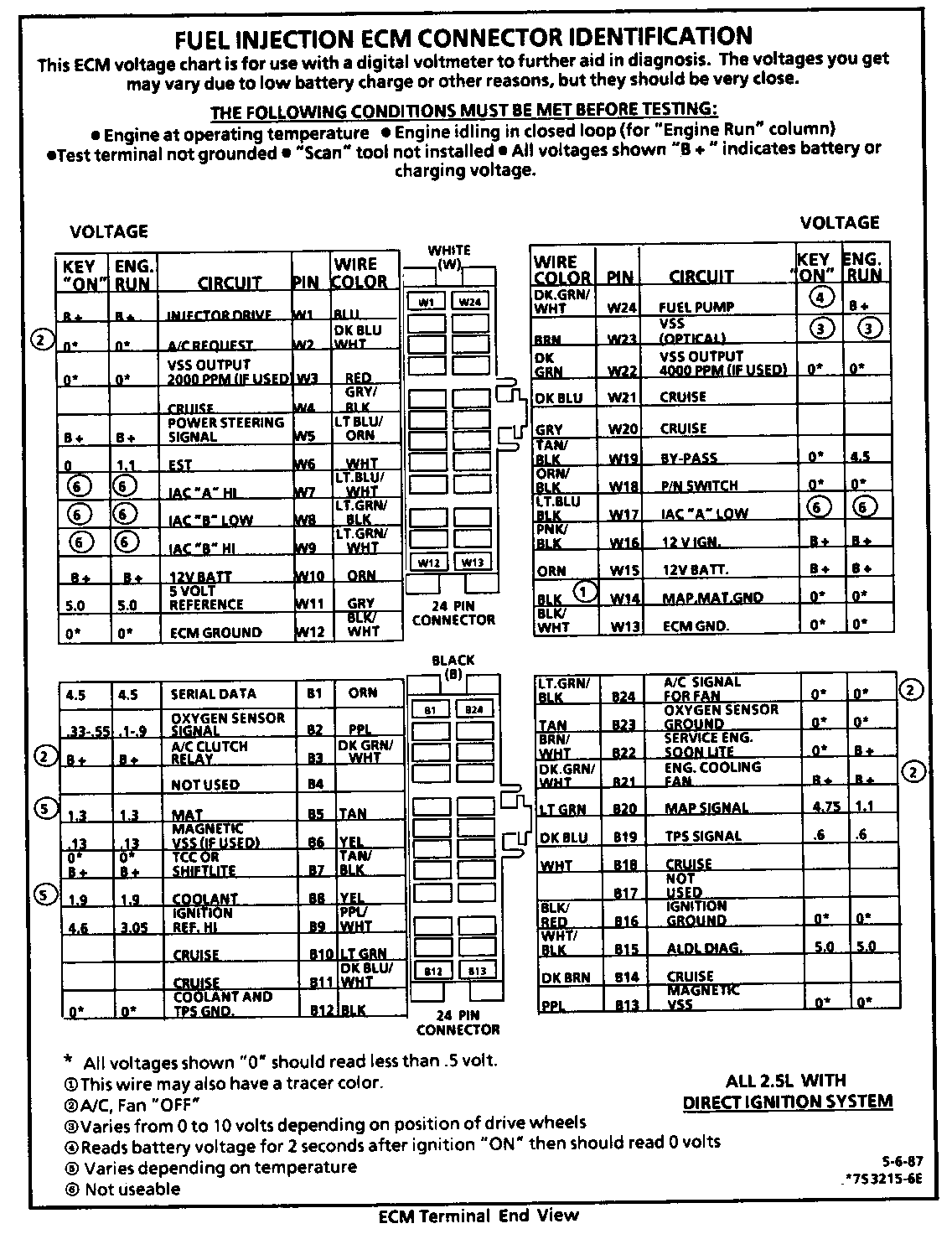
6. The attached chart replaces the existing chart on page 6E2-A-6 of the A, N and P Series Service Manuals. The voltage reading for terminal "B9" was incorrect.
7. Coil mounting screws to baseplate should be torqued to 4-5 N.m. Higher torque may strip the aluminum baseplate.
General Motors bulletins are intended for use by professional technicians, not a "do-it-yourselfer". They are written to inform those technicians of conditions that may occur on some vehicles, or to provide information that could assist in the proper service of a vehicle. Properly trained technicians have the equipment, tools, safety instructions and know-how to do a job properly and safely. If a condition is described, do not assume that the bulletin applies to your vehicle, or that your vehicle will have that condition. See a General Motors dealer servicing your brand of General Motors vehicle for information on whether your vehicle may benefit from the information.
