System Description
The control module tests the evaporative emission (EVAP) system for a large leak. The control module monitors the fuel tank pressure (FTP) sensor signal to determine the EVAP system vacuum level. When the conditions for running are met, the control module commands the EVAP canister purge valve OPEN and the EVAP vent valve CLOSED . This allows engine vacuum to enter the EVAP system. At a calibrated time, or vacuum level, the control module commands the EVAP canister purge valve closed, sealing the system, and monitors the FTP sensor input in order to determine the EVAP system vacuum level. If the system is unable to achieve the calibrated vacuum level, or the vacuum level decreases too rapidly, this DTC sets.
The following table illustrates the relationship between the ON and OFF states, and the OPEN or CLOSED states of the EVAP canister purge and vent valves.
Control Module Command | EVAP Canister Purge Valve | EVAP Canister Vent Valve |
|---|---|---|
ON | Open | Closed |
OFF | Closed | Open |
Conditions for Running the DTC
| • | DTCs P0107, P0108, P0112, P0113, P0116, P0117, P0118, P0122, P0123, P0125, P0452, P0453 are not set. |
| • | The engine is running. |
| • | The ignition voltage is between 10-18 volts. |
| • | The barometric pressure (BARO) is more than 75 kPa. |
| • | The fuel level is between 15-85 percent. |
| • | The engine coolant temperature (ECT) is between 4-30°C (39-86°F). |
| • | The intake air temperature (IAT) is between 4-30°C (39-86°F). |
| • | The start-up ECT and IAT are within 9°C (16°F) of each other. |
| • | The vehicle speed sensor (VSS) is less than 121 km/h (75 mph). |
Conditions For Setting the DTC
The EVAP system is not able to achieve or maintain vacuum during the diagnostic test.
Action Taken When the DTC Sets
| • | The control module illuminates the malfunction indicator lamp (MIL) on the second consecutive ignition cycle that the diagnostic runs and fails. |
| • | The control module records the operating conditions at the time the diagnostic fails. The first time the diagnostic fails, the control module stores this information in the Failure Records. If the diagnostic reports a failure on the second consecutive ignition cycle, the control module records the operating conditions at the time of the failure. The control module writes the operating conditions to the Freeze Frame and updates the Failure Records. |
Conditions for Clearing the MIL/DTC
| • | The control module turns OFF the malfunction indicator lamp (MIL) after 3 consecutive ignition cycles that the diagnostic runs and does not fail. |
| • | A current DTC, Last Test Failed, clears when the diagnostic runs and passes. |
| • | A history DTC clears after 40 consecutive warm-up cycles, if no failures are reported by this or any other emission related diagnostic. |
| • | Clear the MIL and the DTC with a scan tool. |
Diagnostic Aids
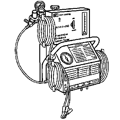
| • | To help locate intermittent leaks, use the J 41413-200 Evaporative Emissions System Tester (EEST) to introduce smoke into the EVAP system. Move all EVAP components while observing smoke with the J 41413-SPT High Intensity White Light. |
| • | A temporary blockage in the EVAP purge solenoid, purge pipe or EVAP canister could cause an intermittent condition. Inspect and repair any restriction in the EVAP system. |
| • | To improve the visibility of the smoke exiting the EVAP system, observe the suspected leak area from different angles with theJ 41413-SPT . |
| • | Reviewing the Failure Records vehicle mileage since the diagnostic test last failed may help determine how often the condition that caused the DTC to be set occurs. This may assist in diagnosing the condition. |
| • | A loose, missing, incorrect, or damaged fuel fill cap may cause this DTC to set. |
| • | For intermittent conditions refer to Intermittent Conditions . |
Test Description
The numbers below refer to the step numbers on the diagnostic table.
-
This test verifies that the EVAP purge solenoid is electrically functional.
-
This test verifies that the EVAP vent solenoid is electrically functional.
-
Introducing smoke in 15 second intervals may allow smaller leak areas to be more noticeable. When the system is less pressurized, the smoke will sometimes escape in a more condensed manner.
-
This test verifies that the FTP sensor is accurate. An FTP sensor that does not correctly respond to vacuum, or pressure may cause this DTC to set.
Step | Action | Values | Yes | No | ||||||||||
|---|---|---|---|---|---|---|---|---|---|---|---|---|---|---|
Schematic Reference: Engine Controls Schematics Evaporative Emissions Hose Routing Diagram Connect End View Reference: Powertrain Control Module Connector End Views or Engine Controls Connector End Views | ||||||||||||||
1 | Did you perform the Diagnostic System Check-Engine Controls? | -- | Go to Step 2 | |||||||||||
2 |
Did you find and correct the condition? | -- | Go to Step 38 | Go to Step 3 | ||||||||||
Do you hear or feel a clicking from the EVAP purge solenoid when it is commanded to 50 percent? | -- | Go to Step 4 | Go to Step 5 | |||||||||||
Command the EVAP vent solenoid ON and OFF with the scan tool. Do you hear or feel a click as the EVAP vent solenoid is commanded ON and OFF? | -- | Go to Step 9 | Go to Step 7 | |||||||||||
5 |
Does the test lamp illuminate? | -- | Go to Step 6 | Go to Step 29 | ||||||||||
6 |
Does the test lamp illuminate or pulsate when the EVAP purge solenoid is commanded to 50 percent and turn OFF when the EVAP purge solenoid is commanded to 0 percent? | -- | Go to Step 23 | Go to Step 21 | ||||||||||
7 |
Does the test lamp illuminate? | -- | Go to Step 8 | Go to Step 30 | ||||||||||
8 |
Does the test lamp illuminate? | -- | Go to Step 24 | Go to Step 22 | ||||||||||
9 |
Important: Larger volume fuel tanks and/or those with lower fuel levels may require several minutes for the floating indicator to stabilize.
Is the floating indicator below the red flag? | -- | Go to Step 12 | Go to Step 10 | ||||||||||
|
Important: Ensure that the vehicle underbody temperature is similar to the ambient temperature and allow the surrounding air to stabilize before starting the diagnostic procedure. System flow will be less with higher temperatures.
Did you locate and repair a leak source? | -- | Go to Step 38 | Go to Step 11 | |||||||||||
11 |
Did you locate and repair a leak source? | -- | Go to Step 38 | Go to Step 12 | ||||||||||
Is the scan tool FTP Sensor parameter within the specified value of the J 41413-200 pressure/vacuum gage? | 1 in H2O | Go to Step 13 | Go to Step 25 | |||||||||||
13 |
Is the FTP Sensor parameter more than the second specified value? | 10 in H2O 5 in H2O | Go to Step 14 | Go to Step 25 | ||||||||||
14 |
Is the FTP Sensor parameter Less than the specified value? | 1 in H2O | Go to Step 15 | Go to Step 17 | ||||||||||
15 |
Is the FTP parameter on a scan tool within the specified value of the vacuum/pressure gage on the J 41413-200 , until the vacuum reached the abort limit on a scan tool. | 1 in H2O | Go to Step 16 | Go to Step 25 | ||||||||||
16 | Did the FTP parameter on a scan tool display more than the specified value? | 3.2 V | Go to Diagnostic Aids | Go to Step 25 | ||||||||||
17 | Disconnect the EVAP purge vacuum source from the EVAP purge solenoid. Is the FTP sensor parameter less than the specified value? | 1 in H2O | Go to Step 28 | Go to Step 18 | ||||||||||
18 | Disconnect the EVAP purge pipe from the EVAP purge solenoid. Is the FTP Sensor parameter less than the specified value? | 1 in H2O | Go to Step 33 | Go to Step 19 | ||||||||||
19 | Disconnect the EVAP purge pipe at the EVAP canister. Is the FTP Sensor parameter Less than the specified value? | 1 in H2O | Go to Step 31 | Go to Step 20 | ||||||||||
20 | Disconnect the EVAP vapor pipe at the EVAP canister. Is the FTP Sensor parameter Less than the specified value? | 1 in H2O | Go to Step 35 | Go to Step 32 | ||||||||||
21 | Test the control circuit of the EVAP purge solenoid for an open or for a short to voltage. Refer to Circuit Testing and Wiring Repairs in Wiring Systems. Did you find and correct the condition? | -- | Go to Step 38 | Go to Step 27 | ||||||||||
22 | Test the control circuit of the EVAP vent solenoid for an open or for a short to voltage. Refer to Circuit Testing and Wiring Repairs in Wiring Systems. Did you find and correct the condition? | -- | Go to Step 38 | Go to Step 27 | ||||||||||
23 | Test for an intermittent and for a poor connection at the EVAP canister purge solenoid. Refer to Testing for Intermittent Conditions and Poor Connections and Connector Repairs in Wiring Systems. Did you find and correct the condition? | -- | Go to Step 38 | Go to Step 33 | ||||||||||
24 | Test for an intermittent and for a poor connection at the EVAP vent solenoid. Refer to Testing for Intermittent Conditions and Poor Connections and Connector Repairs in Wiring Systems. Did you find and correct the condition? | -- | Go to Step 38 | Go to Step 34 | ||||||||||
25 | Test the low reference circuit of the FTP sensor for an open or high resistance. Refer to Circuit Testing and Wiring Repairs in Wiring Systems. Did you find and correct the condition? | -- | Go to Step 38 | Go to Step 26 | ||||||||||
26 | Test for an intermittent and for a poor connection at the FTP sensor. Refer to Testing for Intermittent Conditions and Poor Connections and Connector Repairs in Wiring Systems. Did you find and correct the condition? | -- | Go to Step 38 | Go to Step 36 | ||||||||||
27 | Test for an intermittent and for a poor connection at the control module. Refer to Testing for Intermittent Conditions and Poor Connections and Connector Repairs in Wiring Systems. Did you find and correct the condition? | -- | Go to Step 38 | Go to Step 37 | ||||||||||
28 | Repair the pinched or obstructed EVAP purge solenoid vacuum source. Did you complete the repair? | -- | Go to Step 38 | -- | ||||||||||
29 |
Did you complete the repair? | -- | Go to Step 38 | -- | ||||||||||
30 | Repair the open or short to ground in the ignition 1 voltage circuit of the EVAP vent solenoid. Refer to Wiring Repairs in Wiring Systems. Replace the fuse as necessary. Did you complete the repair? | -- | Go to Step 38 | -- | ||||||||||
31 | Repair the restriction in the EVAP purge pipe. Refer to Evaporative Emission System Cleaning . Did you complete the repair? | -- | Go to Step 38 | -- | ||||||||||
32 | Repair the restriction in the EVAP vapor pipe. Did you complete the repair? | -- | Go to Step 38 | -- | ||||||||||
33 | Replace the EVAP purge solenoid. Refer to Evaporative Emission Canister Purge Solenoid Valve Replacement . Did you complete the replacement? | -- | Go to Step 38 | -- | ||||||||||
34 | Replace the EVAP vent solenoid. Refer to Evaporative Emission Canister Vent Solenoid Valve Replacement . Did you complete the replacement? | -- | Go to Step 38 | -- | ||||||||||
35 | Replace the EVAP canister. Refer to Evaporative Emission Canister Replacement . Did you complete the replacement? | -- | Go to Step 38 | -- | ||||||||||
36 | Replace the FTP sensor. Refer to Fuel Tank Pressure Sensor Replacement . Did you complete the replacement? | -- | Go to Step 38 | -- | ||||||||||
37 | Replace the powertrain control module (PCM). Refer to Powertrain Control Module Replacement . Did you complete the replacement? | -- | Go to Step 38 | -- | ||||||||||
38 |
Important: Larger volume fuel tanks and/or those with lower fuel levels may require several minutes for the floating indicator to stabilize.
Is the floating indicator below the red flag? | -- | Go to Step 39 | Go to Step 10 | ||||||||||
39 |
Does the pressure decrease? | -- | Go to Step 40 | Go to Step 17 | ||||||||||
40 | Observe the FTP sensor parameter, with a scan tool. Is the scan tool FTP parameter within the specified value of the J 41413-200 pressure/vacuum gage? | 1 in H2O | Go to Step 41 | Go to Step 25 | ||||||||||
41 | Observe the Capture Info with a scan tool. Are there any DTCs that have not been diagnosed? | -- | System OK | |||||||||||
