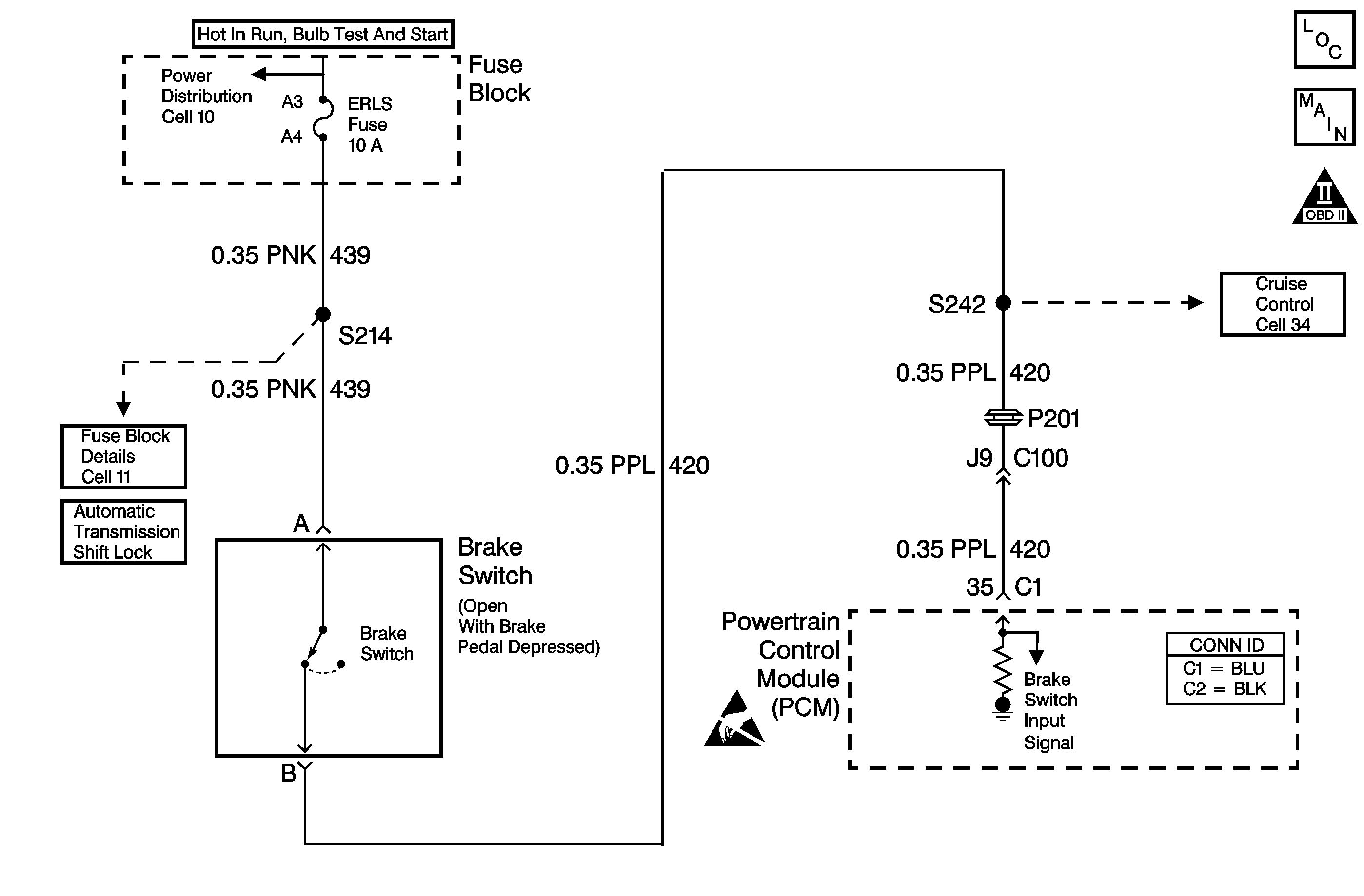
Circuit Description
The brake switch indicates brake pedal status to the powertrain control module (PCM). The normally-closed switch supplies battery voltage on circuit 420 to the PCM. Applying the brake pedal opens the switch, interrupting voltage to the PCM. Releasing the brake pedal resumes voltage to the PCM. Brake pedal resumes voltage to the PCM. If the PCM receives 0 volts at the brake switch input with the torque converter clutch (TCC) engaged, the PCM de-energizes the torque converter clutch solenoid valve (TCC solenoid valve) . The PCM disregards the brake switch input for TCC scheduling if there is a brake switch circuit fault. Refer to Diagnostic Aids.
When the PCM detects an open switch circuit (0 volts, low input) during accelerations, then DTC P0719 sets. DTC P0719 is a type C DTC.
Conditions for Running the DTC
The ignition is in the ON position.
Conditions for Setting the DTC
DTC P0719 sets if the PCM detects an open brake switch or circuit (0 volts) for 15 minutes and the following conditions occur eight consecutive times:
| • | The vehicle speed is less than 8 km/h (5 mph) |
| • | then the vehicle speed is 8-32 km/h (5-20 mph) for 3 seconds |
| • | then the vehicle speed is greater than 32 km/h (20 mph) for 6 seconds. |
Action Taken When the DTC Sets
| • | The PCM does not illuminate the malfunction indicator lamp (MIL). |
| • | The PCM records the operating conditions when the Conditions for Setting the DTC are met. The PCM stores this information as Failure Records. |
| • | The PCM stores DTC P0719 in PCM history. |
Conditions for Clearing the DTC
| • | A scan tool can clear the DTC. |
| • | The PCM clears the DTC from PCM history if the vehicle completes 40 warm-up cycles without a non-emission related diagnosis fault occurring. |
Diagnostic Aids
| • | If the PCM detects a brake switch fault, then the brake switch input is disregarded for TCC scheduling. The PCM then uses throttle position and vehicle speed input to determine TCC application and release. Use of these inputs may result in a noticeable, harsh apply, or abrupt release of the TCC. |
| • | Inspect the brake switch for proper adjustment. |
| • | Inspect the connectors at the PCM, the brake switch and all other circuit connecting points for an intermittent condition. Refer to Testing for Intermittent Conditions and Poor Connections in Wiring Systems. |
| Inspect the circuit wiring for an intermittent condition. Refer to Testing Testing for Electrical Intermittents in Wiring Systems. |
Test Description
The numbers below refer to the step numbers on the diagnostic table.
-
If you disconnect the brake switch connector and observe the Scan Tool brake switch status change, with the jumper wire in place, then a brake switch is the only possible cause.
-
A short to ground in the power feed circuit would open the ERLS fuse.
-
If the brake switch is properly adjusted, then the brake switch must be replaced.
-
Replace the PCM only after you have completed the preceding diagnostic steps.
Step | Action | Value(s) | Yes | No | ||||||
|---|---|---|---|---|---|---|---|---|---|---|
1 | Did you perform the Powertrain Diagnostic System Check? | -- | ||||||||
Important: Before clearing the DTC, use the Scan Tool in order to record the Failure Records. Using the Clear Info function erases the Failure Records from the PCM. Did the Brake Switch status change from Open to Closed? | -- | |||||||||
Refer to Circuit Testing and Wiring Repairs in Wiring Systems. Was the fuse open? | -- | |||||||||
4 |
Important:: The condition that affects this circuit may exist in other connecting branches of the circuit. Refer to Power Distribution Schematics Test the power feed circuit (CKT 439) of the brake switch for a short to ground. Refer to Circuit Testing and Wiring Repairs in Wiring Systems. Did you find and correct the condition? | -- | -- | |||||||
Refer to Stop Lamp Switch Adjustment in Hydraulic Brakes. Did the brake switch require adjustment? | -- | |||||||||
6 | Test the input circuit (CKT 420) of the brake switch for an open. Refer to Circuit Testing and Wiring Repairs in Wiring Systems. Did you find and correct a condition? | -- | ||||||||
7 | Replace the brake switch. Refer to Stop Lamp Switch Replacement in Hydraulic Brakes. Did you complete the replacement. | -- | -- | |||||||
Replace the PCM. Refer to Powertrain Control Module Replacement/Programming in Engine Controls. Did you complete the replacement? | -- | -- | ||||||||
9 | Perform the following procedure in order to verify the repair:
Has the test run and passed? | -- | System OK |
