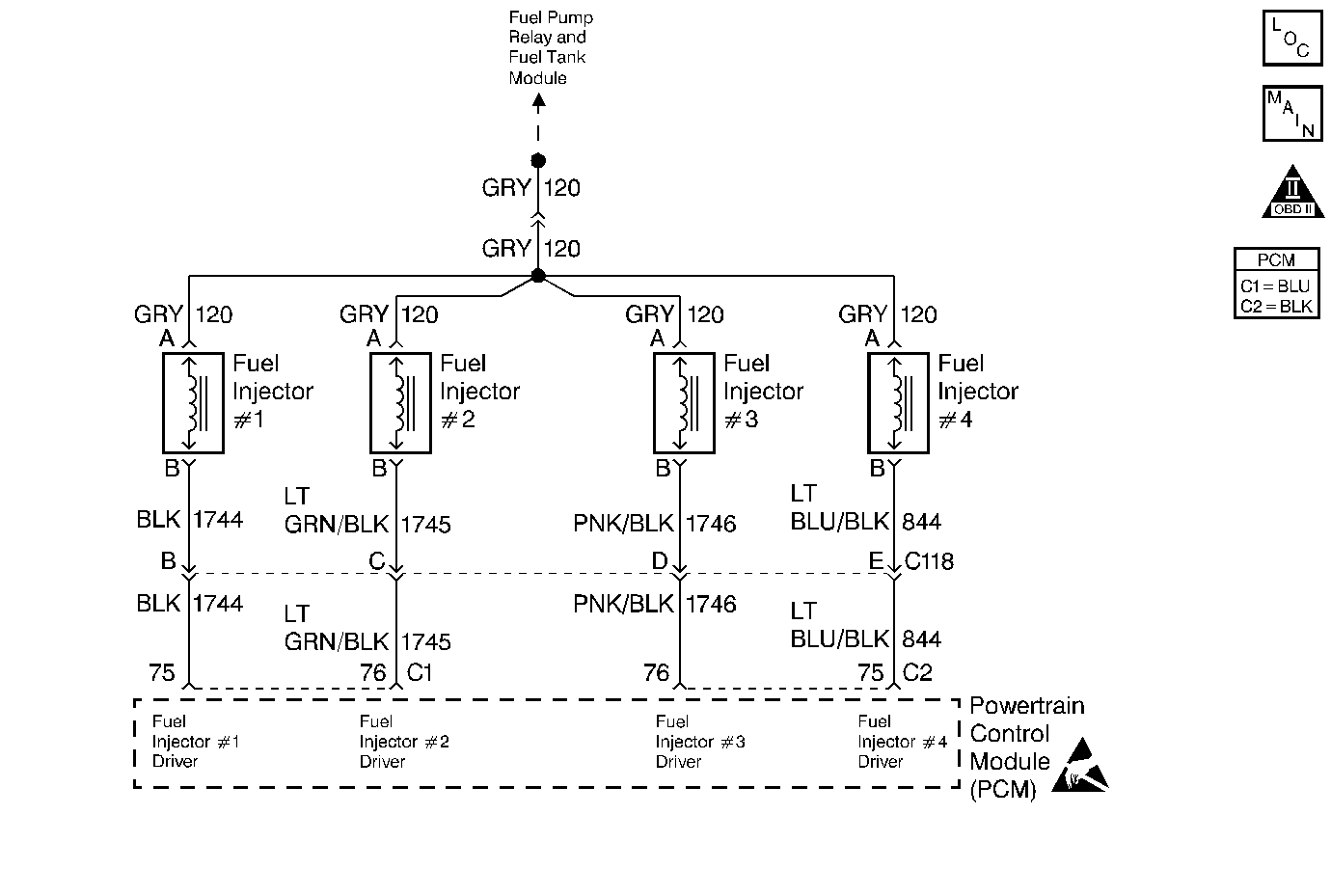
Circuit Description
The Powertrain Control Module (PCM) has four fuel injector driver circuits, each of which controls a fuel injector. The PCM monitors the current in each driver circuit and is able to control the driver circuit. The current through each driver can rise to a peak of 2 amps in order to quickly open the fuel injectors. The current can reduce to 1/2 amp to hold the fuel injectors open. This is called peak and hold. If the current cannot reach a 2-amp peak, a DTC is set. This DTC is also set if a fuel injector driver is shorted to voltage.
Conditions for Setting the DTC
| • | Injector current is less than 4 amps. |
| • | Battery voltage is more than 9 volts. |
| • | Above conditions met for 7 seconds. |
Action Taken When the DTC Sets
| • | The malfunction indicator lamp (MIL) illuminates. |
| • | The PCM records the operating conditions at the time when the diagnostic fails. This information stores in the Freeze Frame and Failure Records buffers. |
| • | A history DTC stores. |
| • | The coolant fan turns ON. |
Conditions for Clearing the MIL/DTC
| • | The MIL will turn OFF after three consecutive ignition cycles in which the diagnostic runs without a fault. |
| • | A history DTC will clear after 40 consecutive warm-up cycles without a fault. |
| • | The MIL/DTCs can be cleared by using the scan tool. |
Diagnostic Aids
An injector driver circuit that is open or shorted to voltage will cause a DTC P0200 to set and will also cause a misfire due to an inoperative injector. A misfire DTC should also be set indicating which injector is inoperative.
Long term and short term fuel trims that are excessively high or low are a good indication that an injector is malfunctioning. Use Fuel Injector Solenoid Coil Test - Engine Coolant Temperature Between 10-35 Degrees C (50-95 Degrees F) 2.4L or Fuel Injector Solenoid Coil Test - Engine Coolant Temperature Between 10-35 Degrees C (50-95 Degrees F) 2.2L to check for malfunctioning injectors.
Test Description
The numbers below refer to the step numbers on the Diagnostic Table.
-
The Powertrain OBD System Check prompts you to complete some of the basic checks and to store the freeze frame and failure records data on the scan tool if applicable. This creates an electronic copy of the data captured when the malfunction occurred. The scan tool stores this data on the scan tool for later reference.
-
This step tests the harness wiring and for the PCM control of the fuel injectors by using the J 34730-2A fuel injector test light. If the tests light blinks, this indicates that the PCM and the wiring to the fuel injectors are OK. Fuel Injector Solenoid Coil Test - Engine Coolant Temperature Between 10-35 Degrees C (50-95 Degrees F) 2.4L or Fuel Injector Solenoid Coil Test - Engine Coolant Temperature Between 10-35 Degrees C (50-95 Degrees F) 2.2L will check if the fuel injectors are malfunctioning.
-
Whether the test light was ON steady or OFF while cranking the engine, this step narrows the malfunction down to just a few possibilities.
-
Because the test light was ON steady, the voltage to the fuel injector is OK, but the fuel injector driver circuit is grounded at all times. This step determines if the circuitry is shorted to ground or if the PCM is malfunctioning.
-
Reprogram the replacement PCM and perform the crankshaft position system variation learn procedure. Refer to PCM Replacement/Programming for PCM programming and CKP System Variation Learn Procedure for the Crankshaft Position System Variation Procedure.
-
This step determines if the voltage is available to the fuel injector. The voltage is supplied through the fuel pump relay so that the engine must be cranked in order for you to see voltage at the fuel injector.
-
This step determines if the fuel injector driver circuit is open or shorted to voltage or if the PCM is malfunctioning.
-
Since the voltage is supplied to the fuel injector on a single circuit before the fuel injector harness, the malfunction could only be a poor electrical connection or an open in the fuel injector harness. An open before the harness would result in a Cranks But Will Not Run complaint.
-
Check for poor electrical connections and corroded terminals at the following connector(s):
| • | Fuel injector electrical connector |
| • | Fuel injector harness connector |
Step | Action | Value(s) | Yes | No | ||||
|---|---|---|---|---|---|---|---|---|
Did you perform the Powertrain On-Board Diagnostic (OBD) System Check? | -- | Go to Powertrain On Board Diagnostic (OBD) System Check for 2.4L or Powertrain On Board Diagnostic (OBD) System Check for 2.2L | ||||||
2 | Attempt to start the engine. Will the engine start? | -- | Go to Engine Cranks but Does Not Run for 2.4L or Engine Cranks but Does Not Run for 2.2L | |||||
Does the fuel injector test light blink on all tests? | -- | Go to Fuel Injector Solenoid Coil Test - Engine Coolant Temperature Between 10-35 Degrees C (50-95 Degrees F) for 2.4L or Fuel Injector Solenoid Coil Test - Engine Coolant Temperature Between 10-35 Degrees C (50-95 Degrees F) for 2.2L | ||||||
Verify whether the fuel injector test light was OFF or ON steady in step 3 for the fuel injector electrical connector that did not blink. Was the fuel injector test light ON steady while cranking the engine? | -- | |||||||
Does the test light illuminate? | -- | |||||||
6 | Repair the short to ground as necessary. Refer to Wiring Repairs in Wiring Systems. Is the action complete? | -- | -- | |||||
Replace the PCM. Refer to PCM Replacement . Is the action complete? | -- | -- | ||||||
Does the test light illuminate while cranking? | -- | |||||||
Is the test light OFF while you crank the engine? | -- | |||||||
Is the action complete? | -- | -- | ||||||
Is a problem present? | -- | |||||||
12 |
Is the action complete? | -- | -- | |||||
13 | Repair the following condition(s) in the fuel injector driver circuit: Refer to Wiring Repairs in Wiring Systems.
Is the action complete? | -- | -- | |||||
14 |
Does the scan tool indicate that this diagnostic has ran and passed? | -- | ||||||
15 | Check to see if any additional DTCs are set. Does the scan tool display any DTCs that you have not diagnosed? | -- | Go to the applicable DTC table | System OK |
