INFO - GLASS BACK WINDOW ASSY REPLACEMENT - PROCEDURES/PARTS

SUBJECT: INFORMATION ON GLASS BACK WINDOW ASSEMBLY REPLACEMENT PROCEDURE AND PARTS VEHICLES AFFECTED: 1992 1/2 "J" MODELS CONVERTIBLE
THIS BULLETIN SUPERSEDES AND REPLACES CORPORATE BULLETIN REFERENCE NUMBER 231043R.- THIS BULLETIN IS BEING REVISED TO ADD IN NUMBER 4 BOW LINK, IN FIRST PARAGRAPH.
MODELS AFFECTED: 1992 1/2 'J' Car Convertible built after the following VIN breakpoints: Pontiac - N7202996 Chevrolet - N7549697
The following contains replacement procedures and part information on the 1992 1/2 "J" model folding top glass rear window. Other components of the cover have been redesigned to accommodate the new window. These components include the folding top cover, No. 4 bow and the No.4 bow link. If it becomes necessary to service any of the new components, refer to the appropriate service procedure listed below.
IMPORTANT: Early production vehicles built between the following VIN breakpoints will utilize an early style No. 4 bow designed to retain the folding top cover by means of a plastic retainer:
Pontiac N7202996 through N204994 Chevrolet N7549697 through N555580
Vehicles built after these VIN breakpoints will contain a later design No. 4 bow that will retain the top cover with the use of staples.
FOLDING TOP GLASS REAR WINDOW REPLACEMENT
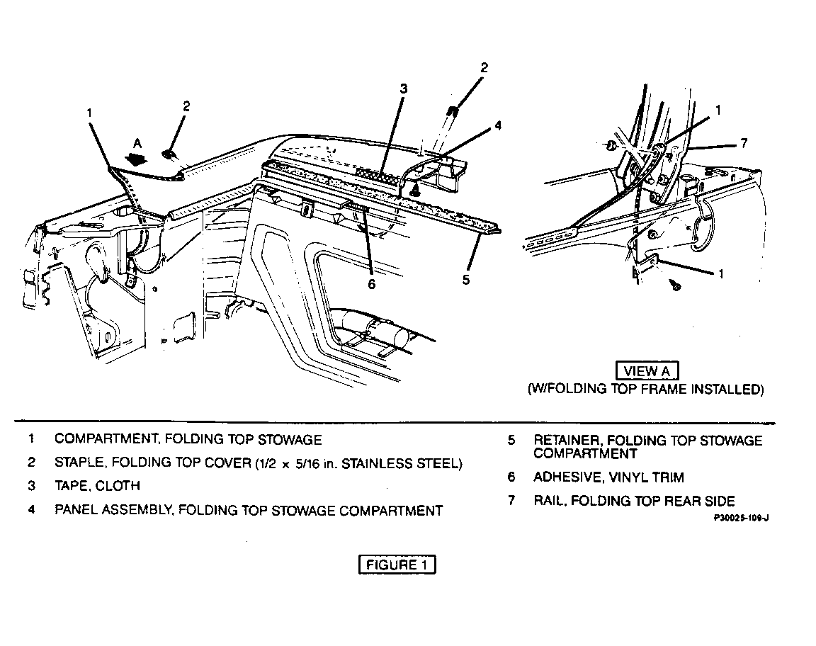
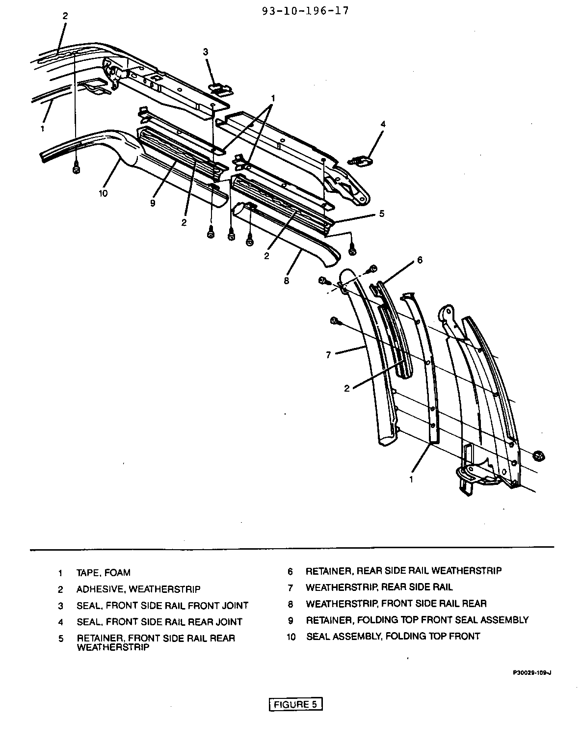
Figures 1, 2 and 3 Remove or Disconnect
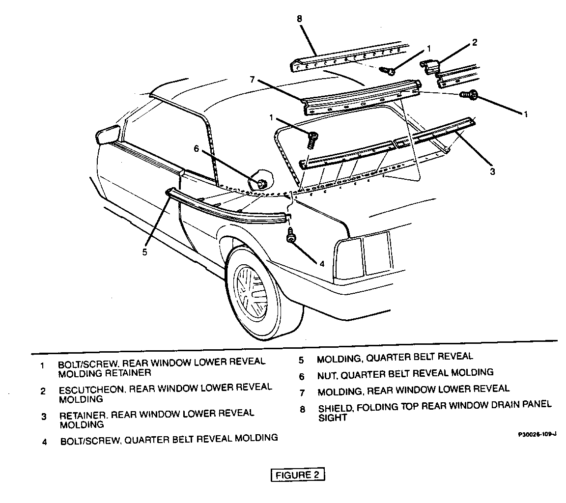
1. Rear seat cushion and seatback. Refer to Section 1 0-1 0 of the Service Manual. 2. LH quarter trim panel. Refer to Section 10-7 of the Service Manual. 3. Nuts securing LH upper comer of stowage compartment to LH rear side rail. 4. Nut and bolt securing LH lower comer of stowage compartment to quarter inner panel. 5. Peel LH portion of stowage compartment off quarter inner panel. 6. LH quarter belt reveal moulding nuts. 7. Screws securing rear window drain panel sight shield and remove shield. 8. Screws securing rear window lower reveal moulding and pull moldings away while sliding off of quarter belt reveal moldings. 9. Moulding retainer screws and moulding retainers. 10. LH quarter belt reveal moulding screw and pull moulding away from quarter panel to release studs of moulding from sheet metal. 11. Mark location of each sail panel on rear belt tack strip. Markings will aid in locating sail panels over tack strip during installation. 12. Release folding top front latches to relieve cover tension.
IMPORTANT: Remove only enough staples from RH sail panel as necessary to access staples retaining RH portion of window to tack strip. It is not necessary to remove staples retaining stowage compartment to tack strip.
13. Staples retaining LH sail panel and window to tack strip. Note location and spacing of staples. 14. Heated window connectors (if equipped). 15. Separate bottom edges of sail panel and window from butyl tape at tack strip. 16. Pull LH sail panel over cover to expose rivet or window upper retainer screw securing window to center of No.4 bow. 17. Drill out rivet using a 1/8 inch drill, or remove screw, then slide window out of No.4 bow by pulling on window from LH side of vehicle.
Install or Connect
1. Add butyl tape as necessary to tack strip to ensure complete sealing of window and sail panels to stowage compartment. 2. Position window at LH side of vehicle and feed bulb extrusion at top of window into slot in No.4 bow. 3. Align slot at top center of window with hole in No.4 bow and install either a 1/8 inch x 1/4 inch aluminum rivet or screw, whichever was removed. Tighten screw to 8 N.m (71 lbs. in.). 4. Position material at bottom of window over butyl tape on stowage compartment (at tack strip) and press into place. Have assistant support window from inside vehicle to prevent separation of window from tack strip. 5. Secure window to tack strip using 5/16 inch (width) by 1/2 inch (length) stainless steel staples. Apply downward pressure to material at each point of staple installation while working from center to each end of window. 6. Heated window connectors (if equipped). 7. Butyl tape at edges of window along tack strip where sail panels overlap window. 8. Pull sail panels down over butyl tape and into position with reference marks made during removal. Align holes for studs of quarter belt reveal moulding in sail panel with holes in tack strip. Press into place, keeping material flat without stretching. 9. Secure each sail panel to tack strip using 5/16 inch (width) by 1/2 inch (length) stainless steel staples. Install staples from rear to front of sail panel while applying downward pressure at each point. 10. Studs of LH quarter belt reveal moulding into sheet metal. Install screw and tighten securely. 11. Position moulding retainers over tack strip and align screw holes. Install screws and tighten securely. 12. Outer ends of lower reveal moldings over ends of quarter belt reveal moldings while engaging opposite ends together. Align screw holes, install screws and tighten securely. 13. Lower reveal moulding escutcheon. 14. Position sight shield over moldings and align screw holes. Install screws and tighten securely. 15. LH quarter belt reveal moulding nuts and tighten securely. 16. LH portion of stowage compartment to quarter inner panel using vinyl trim adhesive. 17. Nut and bolt retaining LH lower comer of stowage compartment to quarter inner panel and tighten securely. 18. Nut securing LH upper comer of stowage compartment to LH rear side rail and tighten securely. 19. LH quarter trim panel. 20. Rear seat cushion and seatback. 21. Lock top to windshield header, then check appearance of cover and window. Cover should be free from wrinkles and draws.
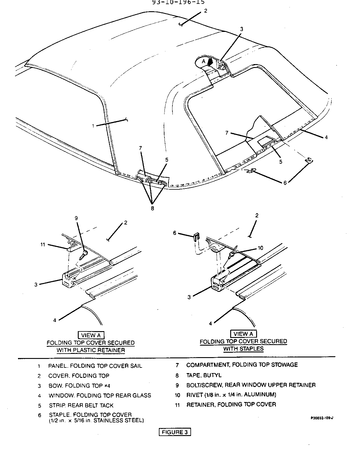
FOLDING TOP NO.4 BOW (WITH PLASTIC RETAINER)
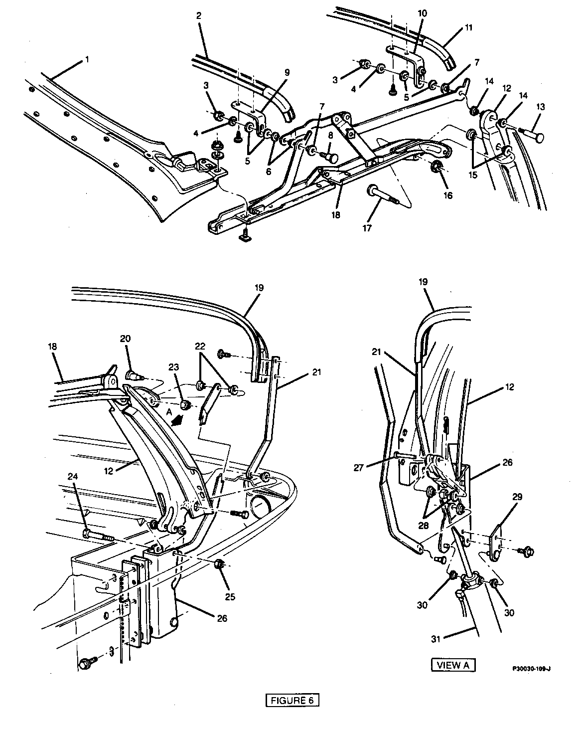
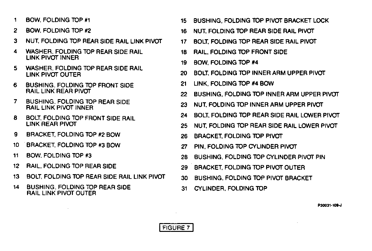
Figures 3 through 7 Remove or Disconnect
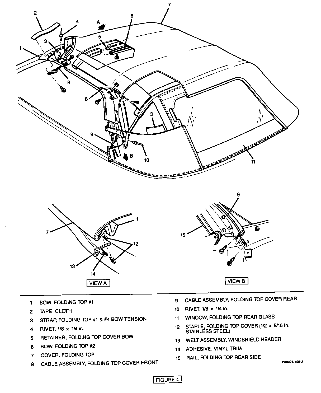
1. Raise top off windshield header to suitable working height and remove folding top front seal assembly. Refer to procedure in Section 10-9 of the Service Manual. 2. Front seal assembly retainer screws and separate LH and RH retainers from foam tape. 3. With top fully lowered, remove staples securing windshield header welt assembly and remove welt assembly from No.1 bow. 4. Screws securing retention cables to No.1 bow. Attach length of wire or string to end of each cable. This step will aid in pulling cables through cover if cable ends become trapped within material. 5. Staples securing folding top cover to No.1 bow, then peel cover from bow and front side rails. 6. Raise top to windshield header, remove screws securing folding top cover bow retainers to No.2 and No.3 bows, then remove retainers. 7. Screws and nuts securing LH and RH rear side rail weatherstrips and peel weatherstrips from retainers. 8. Rear side rail weatherstrip retainer screws and separate LH and RH retainers from foam tape. 9. Peel cover from rear side rails. 10. Bolts securing LH and RH No.4 bow links to rear side rails and remove bushings. 11. Screws securing No.4 bow link brackets to No.4 bow and remove link assembly.
IMPORTANT: Use care not to damage integral plastic locking mechanism or cover during removal of retainer.
12. Turn cover over to access No.4 bow. Using a hammer and a long narrow metal rod or wooden dowel, drive retainer out of No.4 bow. Note position of retainer during removal. 13. Carefully release locking mechanism from slot in No.4 bow. 14. Staples securing hook and loop strips covering No.1 and No.4 bow tension strap staples, then remove strips. 15. Staples securing tension straps to No.4 bow. Note location of straps on bow to aid in strap positioning during bow installation. 16. Window upper retainer screw and slide No.4 bow off window with help from an assistant.
Install or Connect
1. With help from an assistant, slide No.4 bow over bulb extrusion on window. Align hole in center of bow with hole in window and install retaining screw. Tighten screw to 8 N.m (71 lbs. in.). 2. Staple tension straps to No.4 bow at locations noted during removal using 5/16 inch (width) by 1/2 inch (length) stainless steel staples. Apply downward pressure to straps at each point of staple installation while working from center to each side. 3. Position hook and loop strip over tension straps and secure with staples. Strips prevent impressions of staples from appearing through cover. 4. Position retainer as noted during removal and insert into No.4 bow. 5. Position locking mechanism into slot of No.4 bow over retainer. Using a rubber mallet, seat entire length of locking mechanism into bow. 6. Position No.4 bow links (with rear side rail attachment facing forward) to No.4 bow, install screws and tighten securely. 7. Pull cover forward over frame assembly. 8. Bushings to No.4 bow links and position to rear side rails. Install bolts and tighten securely. 9. Attach cover to rear side rails with weatherstrip adhesive. 10. Attach LH and RH rear side rail weatherstrip retainers to rear side rails with foam tape. Install screws and tighten securely. 11. Attach LH and RH rear side rail weatherstrips to retainers with weatherstrip adhesive. Install screws and nuts and tighten securely. 12. Insert bow retainers through pockets in cover and secure with screws to No.2 and No.3 bows. Tighten screws securely. 13. Raise top to suitable working height over windshield header. Pull cover at seams straight forward over No. 1 bow to desired top fullness. While maintaining tension on cover, mark outer surface of cover along forward edge of No.1 bow. 14. Lower top and apply weatherstrip adhesive to cementing area of No.1 bow, front side rails and corresponding surfaces of cover and front comer flaps. Pull cover over No.1 bow, aligning mark on cover with forward edge of No.1 bow, and secure. 15. Staple cover to No.1 bow using 5/16 inch (width) by 1/2 inch (length) stainless steel staples. Apply downward pressure to material at each point of staple installation while working from center to each end of No.1 bow. 16. Raise top and lock to windshield header. Check operation and locking action of top. Inspect cover for proper appearance. If additional tension is needed in cover, remove staples and pull cover farther forward. Staple and recheck cover for proper appearance and operation. securely. 17. Remove string or wire attached to cables and position cable ends to No.1 bow. Install screws and tighten 18. Align windshield header welt assembly to No.1 bow. Fold vinyl flap over welt bulb and staple into position. 19. Apply weatherstrip adhesive to stapled edge of welt assembly and fold vinyl flap back over stapled surface. 20. Replace old foam tape with new foam tape and position front seal assembly retainer's to front side rail. Install screws and tighten securely. 21. Front seal assembly. Refer to the appropriate procedure in Section 1O-9 of the Service Manual.
FOLDING TOP NO.4 BOW (STAPLED)
Figures 3,4,6 and 7 Remove or Disconnect
1. Rear seat cushion and seatback. Refer to Section 10-10 of the Service Manual. 2. LH and RH quarter trim panels. Refer to Section 10-7 of the Service Manual. 3. Nuts securing upper corners of stowage compartment to LH and RH rear side rails. 4. Nuts and bolts securing lower comers of stowage compartment to quarter inner panels. 5. Peel LH and RH portions of stowage compartment off quarter inner panels. 6. LH and RH quarter belt reveal moulding nuts. 7. Screws securing rear window drain panel sight shield and remove shield. 8. Screws securing rear window lower reveal moulding and pull moldings away while sliding off of quarter belt reveal moldings. 9. Moulding retainer screws and lower reveal moulding retainers. 10. LH and RH quarter belt reveal moulding screws and pull moldings away from quarter panels to release studs of moldings from sheet metal. 11. Mark location of finished edge of each sail. panel on rear window at tack strip. Marks will aid in locating sail panels over tack strip during installation. 12. Release folding top front latches to relieve cover tension.
IMPORTANT: Only remove staples retaining sail panels to tack strip. It is not necessary to remove staples retaining stowage compartment
13. Staples retaining sail panels to tack strip. Note location and spacing of staples. 14. Separate bottom edge of each sail panel from butyl tape at tack strip. 15. Pull LH and RH sail panels over cover to expose No.4 bow. 16. Staples securing cover to tack strip of No.4 bow. Note location and spacing of staples. 17. Staples securing hook and loop strips covering No.1 and No.4 bow tension strap staples, then remove. 18. Staples securing tension straps to No.4 bow. Note location of straps on bow to aid in strap positioning during installation. 19. Screws securing No.4 bow to No.4 bow link brackets. 20. Drill out rivet retaining rear window to No.4 bow using a 1/8 inch drill, then slide bow off window with help from an assistant.
Install or Connect
1. With help from an assistant, slide No.4 bow over bulb extrusion on window. Align hole in center of bow with hole in window and install 1/8 inch x 1/4 inch aluminum rivet. 2. Position No.4 bow to brackets and install screws. Tighten screws to 19 N.m (14 lbs. ft.). 3. Staple Tension straps to No.4 bow at locations noted during removal using 5/16 inch (width) by 1/2 inch (length) stainless steel staples. Apply downward pressure to strap at each point of staple installation while working from center to each side. 4. Align stapling material of cover with rear edge of No.4 bow tack strip. Center cover over No.4 bow and secure material to bow using 5/16 inch (width) by 1/2 inch (length) stainless steel staples. Apply downward pressure to material at each point of staple installation while working from center to each side. 5. Position hook and loop strips over tension strap staples and secure with staples. Strips prevent impressions of staples from appearing through cover. 6. Add butyl tape as necessary to tack strip to ensure complete sealing of sail panels to stowage compartment and window. 7. Pull sail panels down over butyl tape and into position with marks made on rear window at tack strip. Align holes for studs of quarter belt reveal moldings in sail panels with holes in tack strip. Press into place, keeping material flat without stretching. 8. Secure each sail panel to tack strip using 5/16 inch (width) by 1/2 inch (length) stainless steel staples. Install staples from rear to front of sail panel while applying downward pressure at each point. 9. Studs of LH and RH quarter belt reveal moldings into sheet metal. Install screws and tighten securely. 10. Position moulding retainers over tack strip and align screw holes. Install screws and tighten securely. 11. Outer ends of lower reveal moldings over ends of quarter belt reveal moldings while engaging opposite ends together. Align screw holes, install screws and tighten securely. 12. Lower reveal moulding escutcheon. 13. Position sight shield over lower reveal moldings and align screw holes. Install screws and tighten securely. 14. LH and RH quarter belt reveal moulding nuts and tighten securely. 15. LH and RH portion of stowage compartment to quarter inner panels using vinyl trim adhesive. 16. Nuts and bolts retaining lower corners of stowage compartment to quarter inner panels and tighten securely. 17. Nut securing upper corners of stowage compartment to LH and RH rear side rails and tighten securely. 18. LH and RH quarter trim panels. 19. Rear seat cushion and seatback. 20. Lock top to windshield header, then check appearance of cover and window. Cover should be free from wrinkles and draws.
FOLDING TOP COVER
Figures 1 through 5 Remove or Disconnect
1. Rear seat cushion and seatback. Refer to Section 10-10 of the Service Manual. 2. LH and RH quarter trim panels. Refer to Section 10-7 of the Service Manual. 3. Nuts securing upper comers of stowage compartment to LH and RH rear side rails. 4. Nuts and bolts securing lower comers of stowage compartment to quarter inner panels. 5. Peel LH and RH portions of stowage compartment off quarter inner panels. 6. LH and RH quarter belt reveal moulding nuts. 7. Screws securing rear window drain panel sight shield and remove shield. 8. Screws securing rear window lower reveal moulding and pull moldings away while sliding off of quarter belt reveal moldings. 9. Moulding retainer screws and lower reveal moulding retainers. 10. LH and RH quarter belt reveal moulding screws and pull moldings away from quarter panels to release studs of moldings from sheet metal. 11. Using a sharp pencil, mark location of complete rear belt tack strip (upper edge) on outer surface of folding top cover. 12. Mark location of finished edge of each sail panel on rear window at tack strip. Marks will aid in locating sail panels over tack strip during installation. 13. Release folding top front latches to relieve cover tension.
IMPORTANT: Only remove staples retaining sail panels to tack strip. It is not necessary to remove staples retaining stowage compartment and window to tack strip.
14. Staples retaining sail panels to tack strip. Note location and spacing of staples. 15. Separate bottom edge of each sail panel from butyl tape at tack strip. 16. Pull LH and RH sail panels over cover to expose No.4 bow. 17. If cover is stapled to No.4 bow, remove staples securing cover while noting location and spacing of staples on tack strip of bow. 18. Mark location of all reveal moulding attaching holes on lower edge of tack strip or body. 19. Raise top off windshield header to suitable working height and remove folding top front seal assembly. Refer to the appropriate procedure in Section 10-9 of the Service Manual. 20. Front seal assembly retainer screws and separate LH and RH retainers from foam tape. 21. With top fully lowered, remove staples securing windshield header welt assembly and remove welt assembly from No.1 bow. 22. Screws securing retention cables to No.1 bow. If original cover is to be reinstalled, attach a length of wire or string to end of each cable. This step will aid in pulling cables through cover if cable ends become trapped within material. 23. Staples securing cover to No.1 bow, then peel cover from bow and front side rails to expose attachments to rail. 24. Raise top to windshield header, remove screws securing retainers to No.2 and No.3 bows and remove retainers. 25. Screws and nuts securing LH and RH rear side rail weatherstrips and peel weatherstrips from retainers. 26. Rear side rail weatherstrip retainer screws and separate LH and RH retainers from foam tape. 27. Screws securing cable ends to rear side rails. To ease removal of screws, raise top off windshield header. If replacing cover, pull cables through material using previously attached string or wire. 28. Peel cover from rear side rails. 29. If cover is secured to No.4 bow with integral plastic locking mechanism and wedged shaped retainer, fold cover back over rear compartment lid to access No.4 bow.
IMPORTANT: Use care not to damage locking mechanism, cover or window during removal of retainer.
30. Using a hammer and a long narrow metal rod or wooden dowel, drive retainer out of No.4 bow. Note position of retainer within bow during removal. 31. Carefully release locking mechanism from slot in No.4 bow and remove cover from vehicle.
Install or Connect
1. If replacing cover, transfer reference marks made on original cover to replacement cover as follows: a. Position replacement cover on a clean surface with exterior surface up. b. Position original cover over replacement cover. c. Carefully align rear window opening upper comers and quarter window upper corner's of both covers. d. Secure covers together at these locations. e. Carefully lay out sail panels of both covers. f. Transfer tack strip reference marks. g. Recheck location of reference marks. 2. Pull cables through replacement cover by attaching previously installed string or wire to a length of welding rod or other rigid material. Once cables have been pulled through cover material, disconnect welding rod. Leave string or wire attached to cable ends. 3. Add butyl tape as necessary to tack strip to ensure complete sealing of sail panels to stowage compartment. 4. If cover is secured to No.4 bow with plastic locking mechanism, follow Steps 5-11. If cover is stapled to No.4 bow, skip Steps 5-11 and proceed with Step 12. 5. Locking mechanism into slot in No.4 bow, if utilized. Do not install retainer at this time. 6. Position replacement cover over frame assembly and align finished edge of each sail panel with marks made on rear window at tack strip and press into place. If any draws or wrinkles are present after aligning sail panels, readjust cover at No.4 bow. 7. Secure sail panels to tack strip using 5/16 inch (width) by 1/2 inch (length) stainless steel staples. Apply downward pressure to material at each point of staple installation while working from rear to front of each sail panel. 8. Fold cover back over rear compartment lid to access No.4 bow.
IMPORTANT: Use care not to damage locking mechanism, cover or window during removal of retainer.
9. Carefully release locking mechanism from slot in No.4 bow. 10. Position cover retainer as noted during removal and insert into No.4 bow. 11. Position locking mechanism into slot of No.4 bow over retainer. Using a rubber mallet, seat entire length of locking mechanism into bow. 12. Position replacement cover over frame and align stapling material of cover with rear edge of No.4 bow tack strip. Center cover over No.4 bow and secure material to bow using 5/16 inch (width) by 1/2 inch (length) stainless steel staples. Apply downward pressure to material at each point of staple installation while working from center to each side. 13. Pull sail panels down over butyl tape and into position with marks made on rear window at tack strip. Align holes for studs of quarter belt reveal moldings in sail panel with holes in tack strip. Press sail panels into place, keeping material flat without stretching. . 14. Secure sail panels to tack strip using 5/16 inch (width) by 1/2 inch (length) stainless steel staples. Apply downward pressure to material at each point of staple installation while working from rear to front of each sail panel. 15. Attach cover to rear side rails with weatherstrip adhesive. 16. Attach LH and RH rear side rail weatherstrip retainers to rear side rails with foam tape. Install screws and tighten securely. 17. Attach LH and RH rear side rail weatherstrips to retainers with weatherstrip adhesive. Install screws and nuts and tighten securely. 18. Insert bow retainers through pockets in cover and secure with screws to No.2 and No.3 bows. Tighten screws securely. 19. Raise top to suitable working height over windshield header. Pull cover at seams straight forward over No. 1 bow to desired top fullness. While maintaining tension on cover, mark outer surface of cover along forward edge of No.1 bow. 20. Lower top and apply weatherstrip adhesive to cementing area of No.1 bow, front side rails and corresponding surfaces of cover and front comer flaps. Pull cover over No.1 bow, aligning mark on cover with forward edge of No.1 bow, and secure. 21. Staple cover to No.1 bow using 5/16 inch (width) by 1/2 inch (length) stainless steel staples. Apply downward pressure to material at each point of staple installation while working from center to each end of No.1 bow. 22. Raise top and lock to windshield header. Check operation and locking action of top. Inspect cover for proper appearance. If additional tension is needed in cover, remove staples and pull cover farther forward. Staple and recheck cover for proper appearance and operation. 23. Remove string or wire attached to cables and position cable ends to No. 1 bow. Install screws and tighten securely. 24. Align windshield header welt assembly to No. 1 bow. Fold vinyl flap over welt bulb and staple into position. 25. Apply weather strip adhesive to stapled edge of welt assembly and fold vinyl flap back over stapled surface. 26. Replace old foam tape with new foam tape and position front seal assembly retainer's to front side rails. Install screws and tighten securely. 27. Front seal assembly. Refer to the appropriate procedure in Section 10-9 of the Service Manual. 28. Studs of LH and RH quarter belt reveal moldings into sheet metal. Install screws and tighten securely. 29. Position moulding retainers over tack strip and align screw holes. Install screws and tighten securely. 30. Outer ends of lower reveal moldings over ends of quarter belt reveal moldings while engaging opposite ends together. Align screw holes, install screws and tighten securely. 31. Lower reveal moulding escutcheon. 32. Position sight shield over lower reveal moldings and align screw holes. Install screws and tighten securely. 33. LH and RH quarter belt reveal moulding nuts and tighten securely. 34. LH and RH portion of stowage compartment to quarter inner panels using vinyl trim adhesive. 35. Nuts and bolts retaining lower comers of stowage compartment to quarter inner panels and tighten securely. 36. Nut securing upper comers of stowage compartment to LH and RH rear side rails and tighten securely. 37. LH and RH quarter trim panels. 38. Rear seat cushion and seatback. 39. Lock top to windshield header, then check appearance of cover and window. Cover should be free from wrinkles and draws.
FOLDING TOP NO.4 BOW LINK
Figures 6 and 7 Remove or Disconnect
1. Screws securing No.4 bow to folding top No.4 bow link. 2. Bolt and bushing securing No.4 bow link to rear side rail.
Install or Connect
1. Bushing to No.4 bow link and position to rear side rail. Install bolt and tighten securely. 2. Position No.4 bow link (with rear side rail attachment facing forward) to No.4 bow. Install screws and tighten securely.
PARTS INFORMATION:
Cover, Folding Top-Complete, Retained to No. 4 Bow using a Plastic Retainer (Black) 12518385 (White) 12518386 Cover, Folding Top-Complete, Retained to No. 4 Bow using Staples: (Black) 12521924 (White) 12521925 Window, Folding Top Rear Glass 12518387 (Black) Non-Heated Window, Folding Top Rear Glass 12518388 (White) Non-Heated Window, Folding Top Rear Glass 12520363 (Black) Heated Window, Folding Top Rear Glass 12520364 (White) Heated Bow, Folding Top No.4 12518379 (Cover attached with plastic retainers) Bow, Folding Top No. 4 12521921 (Cover attached with staples) Link, Folding Top No.4 Bow 12518381
LABOUR OPERATION DESCRIPTION NUMBER LABOUR TIME ---------------------------- ------ ----------- Cover, Folding Top-Complete B3590 4.6 Hours Window, Folding Top Rear C0665 2.7 Hours Glass (Non-Heated) Window, Folding Top Rear C0665 2.9 Hours Glass (Heated) Bow, Folding Top No.4 B3340 4.1 Hours (cover stapled to bow) Bow, Folding Top No.4 B3340 3.0 Hours (cover snaps into bow) Link, Folding Top No.4 Bow B3345 0.3 Hour B3346 0.3 Hour
General Motors bulletins are intended for use by professional technicians, not a "do-it-yourselfer". They are written to inform those technicians of conditions that may occur on some vehicles, or to provide information that could assist in the proper service of a vehicle. Properly trained technicians have the equipment, tools, safety instructions and know-how to do a job properly and safely. If a condition is described, do not assume that the bulletin applies to your vehicle, or that your vehicle will have that condition. See a General Motors dealer servicing your brand of General Motors vehicle for information on whether your vehicle may benefit from the information.
