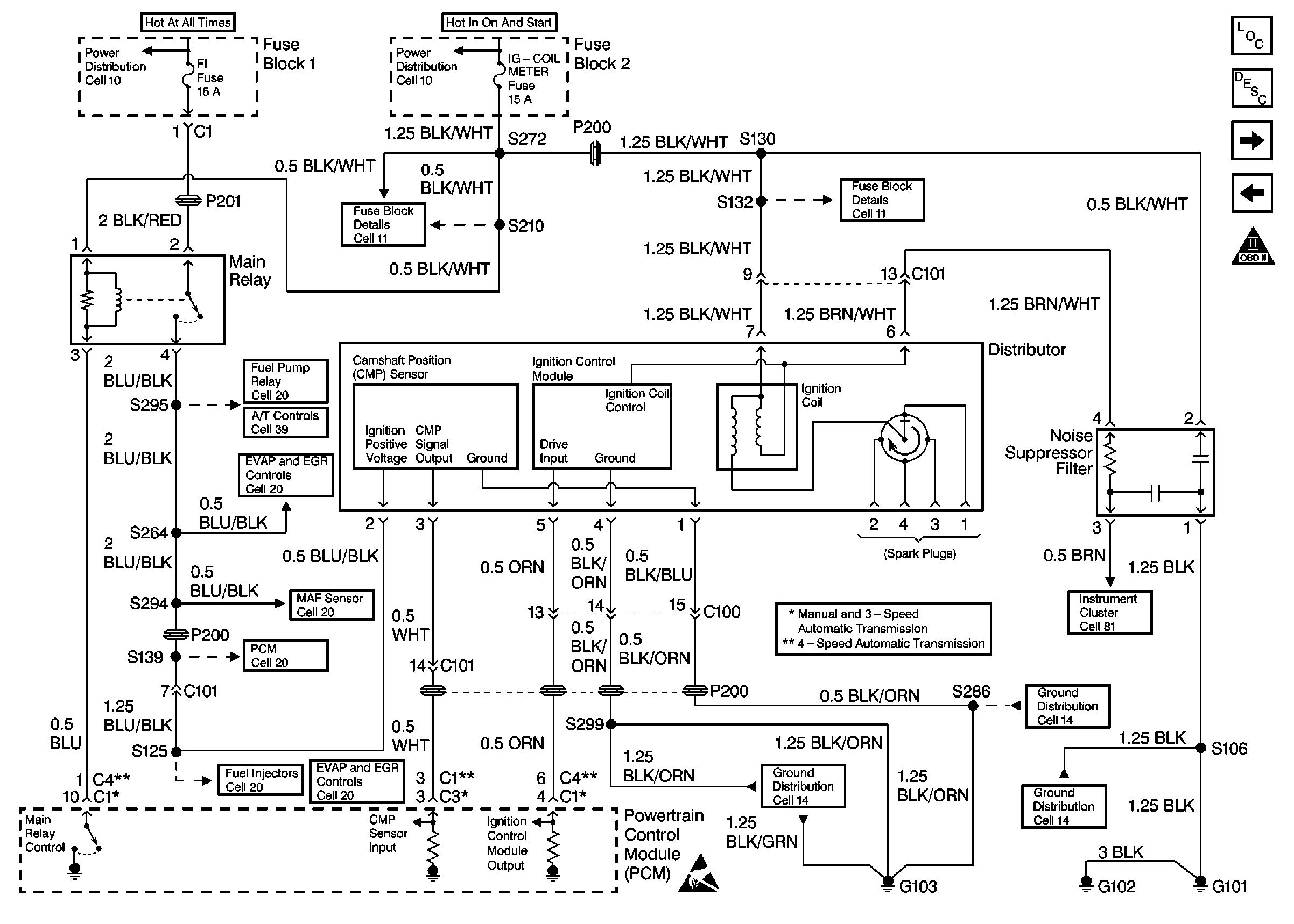
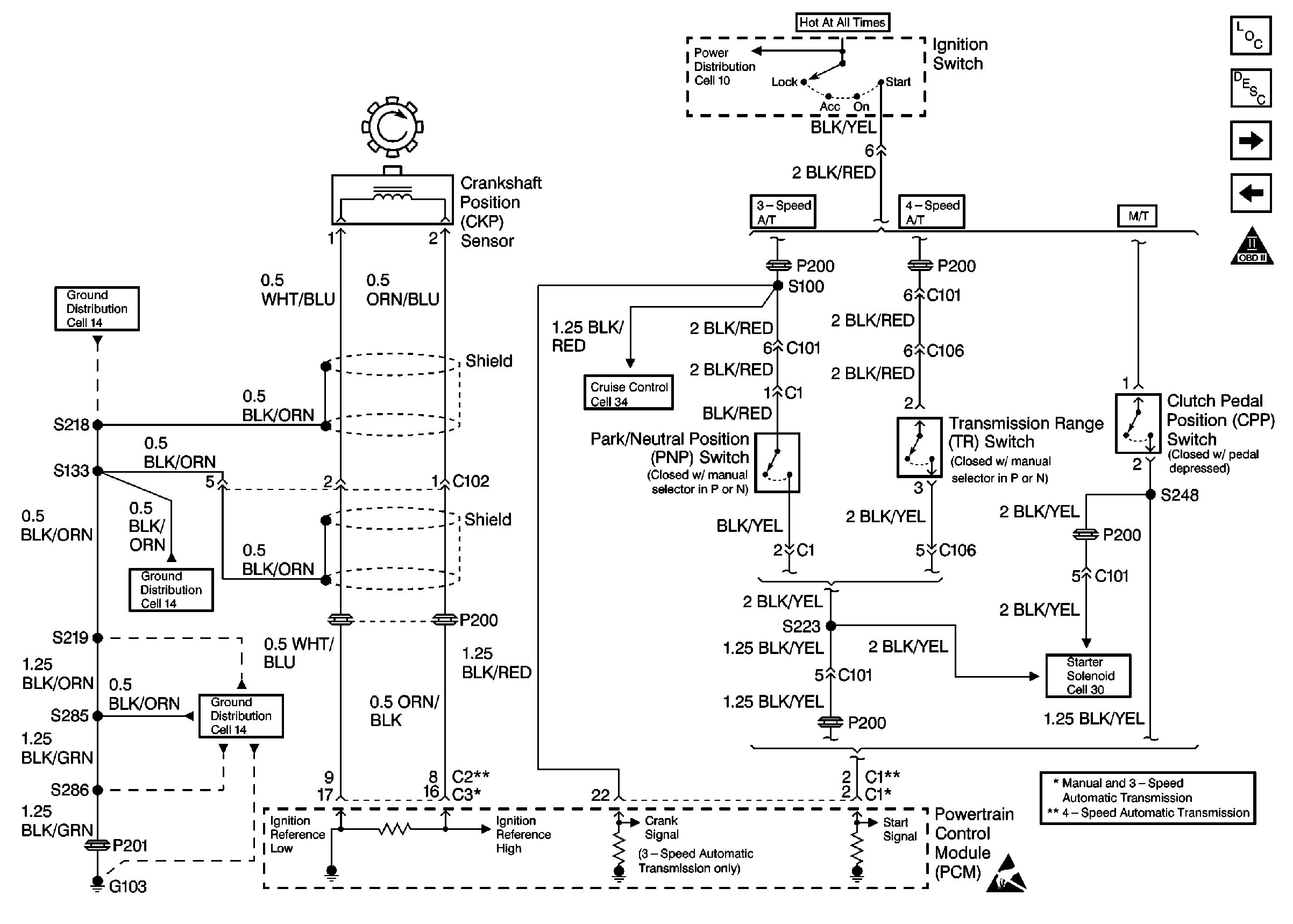
Refer to Engine Controls Schematics
Cell 20: Ignition System
and
Cell 20: CKP Sensor and Starter Signal
.
Circuit Description
The powertrain control module (PCM) uses information from the crankshaft position (CKP) sensor and the camshaft position (CMP) sensor in order to determine when an engine misfire is occurring. By monitoring changes in the crankshaft rotation for each cylinder the PCM counts individual misfire events. The malfunction indicator lamp (MIL) illuminates when the misfire rate equals or exceeds a pre-determined count. A misfire rate that is high enough can cause the catalytic converter to overheat under certain driving conditions. The MIL will flash On and Off when the conditions for catalytic converter overheating are present.
Conditions for Setting the DTC
| • | Engine coolant temperature greater than -7°C (19°F). |
| • | Intake air temperature is greater than -7°C (19°F). |
| • | Barometric pressure greater than 75 kPa. |
| • | Engine speed less than 4,000 RPM. |
| • | Fuel tank level greater than 15%. |
| • | TP sensor change is less than 1 degree / 10 ms. |
| • | Conditions present for 5 seconds after engine start to 1 second from fuel shut-off. |
Action Taken When the DTC Sets
| • | The PCM flashes the malfunction indicator lamp (MIL) the first time catalytic converter damage occurs. |
| • | The PCM illuminates the MIL the second time emission thresholds are exceeded (second time the diagnostic fails). |
| • | The PCM records the operating conditions at the time the diagnostic fails. This information is stored in the Freeze Frame buffer. |
Conditions for Clearing the MIL/DTC
| • | The MIL turns OFF after three consecutively passing trips without a fault present. |
| • | A History DTC clears after 40 consecutive warm-up cycles without a fault. |
| • | Use the scan tool Clear DTC Information function or disconnect the PCM battery feed in order to clear the DTC. |
Diagnostic Aids
Check for any of the following conditions:
| • | If any DTCs other than misfire (P0300 to P0304) are present, diagnose those DTCs first. |
| • | Check for engine overheating. |
| • | Check for engine vacuum leaks. |
| • | Improper EGR system operation. Refer to Exhaust Gas Recirculation (EGR) System Diagnosis . |
| • | A PCV system malfunction. Perform a functional check of the PCV valve. Refer to Crankcase Ventilation System Inspection . |
| • | Check for a malfunctioning fuel injector(s). Normal fuel injector resistance is 12-17 ohms at 20°C (68°F). Perform the Fuel Injector Coil Test/Balance Test Procedure if fuel injector resistance is out of specification. Refer to Fuel Injector Solenoid Coil Test - Engine Coolant Temperature Between 10-35 Degrees C (50-95 Degrees F) (50-95°F). |
| • | Fuel pressure that is out of specification. Refer to Fuel System Diagnosis . |
| • | An intermittent ignition system malfunction (spark plugs, ignition wires, ignition coil, and the distributor). Check ignition system performance with an engine oscilloscope. |
| • | An engine mechanical malfunction. Measure engine cylinder compression and valve lash adjustment for comparison to manufacture specifications. Refer to Engine Mechanical. |
| • | A damaged wiring harness. Inspect the applicable wiring harness for damage and repair as necessary. |
| • | A misfire DTC can also be the result of a defective crankshaft timing belt pulley. Remove the crankshaft position (CKP) sensor and inspect the crankshaft signal rotor through the sensor hole. Check the crankshaft timing belt pulley for foreign material or damaged teeth. |
If a DTC P0303 cannot be duplicated, the information included in the Freeze Frame data can be useful in determining vehicle operating conditions when the DTC was first set. When the fault can not be duplicated, wet the secondary ignition system of the suspect cylinder with water and operate the vehicle under the conditions that the DTC set.
Test Description
The numbers below refer to the step numbers in the Diagnostic Table.
-
The Powertrain (OBD) System Check prompts the technician to complete some basic checks and store the Freeze Frame data on the scan tool if applicable. This creates an electronic copy of the data taken when the fault occurred. The information is then stored in the scan tool for later reference.
-
This step verifies whether the misfire is present.
-
This step verifies whether the misfire is caused by a hard failure or an intermittent. A misfire can sometimes be cause by a rough road condition.
-
This step checks for the proper clearance of the signal rotor. The signal rotor should have enough clearance to not contact other components when rotating. The signal rotor clearance is not adjustable. A damaged or improperly aligned signal rotor will require component parts replacement.
-
Contaminants in the fuel, such as alcohol or water, may cause a misfire condition.
-
Low engine compression and improper lash may also cause a rough idling condition.
Step | Action | Value(s) | Yes | No | ||||||||||||||||||
|---|---|---|---|---|---|---|---|---|---|---|---|---|---|---|---|---|---|---|---|---|---|---|
Did you perform the Powertrain On-Board Diagnostic (OBD) System Check? | -- | |||||||||||||||||||||
Start the engine. Is a DTC P0303 present at idle? | -- | |||||||||||||||||||||
Does a DTC P0303 set? | -- | Go to Diagnostic Aids | ||||||||||||||||||||
4 |
Is an adequate spark present? | -- | ||||||||||||||||||||
5 |
Was a repair necessary? | -- | ||||||||||||||||||||
6 |
Did the #3 ignition wire need replacement? | 3.0k to 6.7k ohms/ft | ||||||||||||||||||||
7 |
Were any repairs necessary? | -- | ||||||||||||||||||||
Was a repair necessary? | -- | |||||||||||||||||||||
9 |
Did any spark plugs need replacement? | -- | ||||||||||||||||||||
10 |
Is the fuel pressure within the specified value? | 210-260 kPa (30-37 psi) | Go to Fuel System Diagnosis | |||||||||||||||||||
Check the fuel for contamination. Refer to Alcohol/Contaminants-in-Fuel Diagnosis . Is the fuel OK? | -- | |||||||||||||||||||||
12 | Replace the contaminated fuel. Is the action complete? | -- | -- | |||||||||||||||||||
13 |
Does the fuel injector test light blink? | -- | ||||||||||||||||||||
14 | Perform the Fuel Injector Coil Test/Balance Test Procedure. Refer to Fuel Injector Solenoid Coil Test - Engine Coolant Temperature Between 10-35 Degrees C (50-95 Degrees F) . Are the fuel injectors OK? | -- | ||||||||||||||||||||
15 |
Did the test light illuminate? | -- | ||||||||||||||||||||
16 |
Did the test light flash? | -- | Go to Diagnostic Aids | |||||||||||||||||||
17 | Replace the faulty fuel injector. Refer to Fuel Injector and Fuel Rail Replacement . Is the action complete? | -- | -- | |||||||||||||||||||
18 | Check the #3 fuel injector control circuit for any of the following conditions:
Was a problems found? | -- | ||||||||||||||||||||
19 | Repair the open or the short in the #3 fuel injector control circuit. Refer to Wiring Repairs in Wiring Systems. Is the action complete? | -- | -- | |||||||||||||||||||
20 | Repair the open in the ignition feed circuit between the fuel injector harness connector and the main relay. Refer to Wiring Repairs in Wiring Systems. Is the action complete? | -- | -- | |||||||||||||||||||
21 | Replace the PCM. Refer to Powertrain Control Module Replacement Is the action complete? | -- | -- | |||||||||||||||||||
Was a basic engine mechanical problem found and repaired? | -- | Go to Diagnostic Aids | ||||||||||||||||||||
23 |
Are any DTCs displayed on the scan tool? | -- | Go to the Applicable DTC Table | System OK |
