Refer to
Cell 20: Fuel Injectors
.
Circuit Description
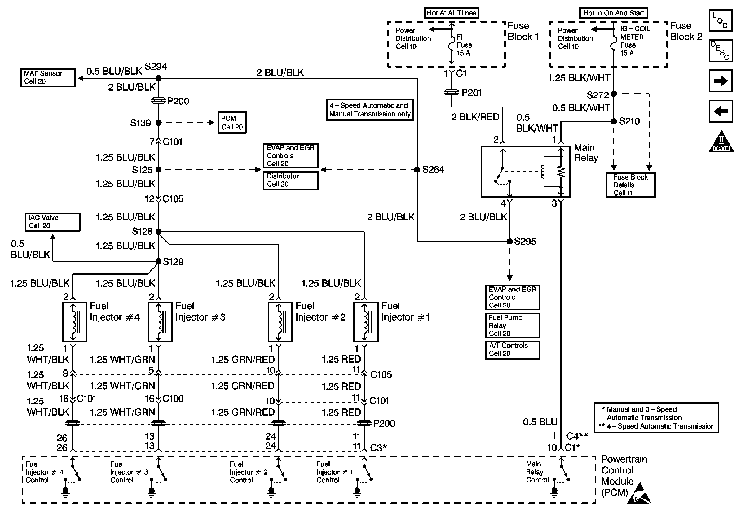
The powertrain control module (PCM) controls each individual fuel injector by providing a ground, this system is referred as Sequential Multiport Fuel Injection (SFI). When the ignition switch is turned to the on or start position (engine running), the PCM will energize/de-energize the fuel injector solenoid coil. With this coil energized, a plunger is activated, allowing pressurized fuel to be sprayed through the fuel injectors into the combustion chamber where it is mixed with air from the intake manifold; thus creating the proper air/fuel mixture needed for combustion.
Diagnostic Aids
Check for any of the following conditions:
| • | Water, foreign material, or stale fuel can cause a no start or a hard start condition. |
| • | Erratic fuel pressure or a restricted fuel filter may cause a no start or a hard start condition. |
| • | Faulty fuel injectors. There may be fuel spray at the fuel injectors, but it may not be enough to start the engine. Normal fuel injector resistance is 12-17 ohms at 20°C (68°F). If the fuel injectors and their circuits are OK, and fuel spray is detected, the fuel injector nozzle may be partly blocked or restricted. |
An intermittent malfunction may be caused by a fault in the fuel injector sensor circuit. Inspect the wiring harness and components for any of the following conditions:
| • | Backed out terminals. |
| • | Improper mating of terminals. |
| • | Broken electrical connector locks. |
| • | Improperly formed or damaged terminals. |
| • | Faulty terminal to wire connections. |
| • | Physical damage to the wiring harness. |
| • | A broken wire inside the insulation. |
| • | Corrosion of electrical connections, splices, or terminals. |
Test Description
The numbers below refer to the step numbers in the Diagnostic Table.
-
The Powertrain OBD System Check prompts the technician to complete some basic checks and store the freeze frame data on the scan tool if applicable. This creates an electronic copy of the data taken when the fault occurred. The information is then stored in the scan tool for later reference.
-
If a fuse is found to be the cause of the no start, locate and repair any shorts that may have caused the fuse to blow before replacing the fuse.
-
After one minute from the time the fuel pump stops running the fuel pressure should drop and hold to approximately 180 kpa (25 psi).
Step | Action | Value(s) | Yes | No | ||||||||||||||||
|---|---|---|---|---|---|---|---|---|---|---|---|---|---|---|---|---|---|---|---|---|
1 | Did you perform the Powertrain On-Board Diagnostic (OBD) System Check? | -- | ||||||||||||||||||
2 | Check the condition of the following items:
Do any of the above items require repair? | -- | ||||||||||||||||||
3 | Correct any faulty condition(s) found in Step 2. Is the action complete? | -- | -- | |||||||||||||||||
4 |
Important:: The fuel pump will run for about 3 seconds. To obtain maximum pressure it may be necessary to cycle the ignition ON to OFF to ON more than once.
Does the fuel pressure gauge read within the specified value? | 250-300 kPa (35-43 psi) | ||||||||||||||||||
5 |
Does the test light blink for each test? | -- | ||||||||||||||||||
6 |
Did any fuel injector(s) need replacing? | -- | ||||||||||||||||||
7 |
Was a problem found and corrected? | -- | ||||||||||||||||||
8 | Did the fuel injector test light stay ON steady for one or more fuel injectors? | -- | ||||||||||||||||||
9 |
Was a repair necessary? | -- | ||||||||||||||||||
10 |
Does the DMM read the specified voltage for each test? | B+ | ||||||||||||||||||
11 |
Does the test light blink for each test? | -- | Go to Diagnostic Aids | |||||||||||||||||
12 |
Is the action complete? | -- | -- | |||||||||||||||||
13 |
Was a repair necessary? | -- | ||||||||||||||||||
14 | Replace the PCM. Refer to Powertrain Control Module Replacement . Is the action complete? | -- | -- | |||||||||||||||||
15 | Inspect and repair the engine mechanical problem. Refer to Engine Mechanical to diagnose and repair any of the following conditions:
Is the action complete? | -- | Go To Diagnostic Aids | |||||||||||||||||
16 |
Does the engine start and continue to run? | -- | ||||||||||||||||||
17 |
Are any DTCs displayed? | -- | Go to the applicable DTC table | System OK |
