For 1990-2009 cars only
Removal Procedure
- Remove the front tire and wheel assembly as needed. Refer to Tire and Wheel Removal and Installation.
- Remove the rack and pinion boot. Refer to Rack and Pinion Boot Replacement.
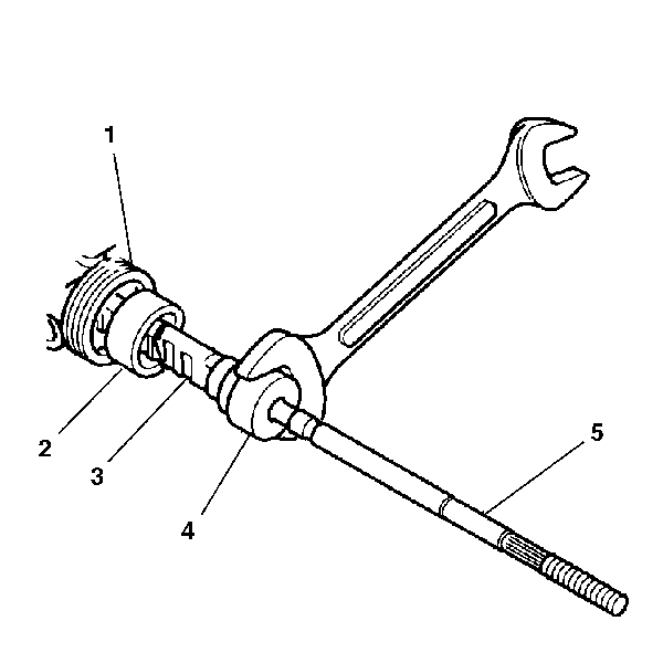
- Slide the shock dampener (2) back onto the rack (1).
- Remove the steering linkage inner tie rod (5) from the rack assembly (1) as follows:
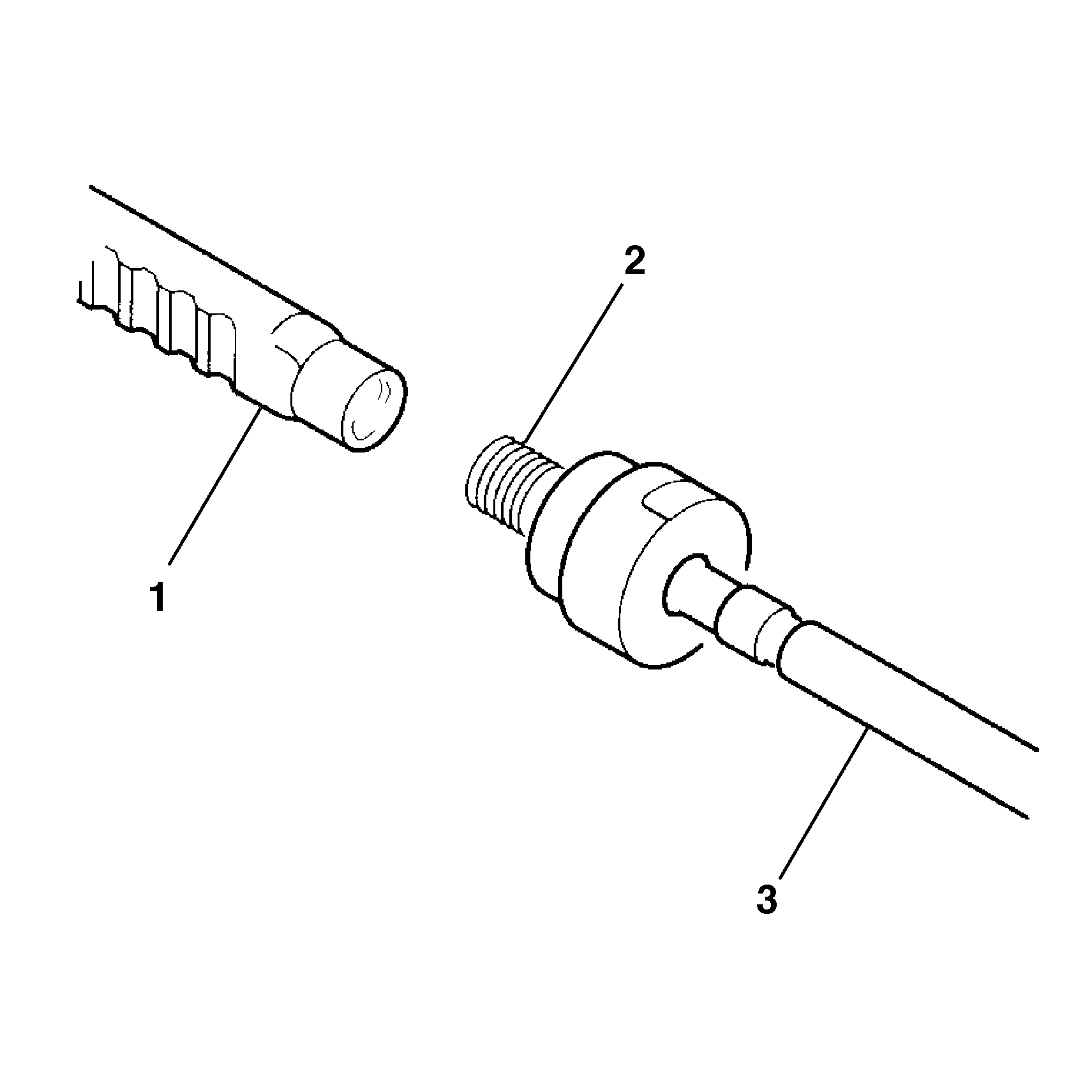
- Remove the old LOCTITE® from the threads (2) of the rack (1) and the steering linkage inner tie rod (3).
Note: After removing the boot, inspect the inner tie rod for evidence of corrosion or contamination. If none is evident, continue with the repair. If corrosion or contamination is evident, replace the steering gear.

Note: Hold the steering rack while removing the inner tie rod by placing a wrench on the flats of the gear teeth.
| 4.1. | Hold the gear by placing a wrench on the flats of the gear teeth (3). |
| 4.2. | Place a wrench on the flats of the steering linkage inner tie rod housing (4). |
| 4.3. | Rotate the steering linkage inner tie rod housing (4) counterclockwise until the steering linkage inner tie rod (5) separates from the rack. |

Installation Procedure
- Apply LOCTITE® 262 (or equivalent) to the steering linkage inner tie rod threads (2).
- Install the steering linkage inner tie rod (3) to the rack (1).
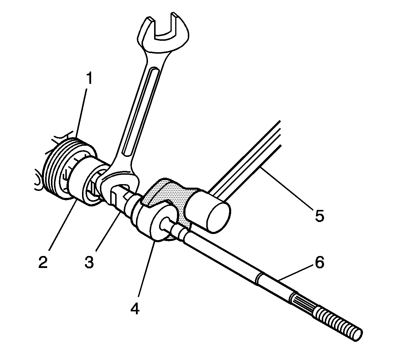
- Install a torque wrench (5) to the appropriate size crows foot to tighten the steering linkage inner tie rod (6).
- Slide the shock dampener (2) over the steering linkage inner tie rod housing (4) until the front lip of the shock dampener bottoms out against the inner tie rod housing.
- Install the rack and pinion boot. Refer to Rack and Pinion Boot Replacement.
- Install the tire and wheel assembly to the vehicle. Refer to Tire and Wheel Removal and Installation.
- Adjust the front toe. Refer to Front Toe Adjustment.

Note: Make sure the shock dampener is on the rack before installing the inner tie rod.
The threads must be clean prior to the LOCTITE® application. Check the LOCTITE® (or equivalent) container for expiration date. Use only enough LOCTITE® to evenly coat the threads.Caution: Refer to Fastener Caution in the Preface section.

Hold the flats of the gear teeth (3) while tightening the steering linkage inner tie rod housing (4) to 80 N·m (60 lb ft) as shown.
