Tools Required
| • | J 42129 Wheel Hub Remover |
| • | J 44394 Seal Protector |
Removal Procedure
Important: In the following service procedure the left side is shown, the right side is similar.
- Raise and support the vehicle. Refer to Lifting and Jacking the Vehicle .
- Remove the tire and wheel assembly. Refer to Tire and Wheel Removal and Installation .
- Remove the rear brake rotor. Refer to Rear Brake Rotor Replacement .
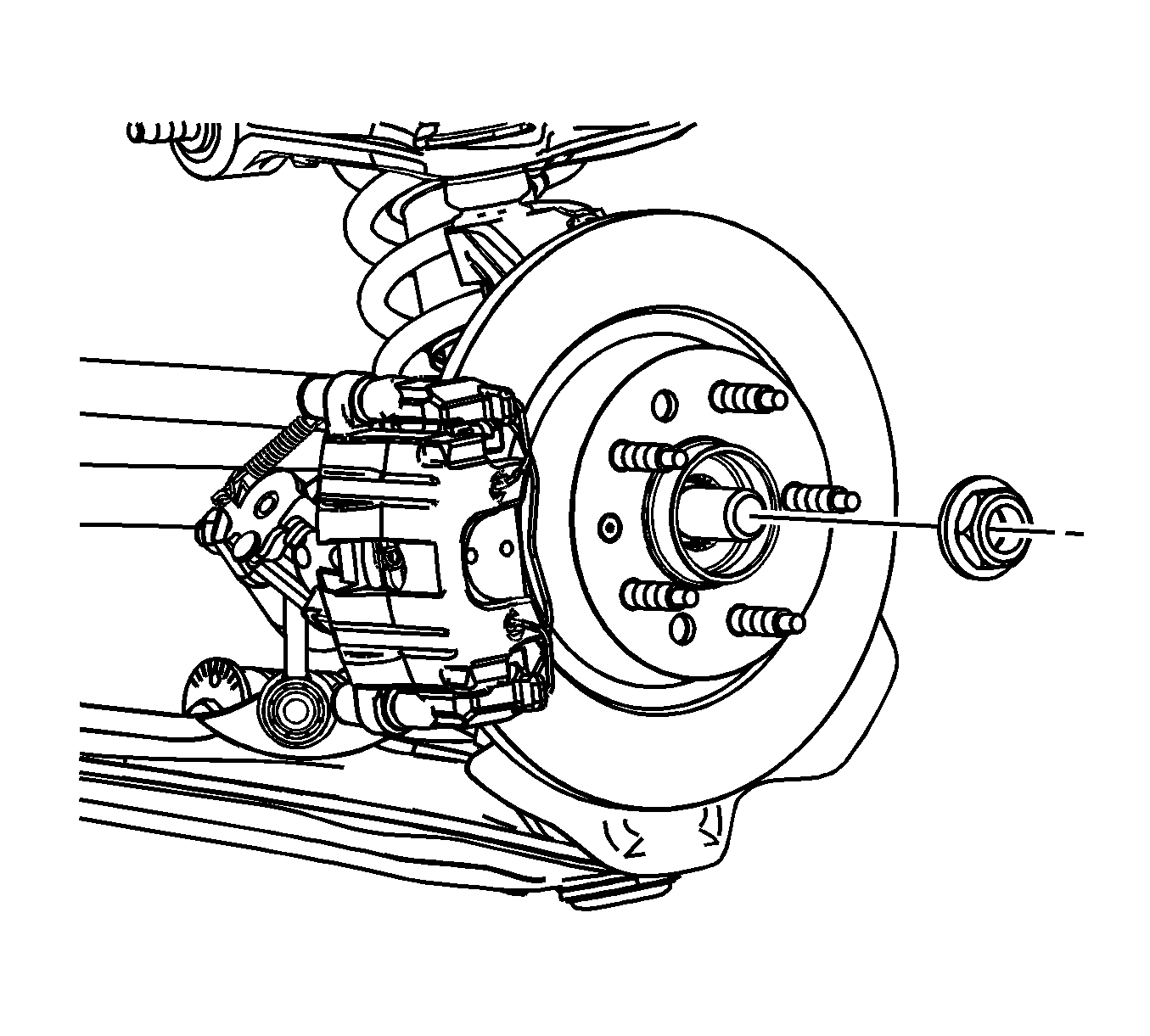
- Remove and discard the wheel drive shaft spindle nut.
- Using J 42129 , CJ129 Universal Hub Puller - Snap-On, 7394 Universal Hub Puller - OTC, or equivalent, disengage the wheel drive shaft from the wheel bearing/hub.
- Remove the adjustment link. Refer to Adjust Link Replacement .
- Separate the upper ball joint from the rear knuckle. Refer to Knuckle Replacement .
- Using a suitable tool, carefully release the wheel drive shaft from the rear differential enough to install the J 44394 .
- Carefully install the J 44394 over the wheel drive shaft.
- Carefully slide the J 44394 into the differential output shaft seal.
- Remove the wheel drive shaft from the vehicle.
- If reusing the wheel drive shaft, remove and discard the wheel drive shaft retaining ring. The wheel drive shaft retaining ring is on the splined shaft of the cross groove joint.
Important: The wheel drive shaft spindle nut must not be reused. Replace the wheel drive shaft spindle nut with a new nut whenever it is removed.
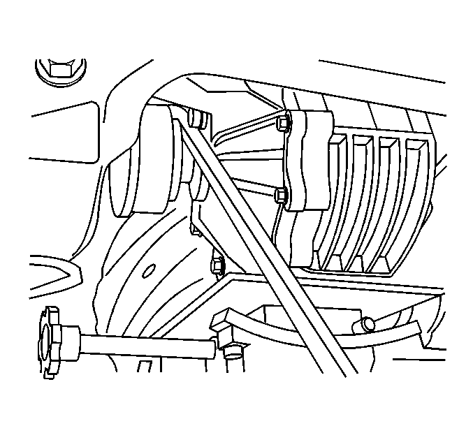
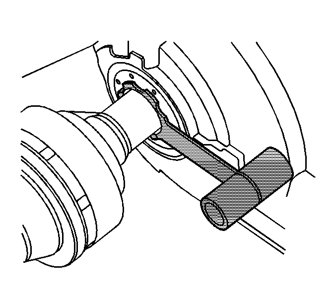
Notice: J-44394 must be installed into the differential output shaft seal prior to removing and installing the wheel drive shaft. Failure to install J-44394 as indicated may cause the splines of the wheel drive shaft to cut the differential output seal.
Installation Procedure
- Install the new wheel drive shaft retaining ring. The wheel drive shaft retaining ring is on the splined shaft of the cross groove joint.
- If previously removed, carefully install J 44394 into the differential output shaft seal.
- Carefully install the wheel drive shaft into the differential until the splines are past the J 44394 . Ensure that the retaining ring is installed in the upright position.
- Carefully remove the J 44394 from the differential output shaft seal.
- Carefully remove J 44394 from the wheel drive shaft.
- Carefully install the wheel drive shaft into the differential until the retaining ring is engaged.
- Ensure the wheel drive shaft retaining ring is fully engaged to the differential by grasping the inner housing and pulling outward. The wheel drive shaft will stay positively engaged if properly installed to the differential.
- Install the upper ball joint to the rear knuckle. Refer to Knuckle Replacement .
- Loosely install the NEW wheel drive shaft spindle nut.
- Install the adjustment link. Refer to Adjust Link Replacement .
- Use the new wheel drive shaft spindle nut to slowly pull the spindle to the wheel hub and bearing assembly.
- Install the rear brake rotor. Refer to Rear Brake Rotor Replacement .
- Install the tire and wheel assembly. Refer to Tire and Wheel Removal and Installation .
- Inspect the differential lubricant level. Refer to Rear Axle Lubricant Level Inspection .
- Lower the vehicle.
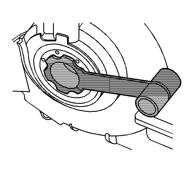
Notice: J-44394 must be installed into the differential output shaft seal prior to removing and installing the wheel drive shaft. Failure to install J-44394 as indicated may cause the splines of the wheel drive shaft to cut the differential output seal.
Important: In order to prevent lubricant leaks, use care when installing the wheel drive shaft to the differential. Do not damage the oil seal. Replace the oil seal if it becomes nicked, distorted, or is otherwise damaged.

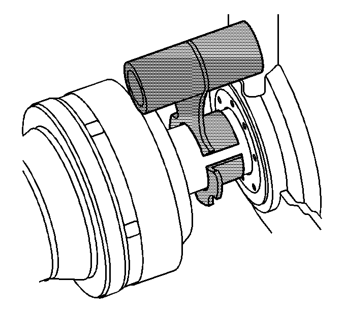

Important: Ensure that the drive shaft seals do not have any abrasions, cuts or punctures.
Notice: Refer to Fastener Notice in the Preface section.

Tighten
Tighten the wheel drive shaft spindle nut to 215 N·m (159 lb ft).
