Diagnostic Instructions
| • | Perform the Diagnostic System Check - Vehicle prior to using this diagnostic procedure. |
| • | Review Strategy Based Diagnosis for an overview of the diagnostic approach. |
| • | Diagnostic Procedure Instructions provides an overview of each diagnostic category. |
DTC Descriptors
DTC B1259 00: Antenna Ground Circuit MalfunctionDiagnostic Fault Information
Circuit | Short to Ground | Open/High Resistance | Short to Voltage | Signal Performance |
|---|---|---|---|---|
Left Audio Signal (+) | 1 | 1 | 1 | -- |
Right Audio Signal (+) | 2 | 2 | 2 | -- |
Audio Common (-) | 2 | 2 | 2 | -- |
Digital Radio Antenna Coax | 3 | 3 | 3 | -- |
1. No or distorted audio from left side speakers when listening to digital radio 2. No or distorted audio from right side speakers when listening to digital radio 3. Poor or no digital radio reception | ||||
Circuit/System Description
The digital radio receiver (DRR) receives XM satellite radio signals via a digital radio antenna located on the outside of the vehicle. The signal is passed to the DRR through digital radio antenna coax. From the DRR, separate left and right audio signals (+) are sent to the radio. The radio processes these signals and passes the audio to the appropriate speakers or audio amplifier.
Conditions for Running the DTC
| • | Radio ON. |
| • | Battery voltage must be between 9-16 volts. |
Conditions for Setting the DTC
The DTC will set when the DRR detects a short to voltage, short to ground, or an open/high resistance in the antenna ground circuit.
Actions Taken When the DTC Sets
| • | Digital radio reception may be poor or not available. |
| • | The radio displays "No XM Signal" or "Check Antenna". |
Conditions for Clearing the DTC
| • | The condition responsible for setting the DTC no longer exists. |
| • | A history DTC will clear once 100 consecutive malfunction-free ignition cycles have occurred. |
Reference Information
Schematic Reference
Radio/Navigation System Schematics
Connector End View Reference
Entertainment/Communication Connector End Views
Description and Operation
Radio/Audio System Description and Operation
Electrical Information Reference
Scan Tool Reference
Control Module References for scan tool information
Special Tools
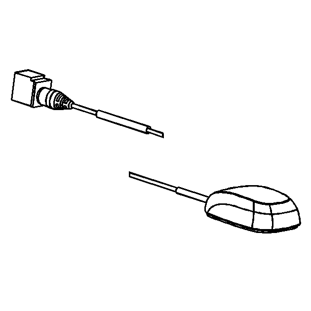
EL-48028 Digital Radio Test Antenna
Circuit/System Testing
Important:
• Ensure the vehicle is outside in an area with an unobstructed view of the southern sky. Turn XM radio ON. Tune the radio to satellite channel 1. XM reception should be clear. • Contact XM radio services at 1-800-852-9696 to verify the customers account status or possible network problems.
- Ignition OFF, disconnect the digital radio antenna coax from the digital radio receiver (DRR). Connect the EL-48028 to the DRR.
- Ignition ON, radio tuned to XM, verify XM reception is clear and uninterrupted.
- Ignition OFF, disconnect the digital radio antenna coax from the digital radio antenna.
- Ignition ON, test for less than 1 volt between the antenna coax center terminal and ground.
- Test for infinite resistance between the antenna coax center terminal and ground.
- Test for less than 5 ohms on the antenna coax center circuit from end to end.
- Test for less than 5 ohms between the two ends of the coax cable outer shield.
- Test for infinite resistance between the coax center terminal and the outer shield.
- If all circuits test normal, replace the digital radio antenna.
| ⇒ | If reception is not clear, replace the DRR. |
| ⇒ | If greater than the specified range, replace the antenna coax. |
| ⇒ | If less than the specified value, replace the antenna coax. |
| ⇒ | If greater than the specified range, replace the antenna coax. |
| ⇒ | If greater than the specified range, replace the antenna coax able. |
| ⇒ | If less than the specified value, replace the antenna coax. |
Repair Instructions
Perform the Diagnostic Repair Verification after completing the diagnostic procedure.
| • | Control Module References for DRR replacement, setup, and programming |
