Callous
| Component Name
|
|
Notice: Secure the steering wheel utilizing a strap to prevent rotation. Locking of the steering column will prevent damage and a possible malfunction of the SIR system. The steering wheel must be secured
in position before disconnecting the following components:
After disconnecting these components, do not move the front tires and wheels. Failure to follow these procedures may cause improper alignment of some components during installation and result in possible damage to the SIR coil.
Preliminary Procedures
- Remove the driver knee bolster bracket. Refer to
Driver Knee Bolster Bracket Replacement.
- If equiped, remove the clutch pedal assembly. Refer to
Clutch Pedal Replacement.
- Remove the steering wheel. Refer to
Steering Wheel Replacement.
- Remove the steering column trim covers. Refer to
Steering Column Trim Cover Replacement.
|
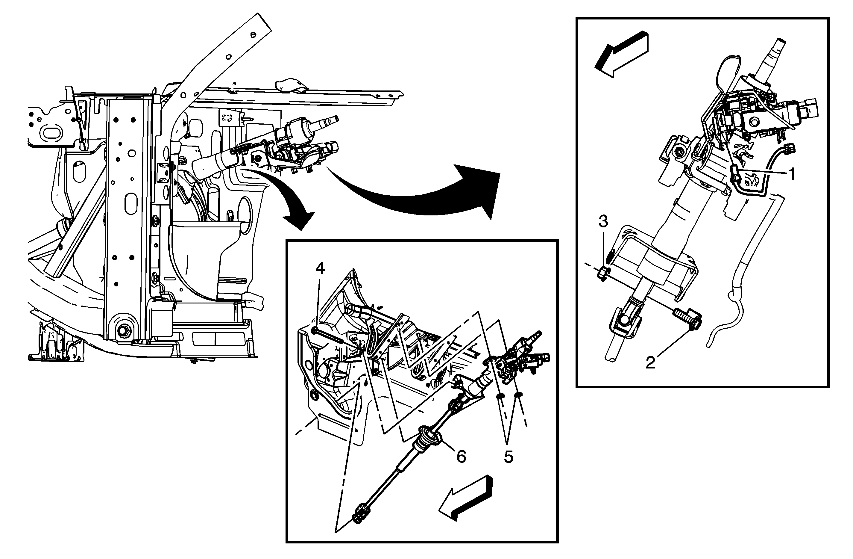
1
| Ignition/Start Switch Electrical Connector
|
2
| Intermediate Steering Shaft Bolt
Notice: Refer to Fastener Notice in the Preface section.
Tip
Discard the bolt.
Tighten
58 N·m (43 lb ft) |
3
| Intermediate Steering Shaft Nut
Tighten
58 N·m (43 lb ft) |
4
| Steering Column Lower Support Bracket Bolt
Tighten
25 N·m (18 lb ft) |
5
| Steering Column Upper Support Bracket Nut (Qty: 2)
Tighten
25 N·m (18 lb ft) |
6
| Steering Column
Procedure
- Disconnect all electrical connectors as needed.
- Transfer any parts as needed.
|
Callous
| Component Name
|
|
Notice: Secure the steering wheel utilizing a strap to prevent rotation. Locking of the steering column will prevent damage and a possible malfunction of the SIR system. The steering wheel must be secured
in position before disconnecting the following components:
After disconnecting these components, do not move the front tires and wheels. Failure to follow these procedures may cause improper alignment of some components during installation and result in possible damage to the SIR coil.
Preliminary Procedures
- Remove the driver knee bolster bracket. Refer to
Driver Knee Bolster Bracket Replacement.
- Remove the steering wheel. Refer to
Steering Wheel Replacement.
- Remove the steering column trim covers. Refer to
Steering Column Trim Cover Replacement.
|
1
| Ignition/Start Switch Electrical Connector
|
2
| Intermediate Steering Shaft Bolt
Notice: Refer to Fastener Notice in the Preface section.
Tip
Discard the bolt.
Tighten
58 N·m (43 lb ft) |
3
| Intermediate Steering Shaft Nut
Tighten
58 N·m (43 lb ft) |
4
| Steering Column Lower Support Bracket Bolt
Tighten
25 N·m (18 lb ft) |
5
| Steering Column Upper Support Bracket Nut (Qty: 2)
Tighten
25 N·m (18 lb ft) |
6
| Steering Column
Procedure
- Disconnect all electrical connectors as needed.
- Transfer any parts as needed.
|


