For 1990-2009 cars only
Stabilizer Shaft Replacement FE5

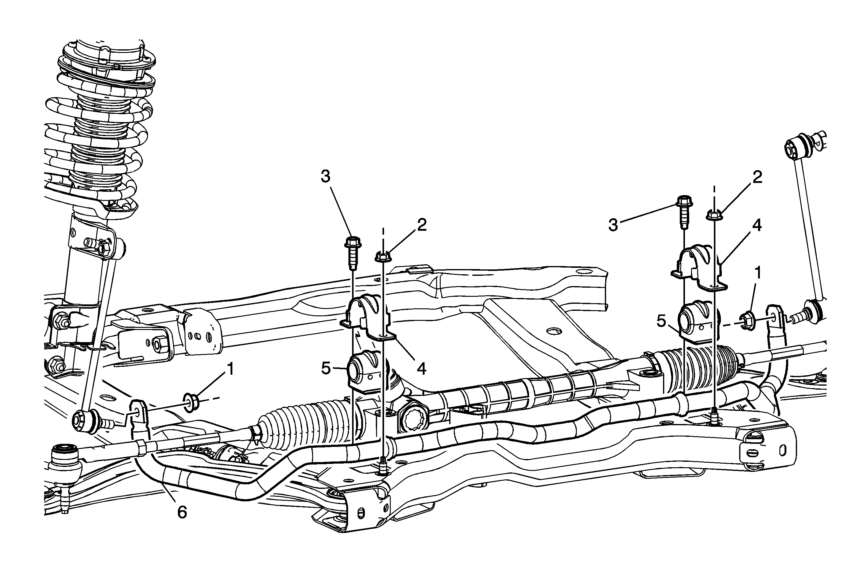
Callout | Component Name |
|---|---|
|
Notice: Refer to Fastener Notice in the Preface section. Fastener Tightening Specifications: Refer to Fastener Tightening Specifications . Preliminary Procedures
| |
1 | Front Stabilizer Shaft Link Lower Nut (Qty: 2) Tip Tighten |
2 | Front Stabilizer Shaft Clamp Nut (Qty: 2) Tighten |
3 | Front Stabilizer Shaft Clamp Bolt (Qty: 2) Tighten |
4 | Front Stabilizer Shaft Clamp |
5 | Front Stabilizer Shaft Insulator Tip |
6 | Front Stabilizer Shaft Tip |
Stabilizer Shaft Replacement FE1/FE3
Removal Procedure
- Raise and support the vehicle. Refer to Lifting and Jacking the Vehicle.
- Remove the front wheels. Refer to Tire and Wheel Removal and Installation .
- Remove the rear transaxle mount. Refer to Transmission Rear Mount Replacement for the Getrag 5 Speed transmission, or Transmission Rear Mount Replacement for the MU3 transmission, or Transmission Rear Mount Replacement for the 4T40-E/4T45-E transaxle.
- Remove the steering gear. Refer to Steering Gear Replacement.
- Disconnect the stabilizer links from the stabilizer shaft. Refer to Stabilizer Shaft Link Replacement .
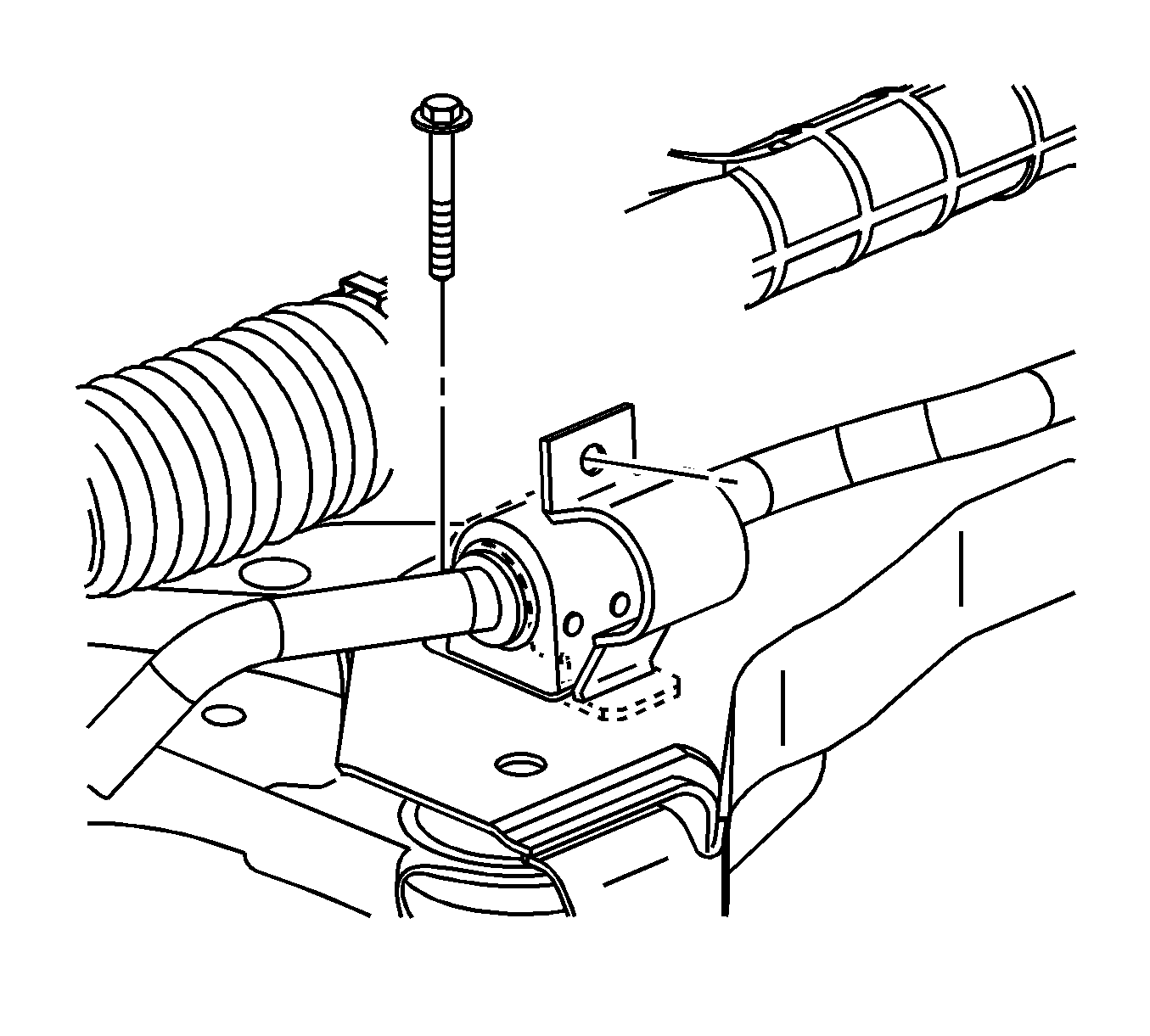
- Remove the stabilizer bar mounting clamp bolts and clamps from both sides of the vehicle.
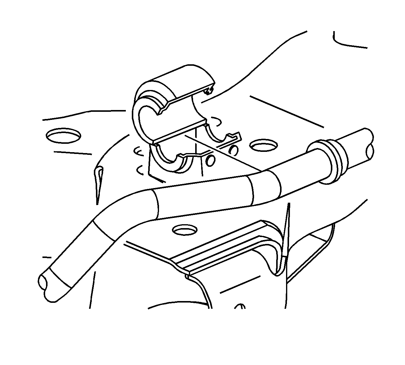
- Remove the bushings from the stabilizer bar.
- Lift and rotate the stabilizer bar up and to the right.
- Carefully remove the stabilizer bar from the right side of the vehicle.


Installation Procedure
- Move the stabilizer bar into position from the right side of the vehicle.
- Install the stabilizer bushings on the stabilizer bar with the cut line facing rearward.
- Install the stabilizer bar clamps and bolts.
- Connect the stabilizer links to the stabilizer shaft. Refer to Stabilizer Shaft Link Replacement .
- Install the steering gear. Refer to Steering Gear Replacement.
- Install the rear transaxle mount. Refer to Transmission Rear Mount Replacement for the Getrag 5 Speed transmission, or Transmission Rear Mount Replacement for the MU3 transmission, or Transmission Rear Mount Replacement for the 4T40-E/4T45-E transaxle.
- Install the front wheels. Refer to Tire and Wheel Removal and Installation.
- Lower the vehicle.

Notice: Refer to Fastener Notice in the Preface section.

Tighten
Tighten the bolts to 50 N·m (37 lb ft).
