GM Service Manual Online
For 1990-2009 cars only
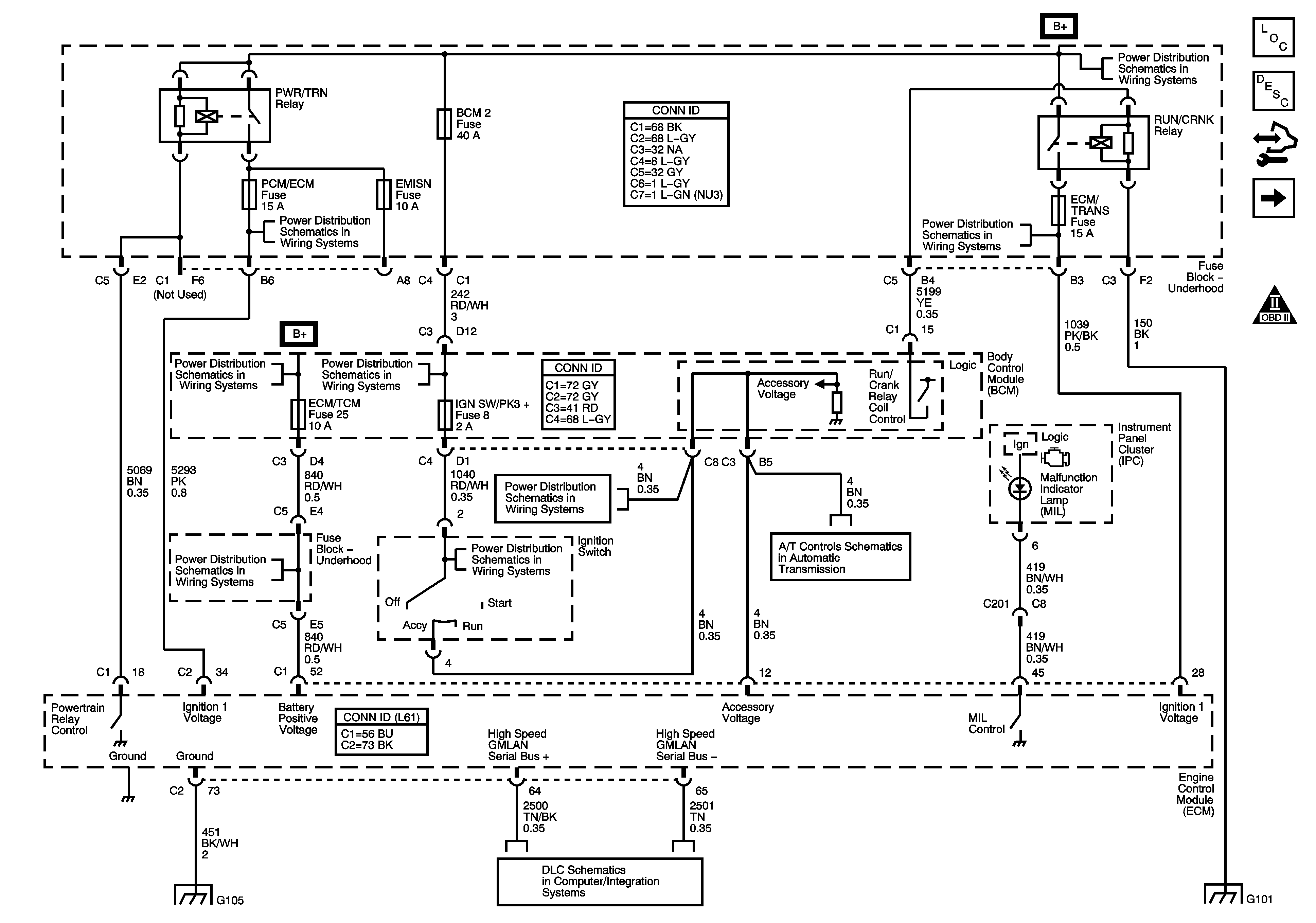
Figure 1:

Power, Ground, MIL, and DLC


Object Number: 1582618  Size: FS
Master Electrical Component List
Engine Control Module Description
Control Module References
Engine Data Sensors - 5-Volt and Low Reference Bussing
Engine Controls Schematic Icons
FUEL PUMP, POWERTRAIN Relay, FUEL PUMP, EMISSION, INJECTOR Fuses
BCM2, CLUSTER, IGN SW, STOP LPS, AUDIO AMPLIFIER Fuses
Underhood Fuse Block, B+ Bus
RUN/CRANK Relay, I/P IGN, BACKUP, ABS, ECM, TRANS, LIGHTING, S-BAND, MIRROR, ABS, EPS, BCM2, BCM3, HEATED SEATS Fuses
BCM2, CLUSTER, IGN SW, STOP LPS, AUDIO AMPLIFIER Fuses
TCM, Power, Ground, and PNP Switch
G103, G105
High Speed GMLAN
G101, G102
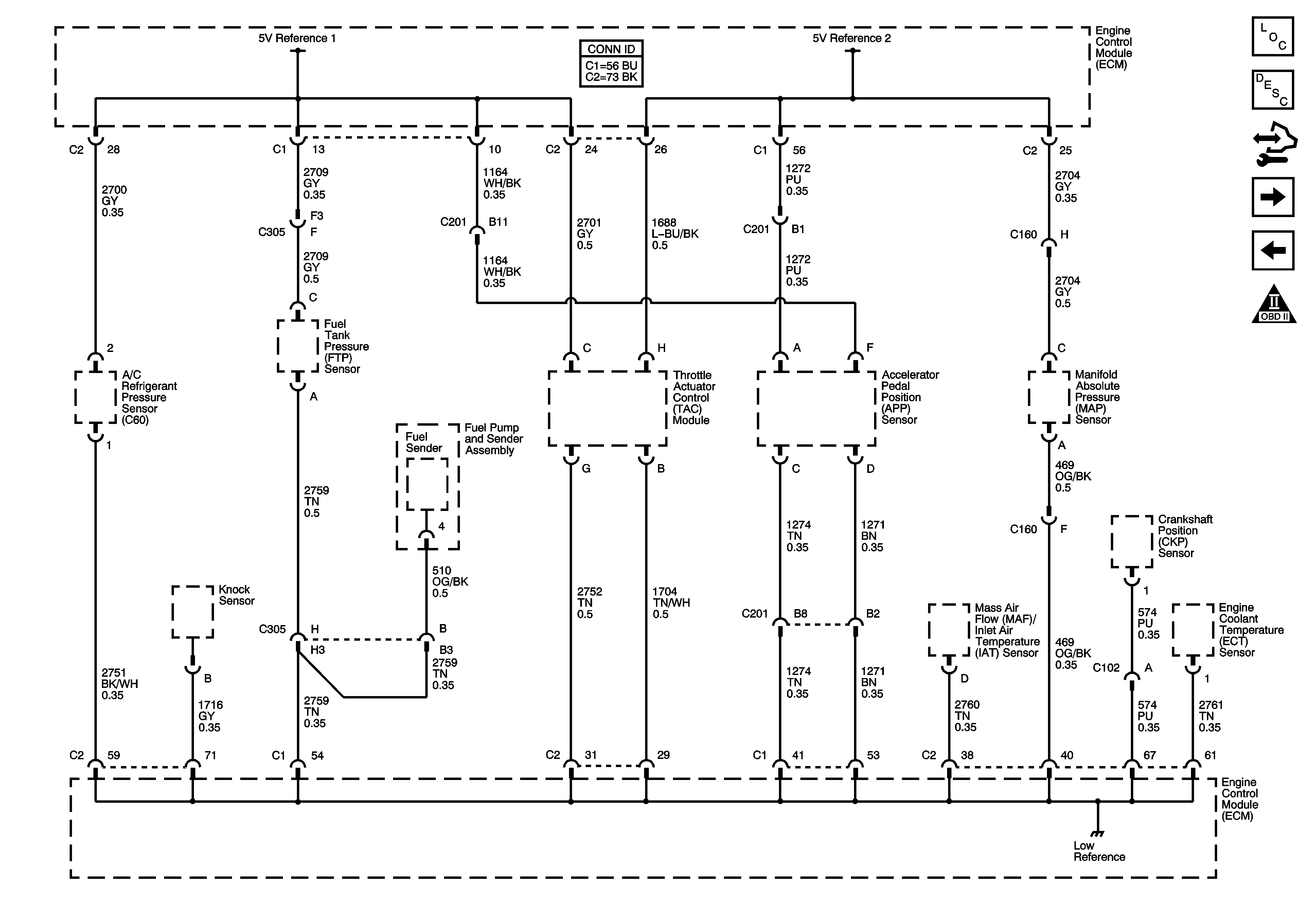
Figure 2:

Engine Data Sensors - 5-Volt and Reference Bussing

Object Number: 1582619  Size: FS
Master Electrical Component List
Engine Control Module Description
Control Module References
Engine Data Sensors - Pressure, Temperature, and MAF/IAT
Power, Ground, MIL, and DLC
Engine Controls Schematic Icons
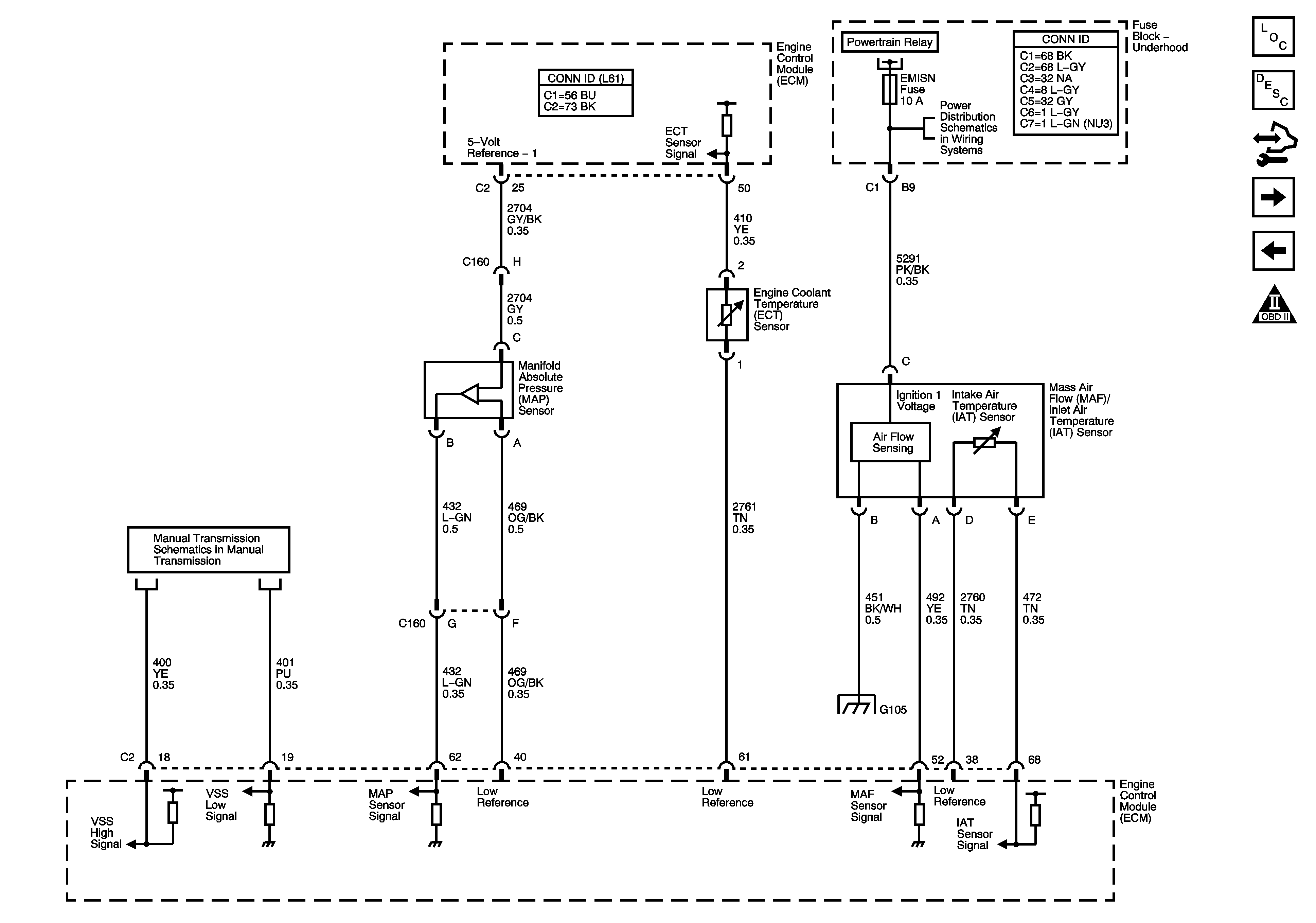
Figure 3:

Engine Data Sensors - Pressure, Temperature, and MAF/IAT


Object Number: 1582622  Size: FS
Master Electrical Component List
Secondary Air Injection System Description
Control Module References
Engine Data Sensors, HO2S
Engine Data Sensors - 5-Volt and Low Reference Bussing
Engine Controls Schematic Icons
FUEL PUMP, POWERTRAIN Relay, FUEL PUMP, EMISSION, INJECTOR Fuses
Manual Transmission (L61/2.2L) Schematics
G103, G105
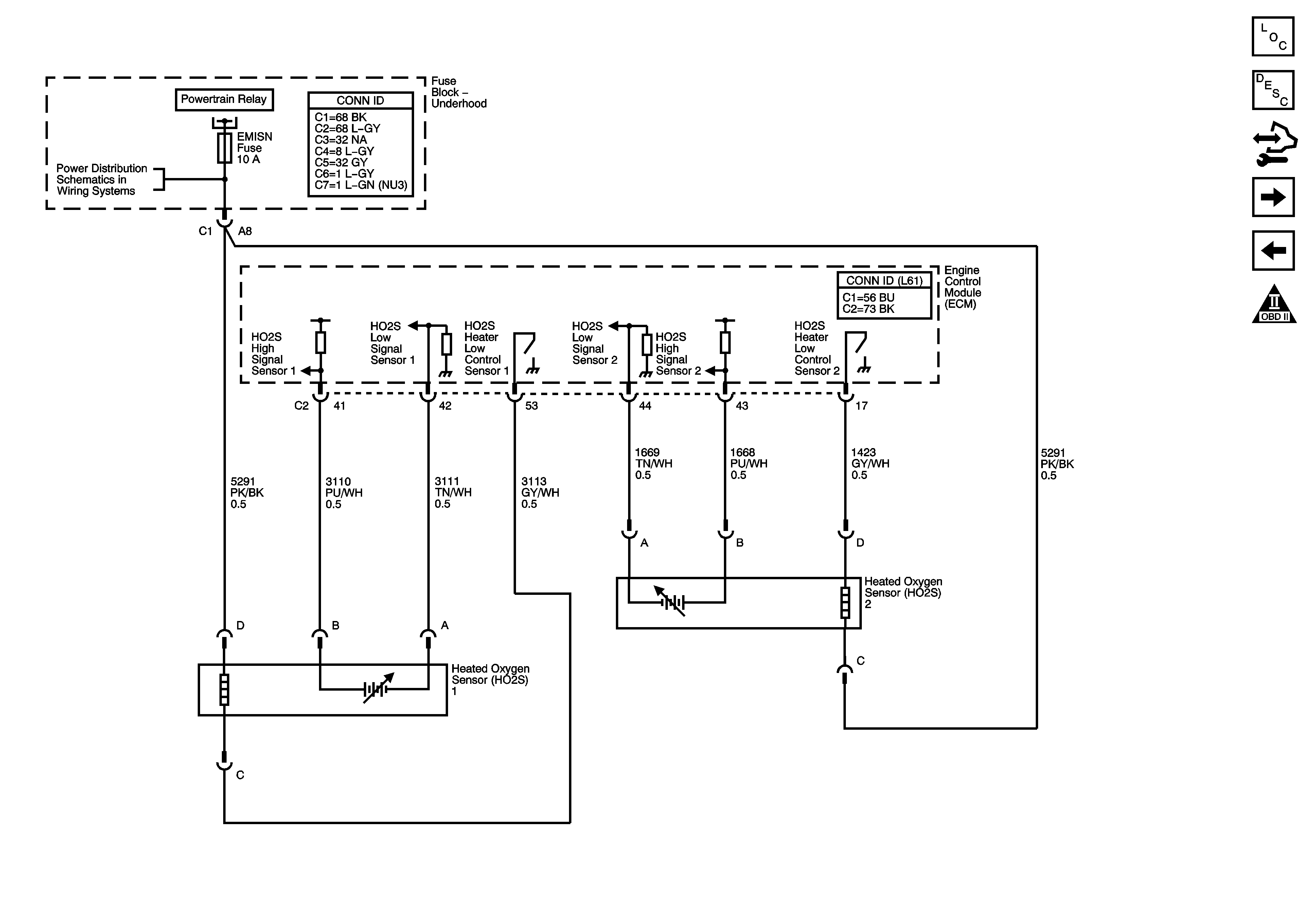
Figure 4:

Engine Data Sensors, HO2S


Object Number: 1582623  Size: FS
Master Electrical Component List
Engine Control Module Description
Control Module References
Engine Data Sensors, APP and TAC
Engine Data Sensors - Pressure, Temperature, and MAF/IAT
Engine Controls Schematic Icons
FUEL PUMP, POWERTRAIN Relay, FUEL PUMP, EMISSION, INJECTOR Fuses
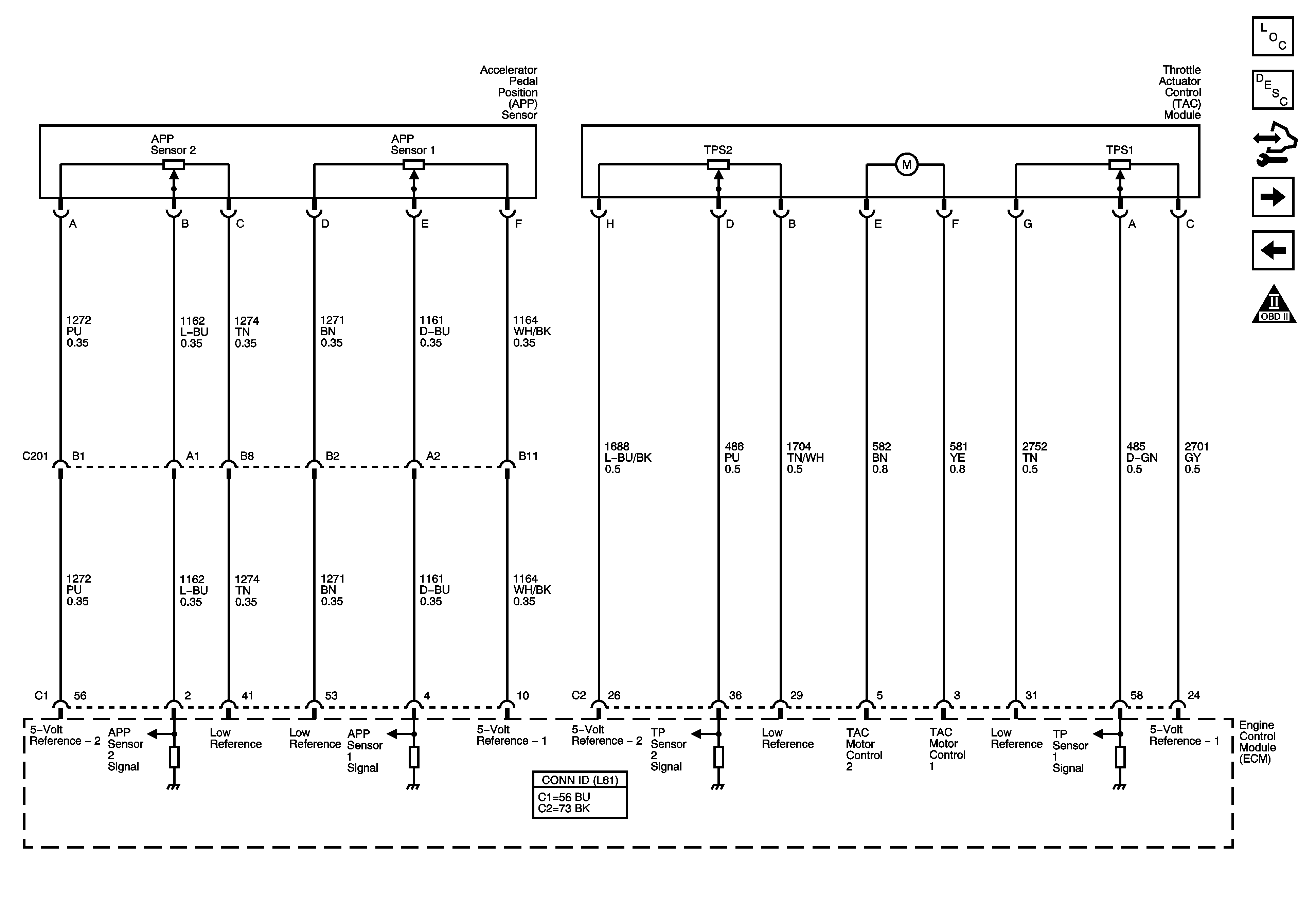
Figure 5:

Engine Data Sensors, APP and TAC


Object Number: 1582628  Size: FS
Master Electrical Component List
Throttle Actuator Control (TAC) System Description
Control Module References
Ignition Controls - Ignition System and Sensors
Engine Data Sensors, HO2S
Engine Controls Schematic Icons
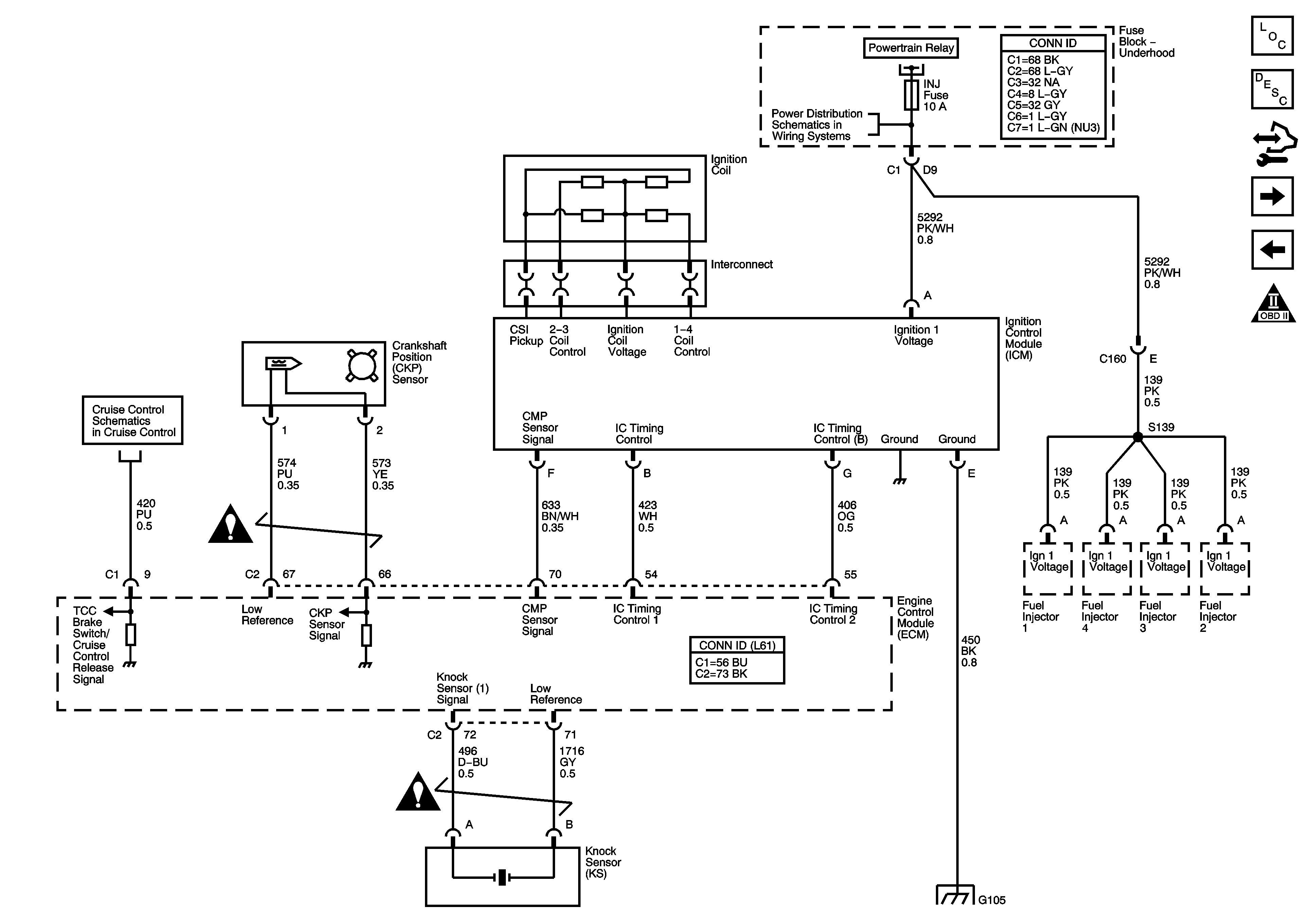
Figure 6:

Ignition Controls, Ignition System, and Sensors

Object Number: 1582632  Size: FS
Master Electrical Component List
Electronic Ignition (EI) System Description
Control Module References
Fuel Controls and Injectors
Engine Data Sensors, APP and TAC
Engine Controls Schematic Icons
FUEL PUMP, POWERTRAIN Relay, FUEL PUMP, EMISSION, INJECTOR Fuses
Clutch Pedal Position Switch, Stop Lamp Switch
Engine Controls Schematic Icons
G103, G105
Figure 7:

Secondary Air Injection (AIR) System (NU3)
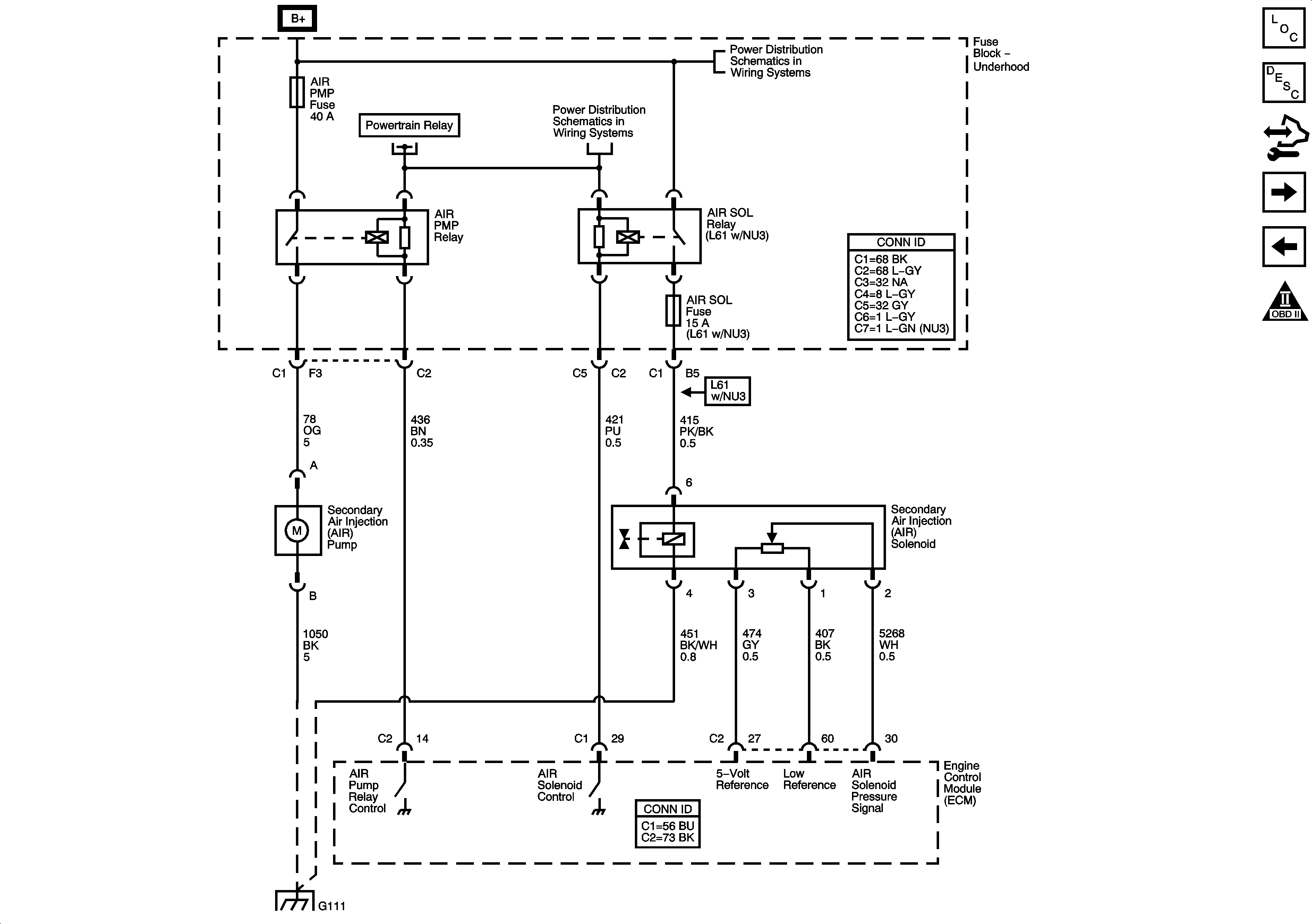

Object Number: 1700452  Size: FS
Master Electrical Component List
Engine Control Module Description
Control Module References
Fuel Controls and Injectors
Ignition Controls - Ignition System and Sensors
Engine Controls Schematic Icons
Underhood Fuse Block, B+ Bus
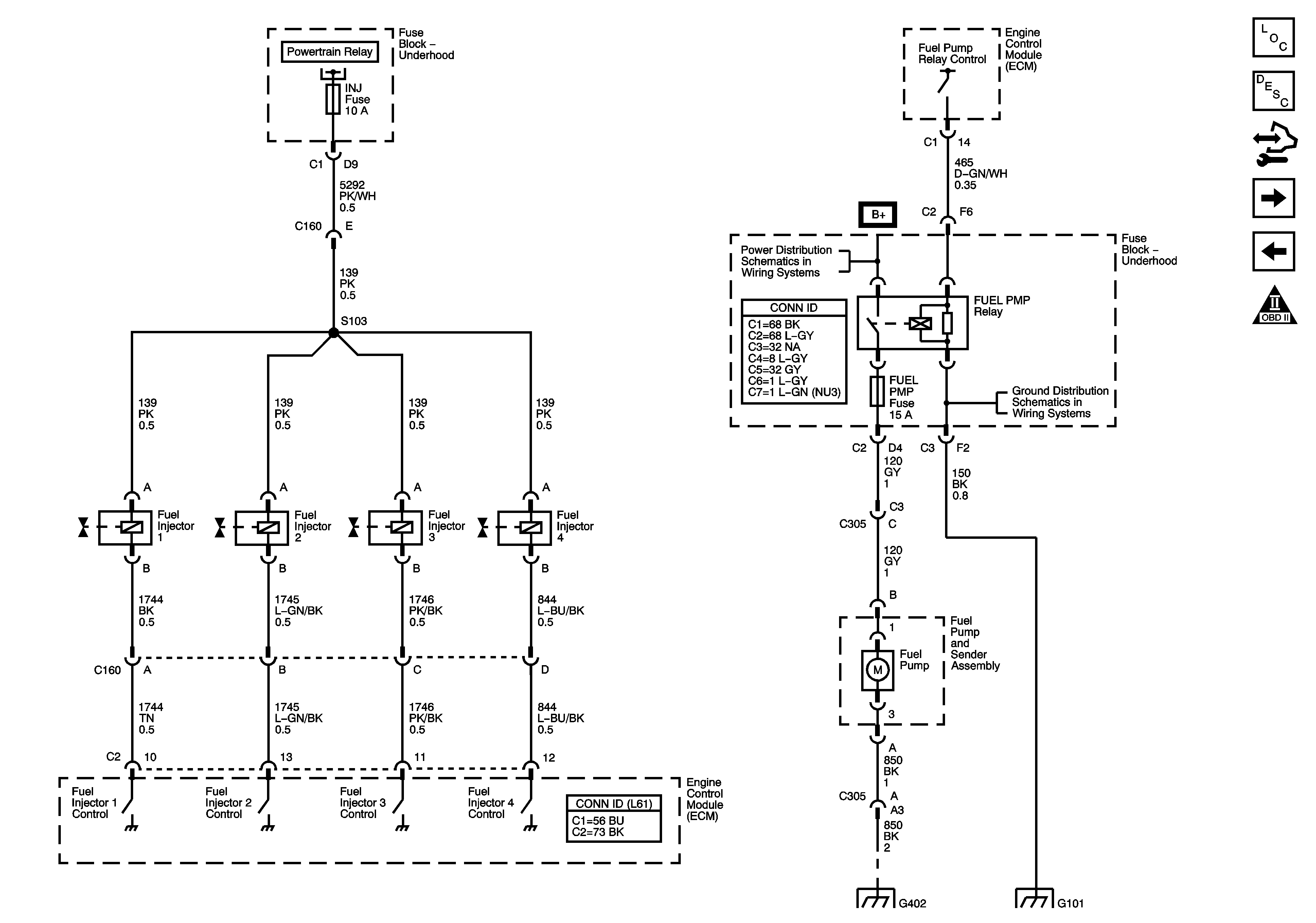
Figure 8:

Fuel Controls and Injectors


Object Number: 1582634  Size: FS
Master Electrical Component List
Fuel System Description
Control Module References
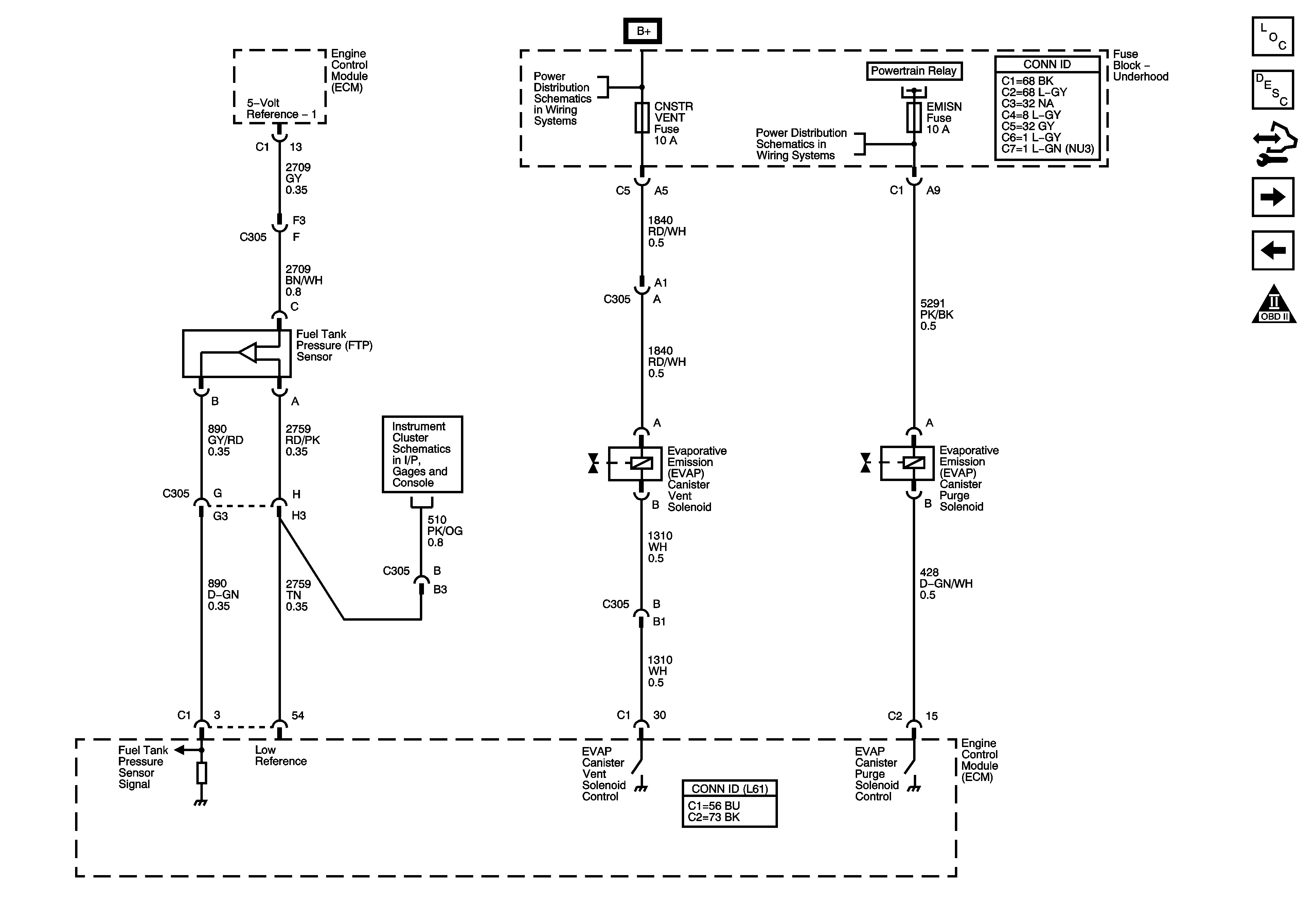
EVAP Controls
Ignition Controls - Ignition System and Sensors
Engine Controls Schematic Icons
G101, G102
G402, G403
G101, G102
Figure 9:

EVAP Controls


Object Number: 1582636  Size: FS
Master Electrical Component List
Evaporative Emission Control System Description
Control Module References
Controlled/Monitored Subsystem References
Fuel Controls and Injectors
Engine Controls Schematic Icons
RUN/CRANK Relay, I/P IGN, BACKUP, ABS, ECM, TRANS, LIGHTING, S-BAND, MIRROR, ABS, EPS, BCM2, BCM3, HEATED SEATS Fuses
FUEL PUMP, POWERTRAIN Relay, FUEL PUMP, EMISSION, INJECTOR Fuses
Ambient Air Temperature Sensor, EOP Sensor, Fuel Level Sensor and Indicator
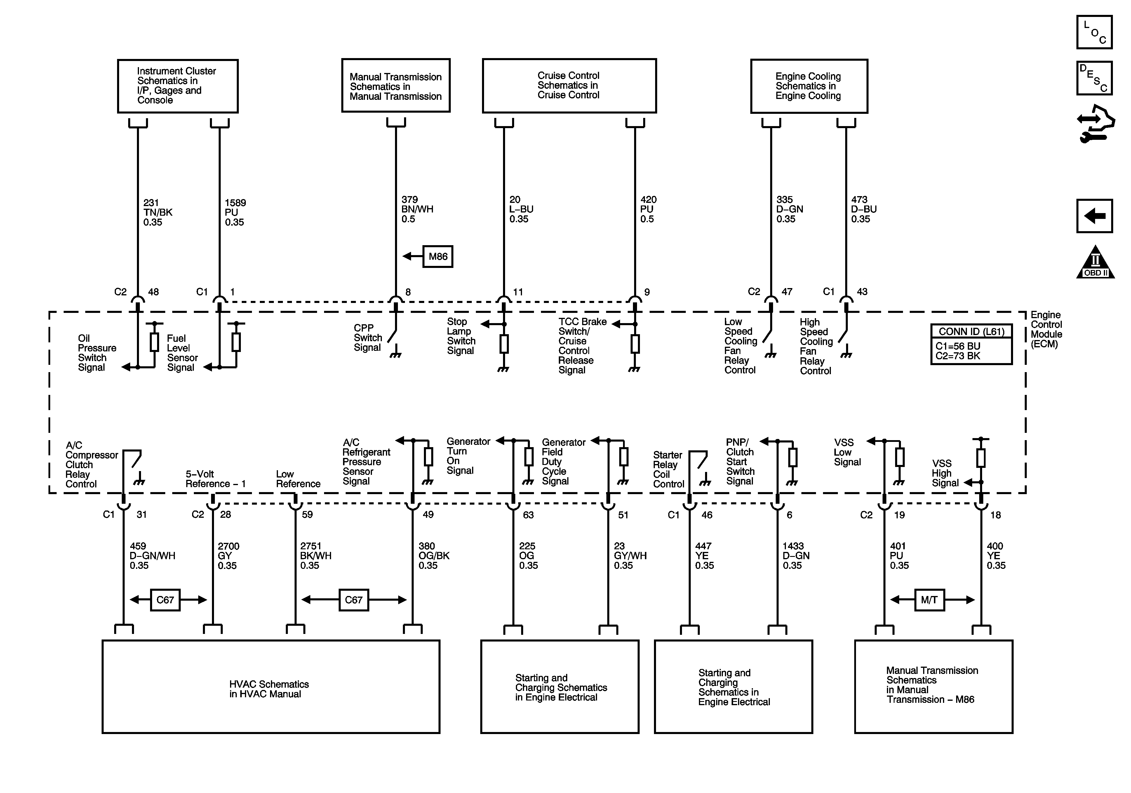
Figure 10:

Controlled/Monitored Subsystem References


Object Number: 1582637  Size: FS
Master Electrical Component List
Engine Control Module Description
Control Module References
EVAP Controls
Engine Controls Schematic Icons
Ambient Air Temperature Sensor, EOP Sensor, Fuel Level Sensor and Indicator
Manual Transmission (L61/2.2L) Schematics
Clutch Pedal Position Switch, Stop Lamp Switch
Cooling Fan and Indicators (L61)
Compressor Controls
Charging
Starting
Manual Transmission (L61/2.2L) Schematics