DTC P0713 3.5L
Circuit Description
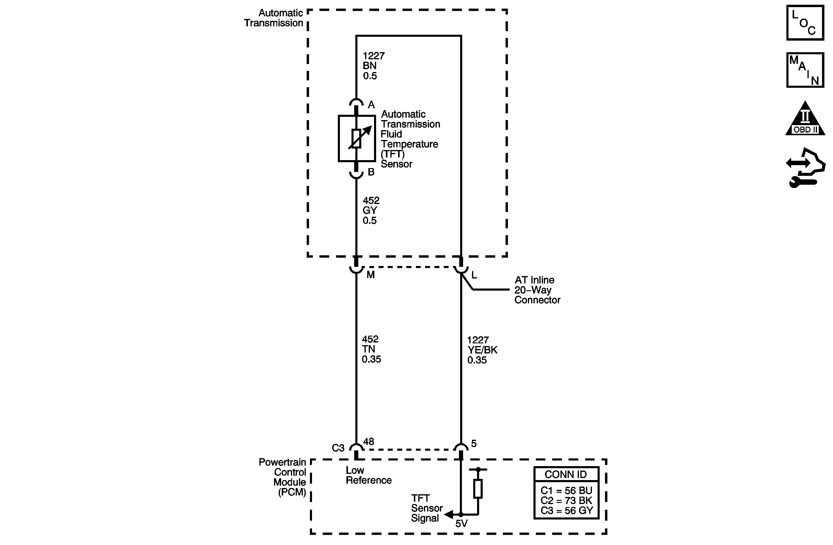
The automatic transmission fluid temperature (TFT) sensor is a negative coefficient thermistor whose resistance value changes based on temperature. The PCM provides a 5-volt reference to the sensor. A low fluid temperature, an open TFT sensor or sensor circuit results in high signal voltage. The TFT operating range is -40 to +151°C (-40 to +304°F).
If the powertrain control module (PCM) detects a continuous open or a short to voltage on the TFT sensor circuit, then DTC P0713 sets. DTC P0713 is a type C DTC.
DTC Descriptor
This diagnostic procedure supports the following DTC:
DTC P0713 Transmission Fluid Temperature (TFT) Sensor Circuit High Voltage
Conditions for Running the DTC
The ignition is ON.
Conditions for Setting the DTC
The PCM detects a TFT sensor voltage 4.92 volts or more for 6 minutes and 40 seconds continuous.
Action Taken When the DTC Sets
| • | The PCM does not turn on the malfunction indicator lamp (MIL). |
| • | The PCM freezes transmission adaptive functions. |
| • | The PCM calculates a default TFT from the ECT sensor and the IAT sensor. |
| • | The PCM records the operating conditions when the Conditions for Setting the DTC are met. The PCM stores this information as Failure Records. |
| • | The PCM stores DTC P0713 in PCM history. |
Conditions for Clearing the DTC
| • | A scan tool can clear the DTC. |
| • | The PCM clears the DTC from PCM history if the vehicle completes 40 warm-up cycles without a non-emission related diagnostic fault occurring. |
| • | The PCM cancels the DTC default actions when the fault no longer exists and the DTC passes. |
Test Description
The numbers below refer to the step numbers on the diagnostic table.
-
A value of 4.9-5.0 volts indicates the PCM and engine side of the wiring are good.
-
A short to voltage greater than 5 volts would cause the TFT sensor to open.
-
A short to the TFT sensor signal circuit and any other circuits in the transmission harness could cause the TFT sensor to open.
Step | Action | Value(s) | Yes | No | ||||
|---|---|---|---|---|---|---|---|---|
1 | Did you perform the Diagnostic System Check - Vehicle? | -- | Go to Step 2 | |||||
2 |
Important: Before clearing the DTCs, use the scan tool in order to record the Failure Records for reference. Using the Clear DTC Information function will erase the stored Failure Records from the PCM. Does the scan tool display a TFT Sensor voltage less than the specified value? | 4.9 V | Go to Testing for Intermittent Conditions and Poor Connections | Go to Step 3 | ||||
Refer to Automatic Transmission Inline 20-Way Connector End View . Does the voltage measure within the specified range? | 4.9-5.0 V | Go to Step 7 | Go to Step 4 | |||||
4 | Does the voltage in Step 3 measure more than the specified value? | 5.0 V | Go to Step 6 | Go to Step 5 | ||||
5 |
Refer to Testing for Continuity and Wiring Repairs . Did you find and correct the condition? | -- | Go to Step 15 | Go to Step 14 | ||||
Test the signal circuit of the TFT sensor for a short to voltage between the PCM and the AT inline 20-way connector. Refer to Testing for a Short to Voltage and Wiring Repairs . Did you find and correct the condition? | -- | Go to Step 12 | Go to Step 14 | |||||
7 |
Refer to Automatic Transmission Inline 20-Way Connector End View . Is the resistance less than the specified value? | 100 K ohms | Go to Step 9 | Go to Step 8 | ||||
8 |
Refer to Testing for Continuity . Did you find the condition? | -- | Go to Step 11 | Go to Step 9 | ||||
Measure the resistance between the TFT sensor signal circuit and all other terminals, except the low reference circuit, of the J 44152 . Is the resistance greater than the specified value? | 1,000 ohms | -- | Go to Step 11 | |||||
10 | Test the signal circuit of the TFT sensor for a short to voltage between the PCM and the AT inline 20-way connector. Refer to Testing for a Short to Voltage and Wiring Repairs . Did you find and correct the condition? | -- | Go to Step 15 | Go to Testing for Intermittent Conditions and Poor Connections | ||||
11 | Replace the automatic transmission wiring harness assembly. Refer to Wiring Harness Replacement . Did you complete the replacement? | -- | Go to Step 12 | -- | ||||
12 | Was the engine harness repaired, or the transmission harness replaced due to a short to power or other circuit? | -- | Go to Step 13 | Go to Step 15 | ||||
13 | Replace the automatic transmission fluid temperature sensor. Refer to Fluid Temperature Sensor Replacement . Did you complete the replacement? | -- | Go to Step 15 | -- | ||||
14 | Replace the PCM. Refer to Control Module References for replacement, setup and programming. Did you complete the replacement? | -- | Go to Step 15 | -- | ||||
15 | Perform the following procedure in order to verify the repair:
Has the test run and passed? | -- | Go to Step 16 | Go to Step 2 | ||||
16 | With the scan tool, observe the stored information, capture info and DTC info. Does the scan tool display any DTCs that you have not diagnosed? | -- | System OK |
DTC P0713 3.9L
Circuit Description
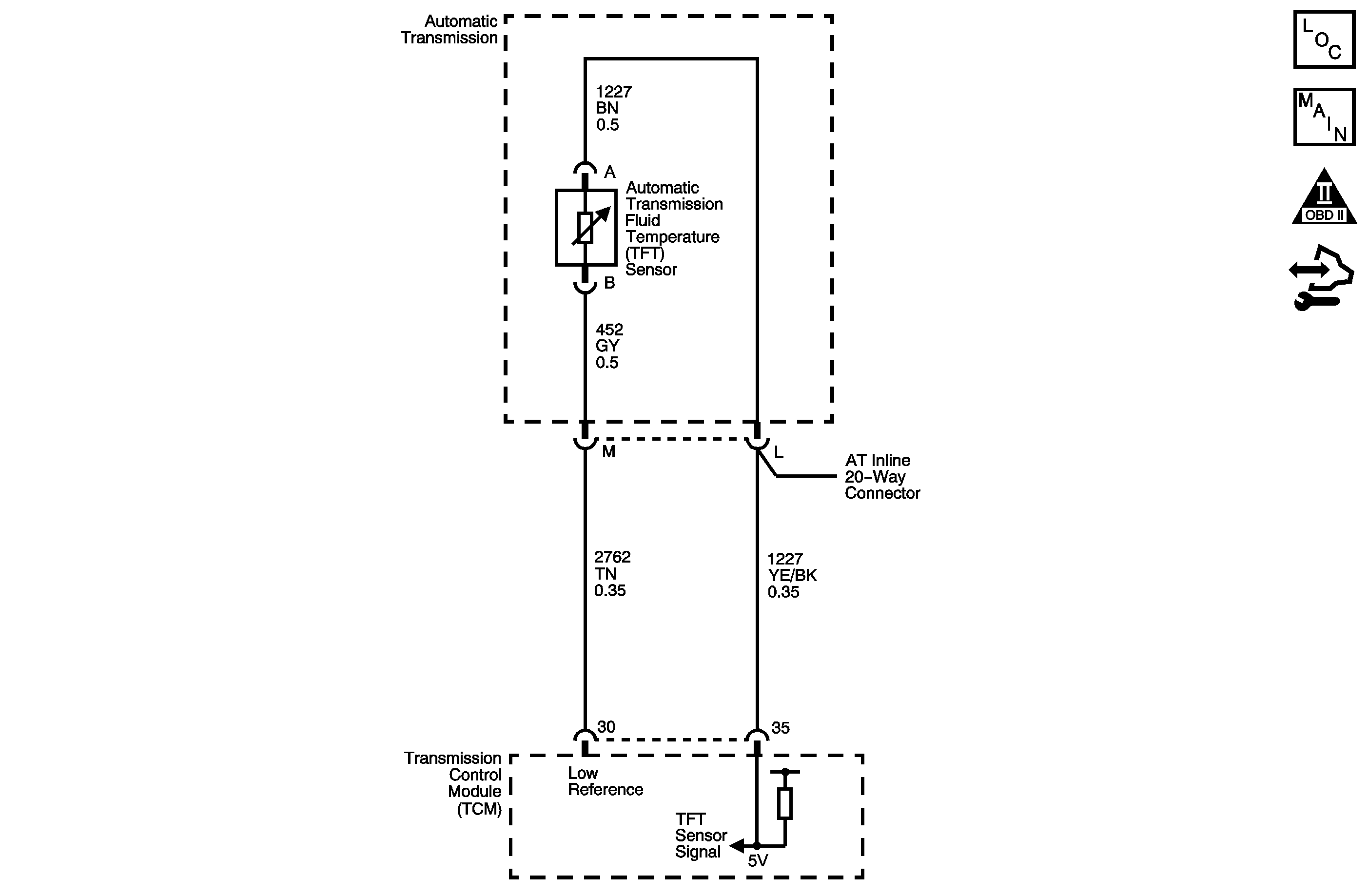
The automatic transmission fluid temperature (TFT) sensor is a negative coefficient thermistor whose resistance value changes based on temperature. The transmission control module (TCM) provides a 5-volt reference to the sensor. A low fluid temperature, an open TFT sensor or sensor circuit results in high signal voltage. The TFT operating range is -40 to +151°C (-40 to +304°F).
If the TCM detects a continuous open or a short to voltage on the TFT sensor circuit, then DTC P0713 sets. DTC P0713 is a type C DTC.
DTC Descriptor
This diagnostic procedure supports the following DTC:
DTC P0713 Transmission Fluid Temperature (TFT) Sensor Circuit High Voltage
Conditions for Running the DTC
| • | No ISS DTC P0716 or P0717. |
| • | No OSS DTC P0722 or P0723. |
| • | The engine is running for 5 seconds. |
| • | The output speed is 70 RPM or greater for 200 seconds cumulatively. |
| • | The TCC slip speed is 120 RPM or greater for 200 seconds cumulatively. |
Conditions for Setting the DTC
The TCM detects a transmission fluid temperature of less than -40°C (-40°F) for 80 seconds.
Action Taken When the DTC Sets
| • | The TCM does not request the ECM to illuminate the malfunction indicator lamp (MIL). |
| • | The TCM freezes transmission adaptive functions. |
| • | The TCM calculates a default TFT from the ECT sensor and the IAT sensor. |
| • | The TCM records the operating conditions when the Conditions for Setting the DTC are met. The TCM stores this information as Failure Records. |
| • | The TCM stores DTC P0713 in TCM history. |
Conditions for Clearing the DTC
| • | A scan tool can clear the DTC. |
| • | The TCM clears the DTC from TCM history if the vehicle completes 40 warm-up cycles without a non-emission related diagnostic fault occurring. |
| • | The TCM cancels the DTC default actions when the fault no longer exists and the DTC passes. |
Test Description
The numbers below refer to the step numbers on the diagnostic table.
-
A value of 4.9-5.0 volts indicates the TCM and engine side of the wiring are good.
-
A short to voltage greater than 5 volts would cause the TFT sensor to open.
-
A short to the TFT sensor signal circuit and any other circuits in the transmission harness could cause the TFT sensor to open.
Step | Action | Value(s) | Yes | No | ||||
|---|---|---|---|---|---|---|---|---|
1 | Did you perform the Diagnostic System Check - Vehicle? | -- | Go to Step 2 | |||||
2 |
Important: Before clearing the DTCs, use the scan tool in order to record the Failure Records for reference. Using the Clear Info function will erase the stored Failure Records from the TCM. Does the scan tool display a TFT Sensor voltage less than the specified value? | 4.9 V | Go to Testing for Intermittent Conditions and Poor Connections | Go to Step 3 | ||||
Refer to Automatic Transmission Inline 20-Way Connector End View . Does the voltage measure within the specified range? | 4.9-5.0 V | Go to Step 7 | Go to Step 4 | |||||
4 | Does the voltage in Step 3 measure more than the specified value? | 5.0 V | Go to Step 6 | Go to Step 5 | ||||
5 |
Refer to Testing for Continuity and Wiring Repairs . Did you find and correct the condition? | -- | Go to Step 14 | Go to Step 13 | ||||
Test the signal circuit of the TFT sensor for a short to voltage between the TCM and the AT inline 20-way connector. Refer to Testing for a Short to Voltage and Wiring Repairs . Did you find and correct the condition? | -- | Go to Step 11 | Go to Step 13 | |||||
7 |
Refer to Automatic Transmission Inline 20-Way Connector End View . Is the resistance less than the specified value? | 100 K ohms | Go to Step 9 | Go to Step 8 | ||||
8 |
Refer to Testing for Continuity . Did you find the condition? | -- | Go to Step 10 | Go to Step 12 | ||||
Measure the resistance between the TFT sensor signal and all other terminals, except the TFT sensor low reference, of the J 44152 . Is the resistance greater than the specified value? | 1,000 ohms | Go to Testing for Intermittent Conditions and Poor Connections | Go to Step 10 | |||||
10 | Replace the automatic transmission wiring harness assembly. Refer to Wiring Harness Replacement . Did you complete the replacement? | -- | Go to Step 11 | -- | ||||
11 | Was the engine harness repaired, or the transmission harness replaced due to a short to power or other circuit? | -- | Go to Step 12 | Go to Step 14 | ||||
12 | Replace the automatic transmission fluid temperature sensor. Refer to Fluid Temperature Sensor Replacement . Did you complete the replacement? | -- | Go to Step 14 | -- | ||||
13 | Replace the TCM. Refer to Control Module References for replacement, setup and programming. Did you complete the replacement? | -- | Go to Step 14 | -- | ||||
14 | Perform the following procedure in order to verify the repair:
Has the test run and passed? | -- | Go to Step 15 | Go to Step 2 | ||||
15 | With the scan tool, observe the stored information, capture info and DTC info. Does the scan tool display any DTCs that you have not diagnosed? | -- | System OK |
