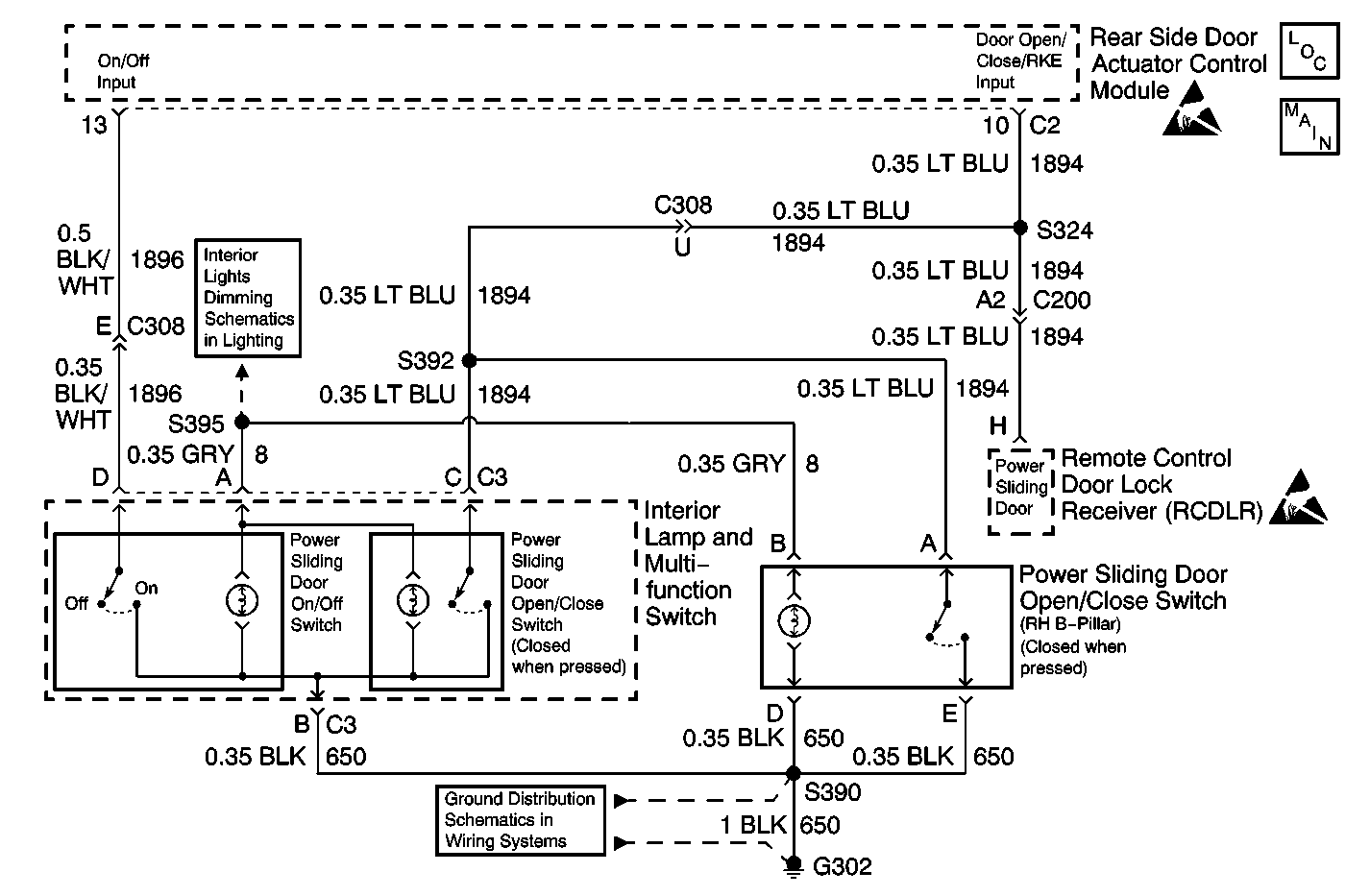
Circuit Description
The Power Sliding Door (PSD) operates through three switches installed on the vehicle and via the keyless entry transmitter.
When the B-pillar PSD open/close switch is pressed, the PSD open/close switch sends a ground signal to the rear side door actuator control module through circuit 1894. This action causes the PSD to either open or close (depending on the position of the door) as long as the power sliding door is unlocked, the transaxle is in PARK (for open command only), and no Diagnostic Trouble Codes (DTCs) are present.
Diagnostic Aids
| • | Inspect for the following conditions: |
| - | A faulty RH B-pillar PSD open/close switch with the internal contacts always open |
| - | An open in circuit 1894 |
| - | An open in circuit 650 |
| • | An intermittent failure may be difficult to detect and to accurately diagnose. Faulty electrical connections or wiring causes most intermittent problems. When an intermittent condition is suspected, inspect the suspected circuits for the following conditions: |
| - | Poor mating of connector halves |
| - | Backed out terminals |
| - | Improperly formed or damaged terminals |
| - | Wire chafing |
| - | Poor wire-to-terminal connections |
| - | Dirty or corroded terminals |
| - | Damaged connector bodies |
| - | A broken wire inside the insulation |
| • | Use a J 35616 whenever a diagnostic procedure requests probing or inspecting a terminal. Using the J 35616 ensures that no damage to the terminal will occur. Using the J 35616 provides an estimate of whether the contact tension is sufficient. |
Test Description
The number(s) below refer to the step number(s) on the diagnostic table.
-
This step performs the Diagnostic Mode 2: Input Test.
-
This step tests for an open in circuit 650.
-
This step tests for a faulty RH B-pillar PSD open/close switch.
-
This step tests for an open in circuit 1894.
Step | Action | Value(s) | Yes | No |
|---|---|---|---|---|
1 | Was the Power Sliding Door (PSD) Diagnostic System Check performed? | -- | Go to Step 2 | |
Does the power sliding door alarm sound as described? | -- | Go to Step 10 | Go to Step 3 | |
Did the test lamp illuminate? | -- | Go to Step 4 | Go to Step 6 | |
Does the resistance measure in the specified range? | Pressed: Less than 2 ohms Released: Infinite | Go to Step 5 | Go to Step 7 | |
Does the resistance measure less than the specified range? | 10 ohms | Go to Step 8 | Go to Step 9 | |
6 | Repair the poor connection or open in circuit 650. Refer to Wiring Repairs or Connector Repairs in Wiring Systems. Is the repair complete? | -- | Go to Step 11 | -- |
7 | Replace the PSD open/close switch (RH B-pillar). Refer to Power Sliding Door (PSD) Open/Close Pillar Switch Replacement . Is the repair complete? | -- | Go to Step 11 | -- |
8 | Check the power sliding door open/close switch (RH B-pillar) harness connector for poor terminal contact. Repair as necessary. Refer to Connector Repairs in Wiring Systems. Is the repair complete? | -- | Go to Step 11 | -- |
9 | Repair the poor connection or open in circuit 1894. Refer to Wiring Repairs or Connector Repairs in Wiring Systems. Is the repair complete? | -- | Go to Step 11 | -- |
10 | Malfunction is not present at this time. Refer to Diagnostic Aids for information on intermittent failures. Is the action complete? | -- | Go to Step 11 | -- |
11 |
Does the PSD operate correctly? | -- | System OK |
