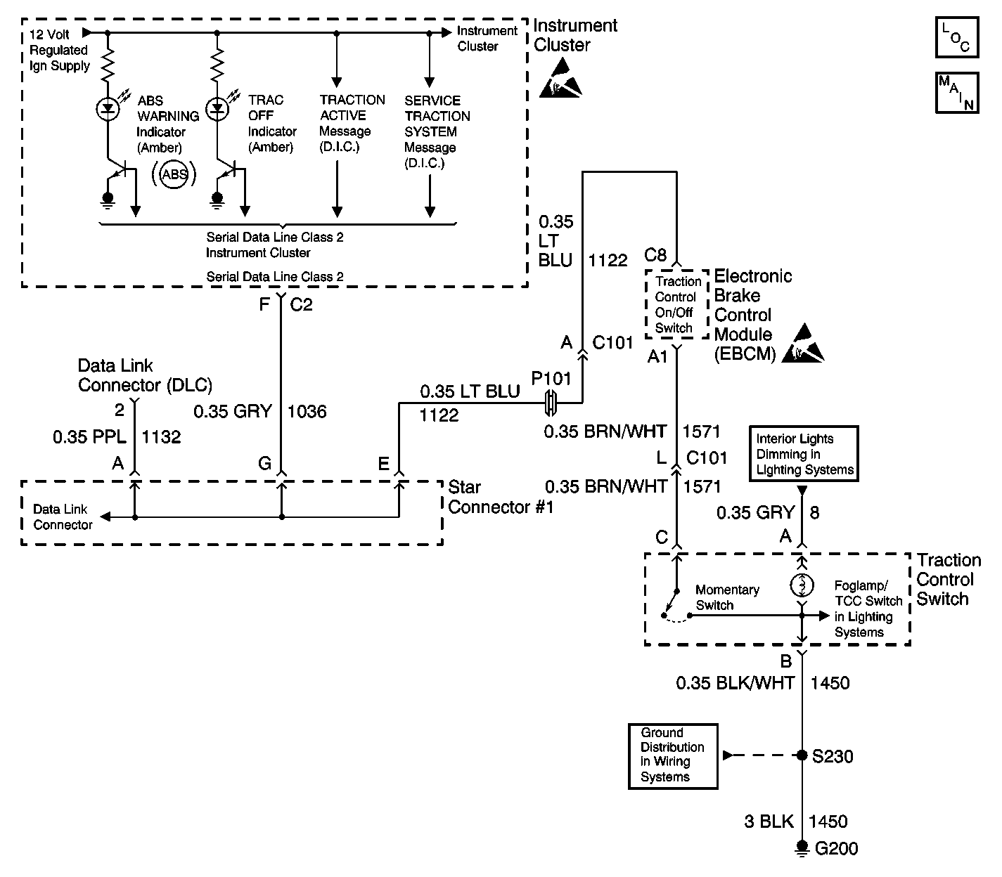
Circuit Description
The Instrument Panel Cluster (IPC) turns the TRAC OFF Indicator on during the IPC bulb check for approximately 3 seconds when the ignition switch is turned to the RUN position. The TRAC OFF indicator is controlled by the EBCM. The TRAC OFF indicator is activated (turned On) when the traction control has been turned off by the driver. When the EBCM detects the traction control switch has been depressed, the TRAC OFF indicator will be turned on/off by sending a Class 2 message to the IPC.
Diagnostic Aids
| • | It is very important that a thorough inspection of the wiring and connectors be performed. Failure to carefully and fully inspect wiring and connectors may result in misdiagnosis, causing part replacement with reappearance of the malfunction. |
| • | Thoroughly inspect any circuitry that may be causing the complaint for the following conditions: |
| - | Backed out terminals |
| - | Improper mating |
| - | Broken locks |
| - | Improperly formed or damaged terminals |
| - | Poor terminal-to-wiring connections |
| - | Physical damage to the wiring harness |
| • | The following conditions may cause an intermittent malfunction: |
| - | A poor connection |
| - | Rubbed-through wire insulation |
| - | A broken wire inside the insulation |
| • | If an intermittent malfunction exists refer to Testing for Intermittent Conditions and Poor Connections in Wiring Systems. |
Step | Action | Value(s) | Yes | No |
|---|---|---|---|---|
DEFINITION: The TRAC OFF indicator remains off at all times even after the Traction Control Switch is pressed to turn the Traction Control on or off. | ||||
1 | Did you perform the ABS Diagnostic System Check? | -- | ||
2 |
Does the TCS Switch state change properly as the switch is pressed and released? | -- | ||
3 | Replace the Instrument Panel Cluster. Refer to Instrument Panel Assembly Replacement Did you complete the repair? | -- | -- | |
4 |
Does the TCS Switch status change with the jumper wire connected? | -- | ||
5 | Replace the Traction Control Switch. Did you complete the repair? | -- | -- | |
6 |
Is the resistance within the range specified in the value(s) column? | 0-2 ohms | ||
7 | Repair the traction control ground circuit for an open or high resistance. Refer to Wiring Repairs Did you complete the repair? | -- | -- | |
8 |
Is the resistance within the range specified in the value(s) column? | 0-2 ohms | ||
9 | Repair the traction control ground circuit for an open or high resistance. Refer to Wiring Repairs Did you complete the repair? | -- | -- | |
10 | Replace the EBCM. Refer to Electronic Brake Control Module Replacement Did you complete the repair? | -- | -- | |
11 |
Does the DTC reset? | -- | System OK | |
