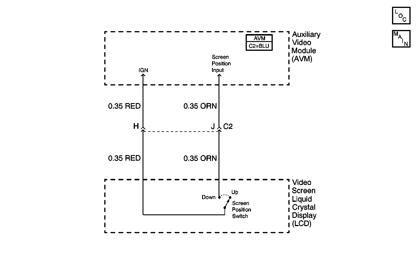
Circuit Description
The Auxiliary Video Module (AVM) controls the operation of the Video Entertainment System (VES). The AVM turns on the VES when the video screen is placed in the down position. The AVM determines when the video screen is in the down position by means of a screen position switch located in the video screen.
The video screen is of a Liquid Crystal Display (LCD) type, and it uses backlighting when the video screen power is on. The video screen turns on when the ignition switch is on and the video screen is in the down position.
The video screen produces images based on the video signal coming from the VCP or the auxiliary source of video.
Diagnostic Aids
| • | Check for the following conditions: |
| - | RED and ORN wires are either shorted together, or shorted to B+ between the AVM and the video screen. |
| - | A faulty video screen. |
| • | An intermittent failure may be very difficult to detect and to diagnose accurately. Faulty electrical connections or wiring causes most intermittent problems. When an intermittent condition is suspected, check the suspected circuits for the following conditions: |
| - | Improperly formed or damaged terminals. |
| - | Wire chafing. |
| - | Damage to connector bodies. |
Test Description
The number(s) below refer to the step number(s) on the diagnostic table.
-
Checks for the ORN and RED wires shorted together (screen position switch circuits).
-
Verifies repairs made to the VES.
Step | Action | Value(s) | Yes | No |
|---|---|---|---|---|
DEFINITION: The video display does not turn off when the video screen is in the up (stored) position. The Video Entertainment System (VES) also remains on. Note: The VES (including the video screen) turn off when the ignition switch is off. | ||||
Check the RED and ORN wires (screen position circuits) between the Auxiliary Video Module (AVM) and the video screen; make sure they are not shorted together or shorted to voltage. Are circuits in good condition? | -- | Go to Step 2 | Go to Step 3 | |
2 | Replace the video screen. Refer to Video Display Replacement . Is the repair complete? | -- | Go to Step 4 | -- |
3 | Repair the RED and ORN wires(screen position circuits) between the AVM and the video screen. Is the repair complete? | -- | Go to Step 4 | -- |
Does the VES operate normally? | -- | System OK | ||
