For 1990-2009 cars only
Removal Procedure
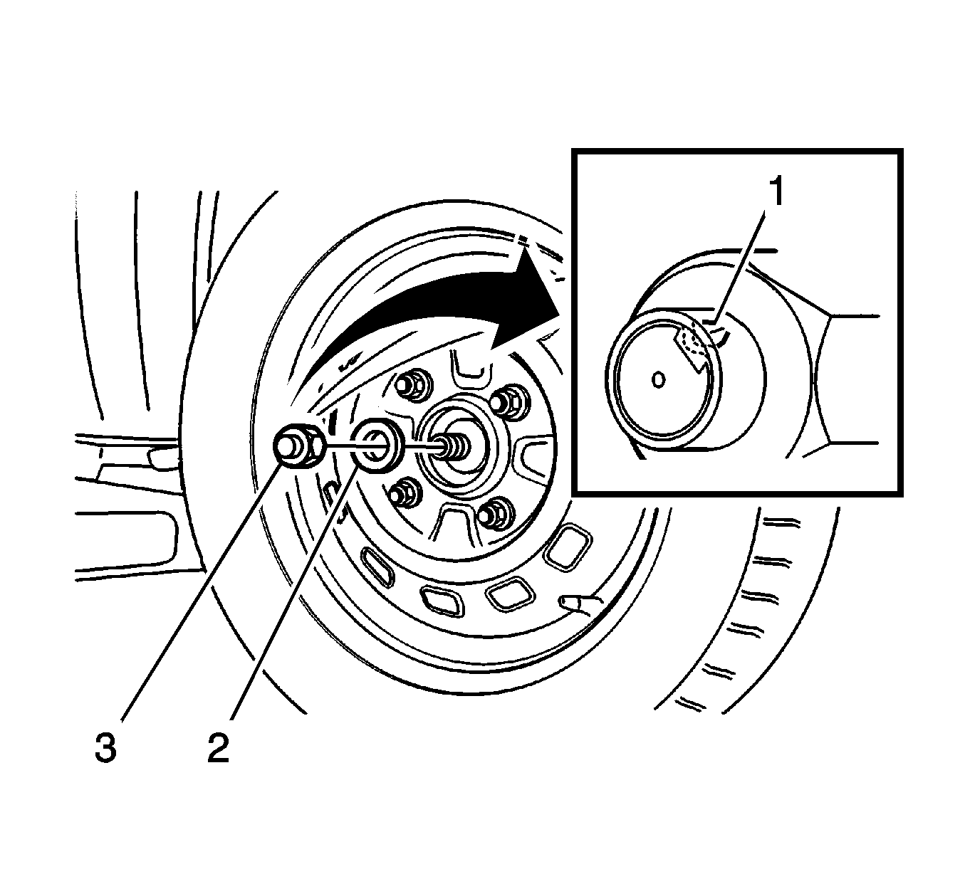
- Press the brake pedal in order to disable the rotation of the hub.
- Loosen the caulking (1).
- Remove the drive axle shaft nut (3).
- Discard the nut.
- Remove the washer (2).
- Remove the wheel and tire assembly
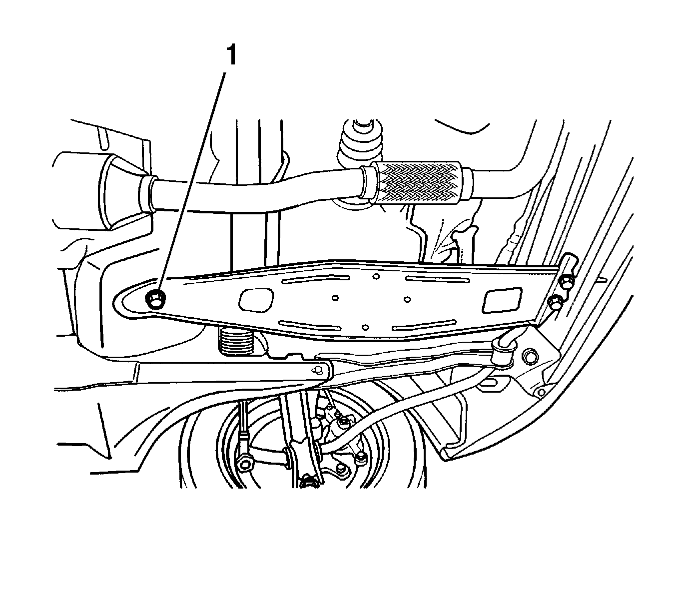
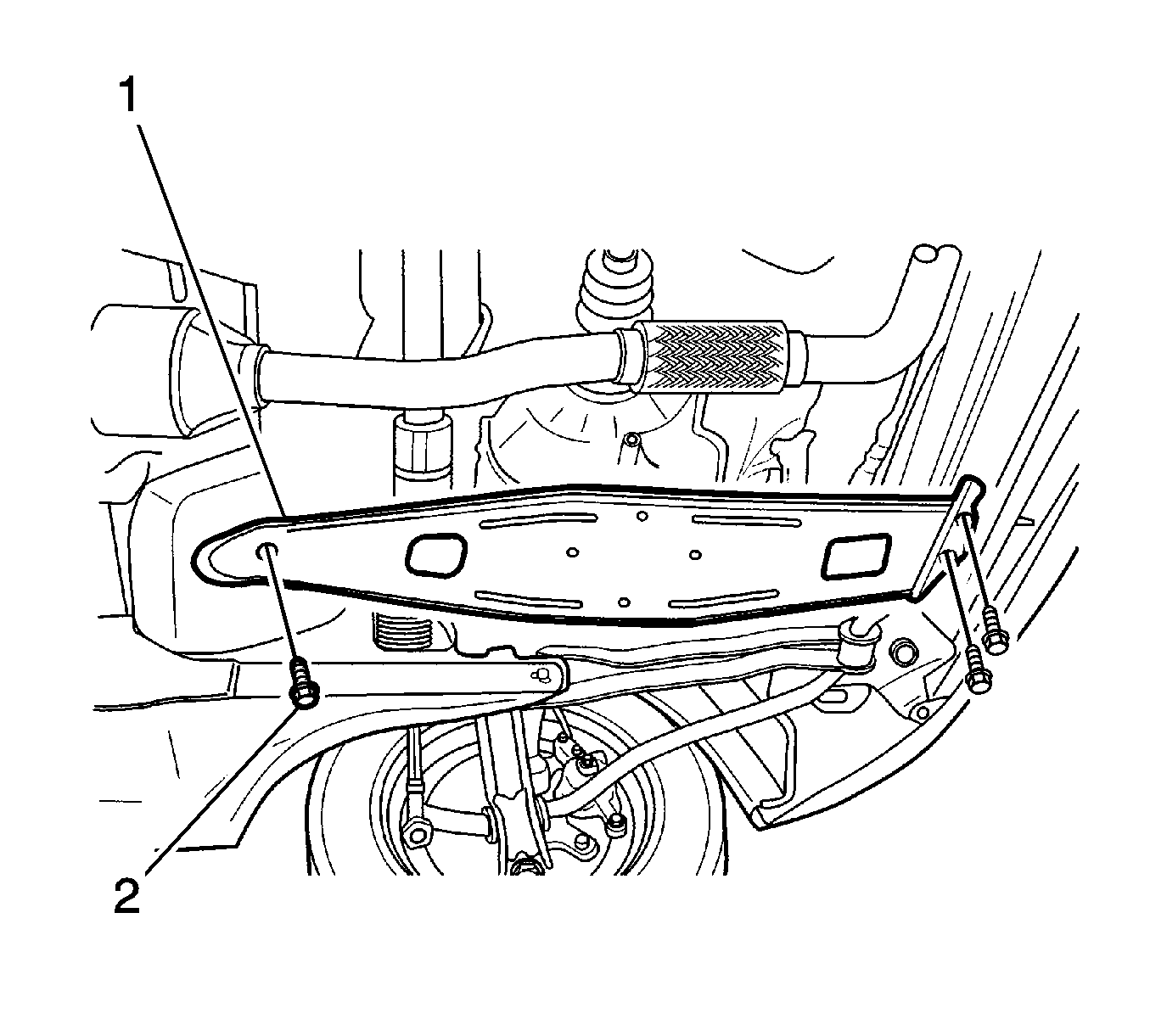
- Remove the transaxle under cover bolts (2).
- Remove the transaxle under cover (1).
- Drain the transaxle fluid through the drain plug.
- Remove the strut bar. Refer to Stabilizer Shaft Replacement.
- Separate the control arm ball joint (1) and the tie rod end from the knuckle (2). Refer to Steering Knuckle Replacement
- Pull the drive axle shaft (1) from the wheel hub.
- Insert a flat-head screwdriver between the transaxle case and the drive axle joint case (2).
- Remove the drive axle (1) from the transaxle.
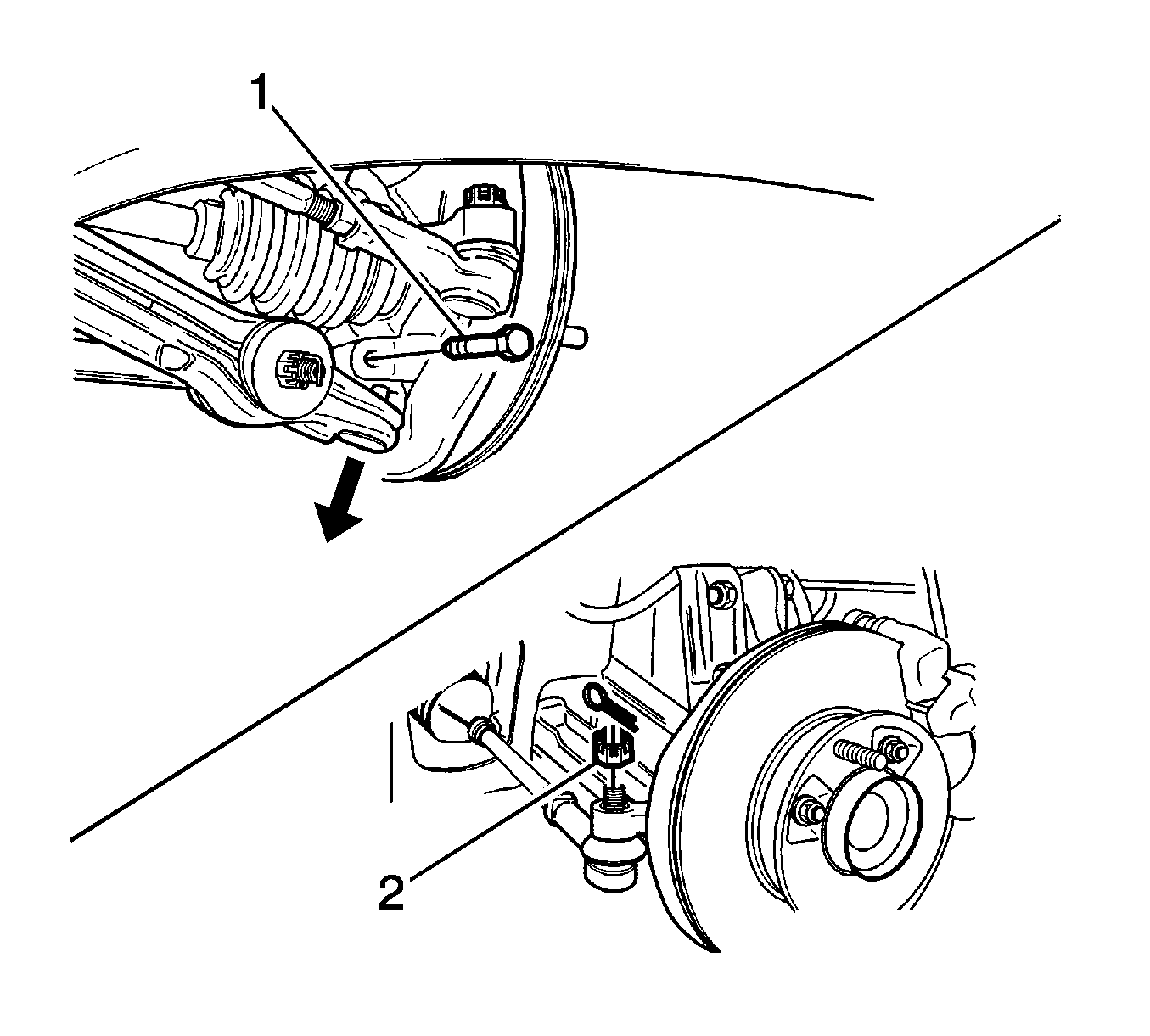
Caution: Use only the recommended tool for separating the tie rod from the knuckle/strut assembly. Failure to use the recommended tool may cause damage to the knuckle/strut assembly of the tie rod end.
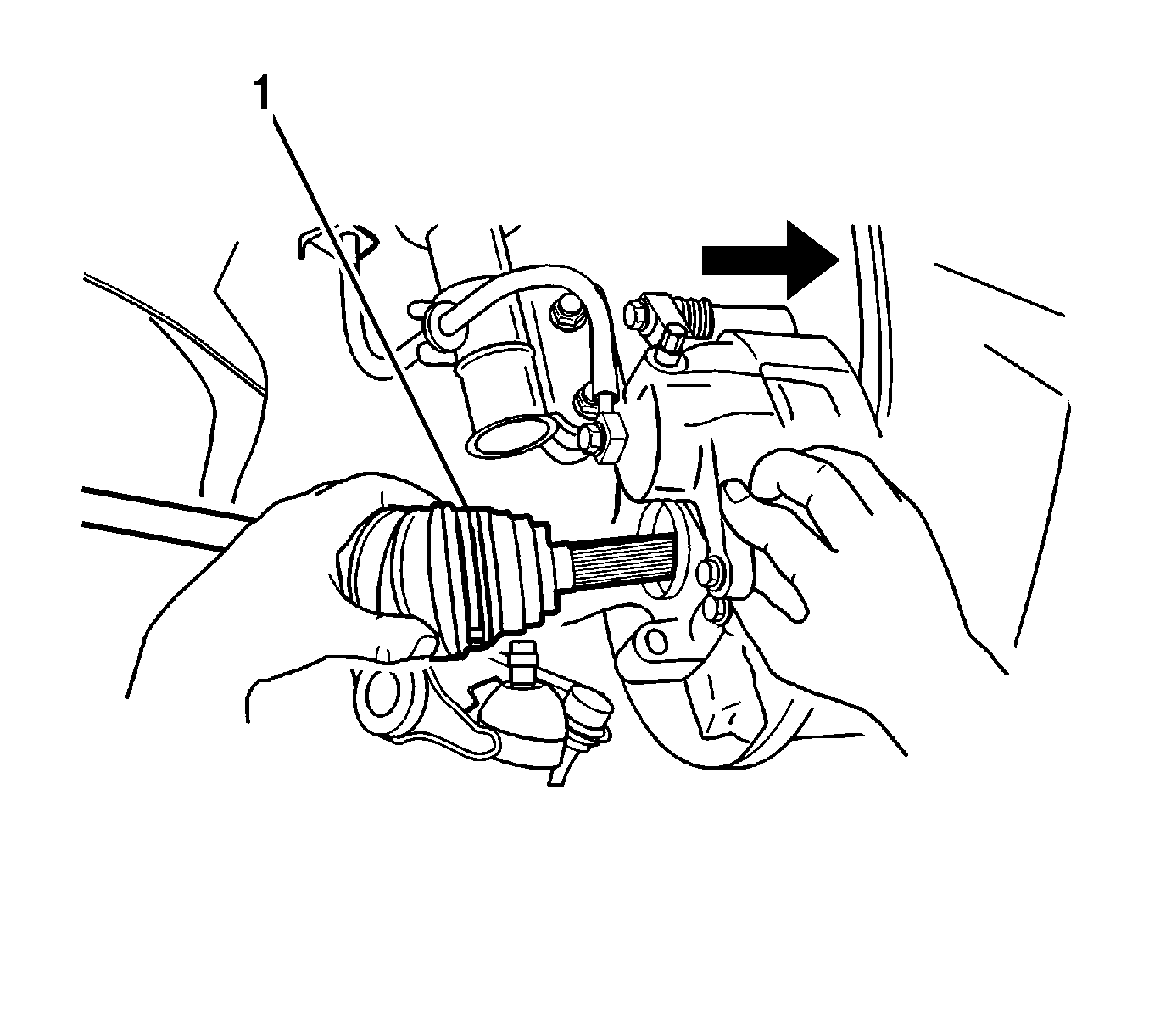
Note: Support the unfastened end of the drive axle. Do not allow the drive axle to dangle freely from the transaxle for any length of time after it has been removed from the wheel hub.
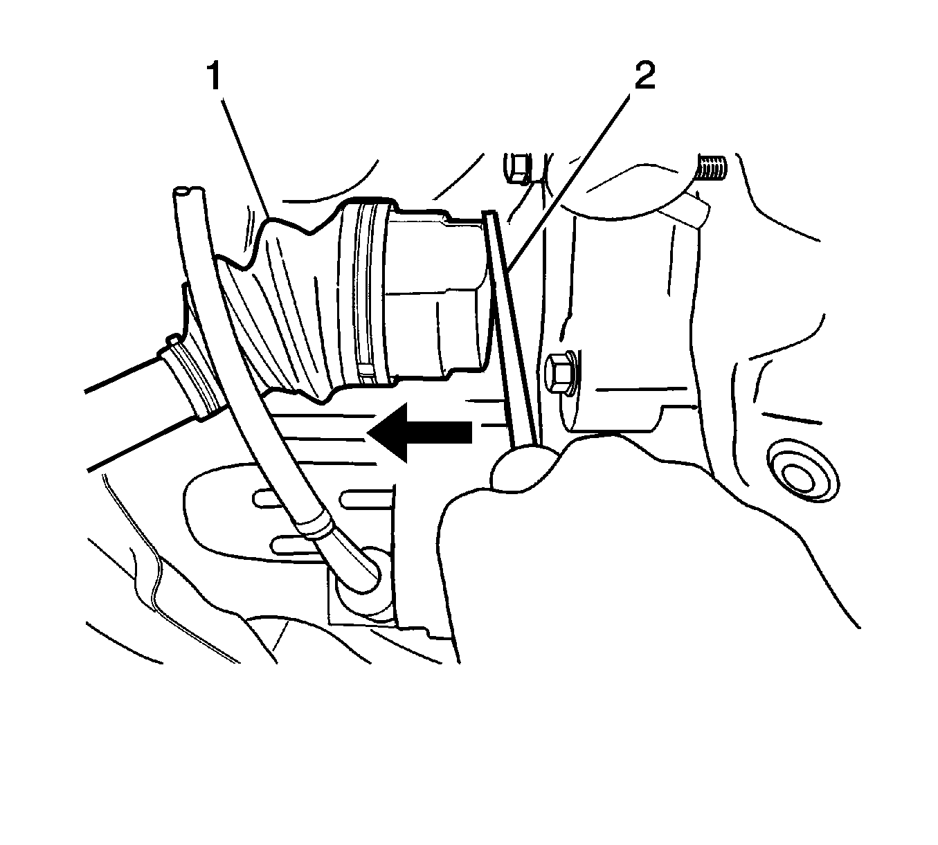
Caution: Refer to Drive Axle Caution in the Preface section.
Inspection Procedure
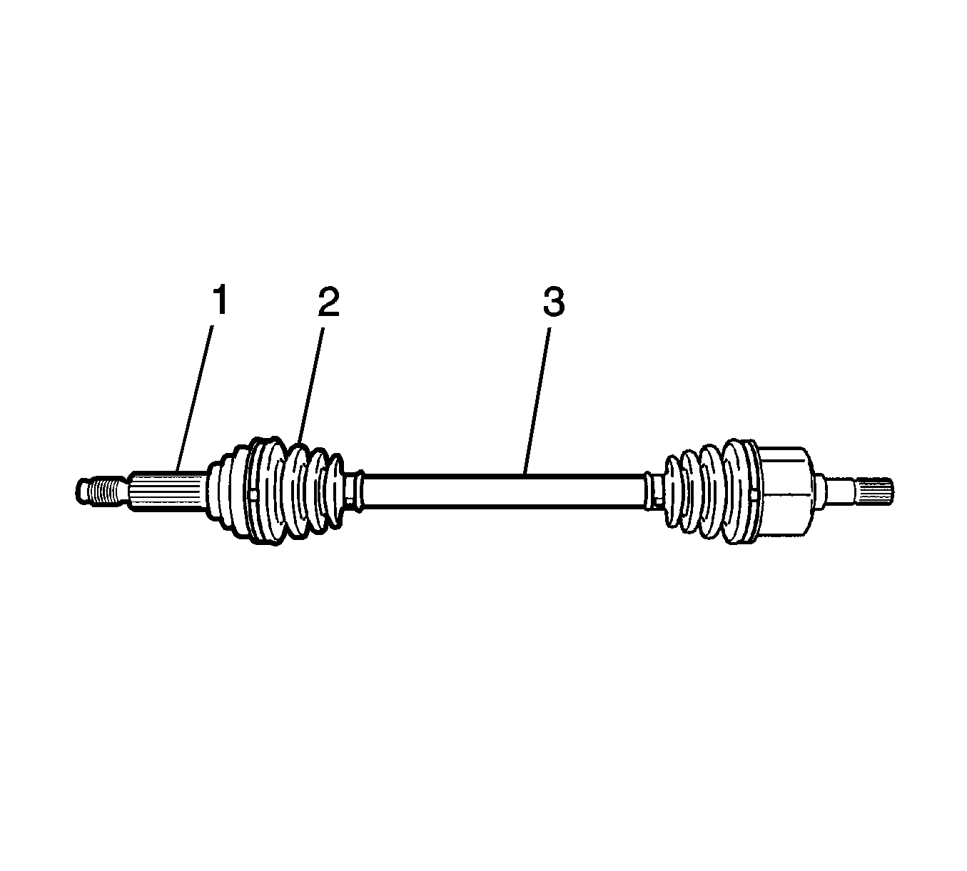
- Inspect for worn or damaged spline of drive axle (1).
- Inspect for a leaking boot (2).
- Inspect for a bent shaft (3).
Installation Procedure
- Clean the transaxle seal.
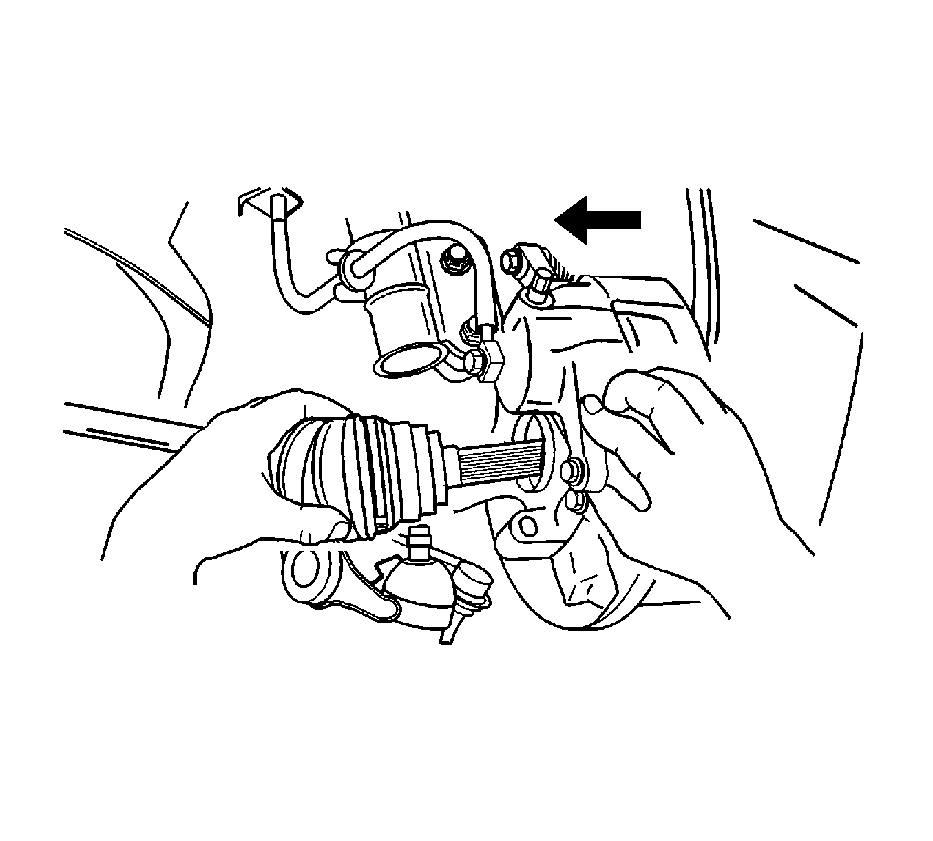
- Install the drive axle into the transaxle.
- Install the wheel hub onto the drive axle shaft.
- Mount the knuckle onto the control arm ball joint. Refer to Steering Knuckle Replacement
- Install the control arm ball joint bolt (1) and tighten to 50-70 N·m (36-52 lb ft).
- Install the tie rod into the knuckle and install the tie rod end joint castellated nut (2). Tighten the tie rod end joint castellated nut to 30-55 N·m (21-41 lb ft).
- Install the strut bar, strut bar mounting bolts (1) and castellated nut (2).
- Install the drive axle shaft nut (2) and tighten to 210 N·m (155 lb ft).
- Install the wheel and tire assembly.
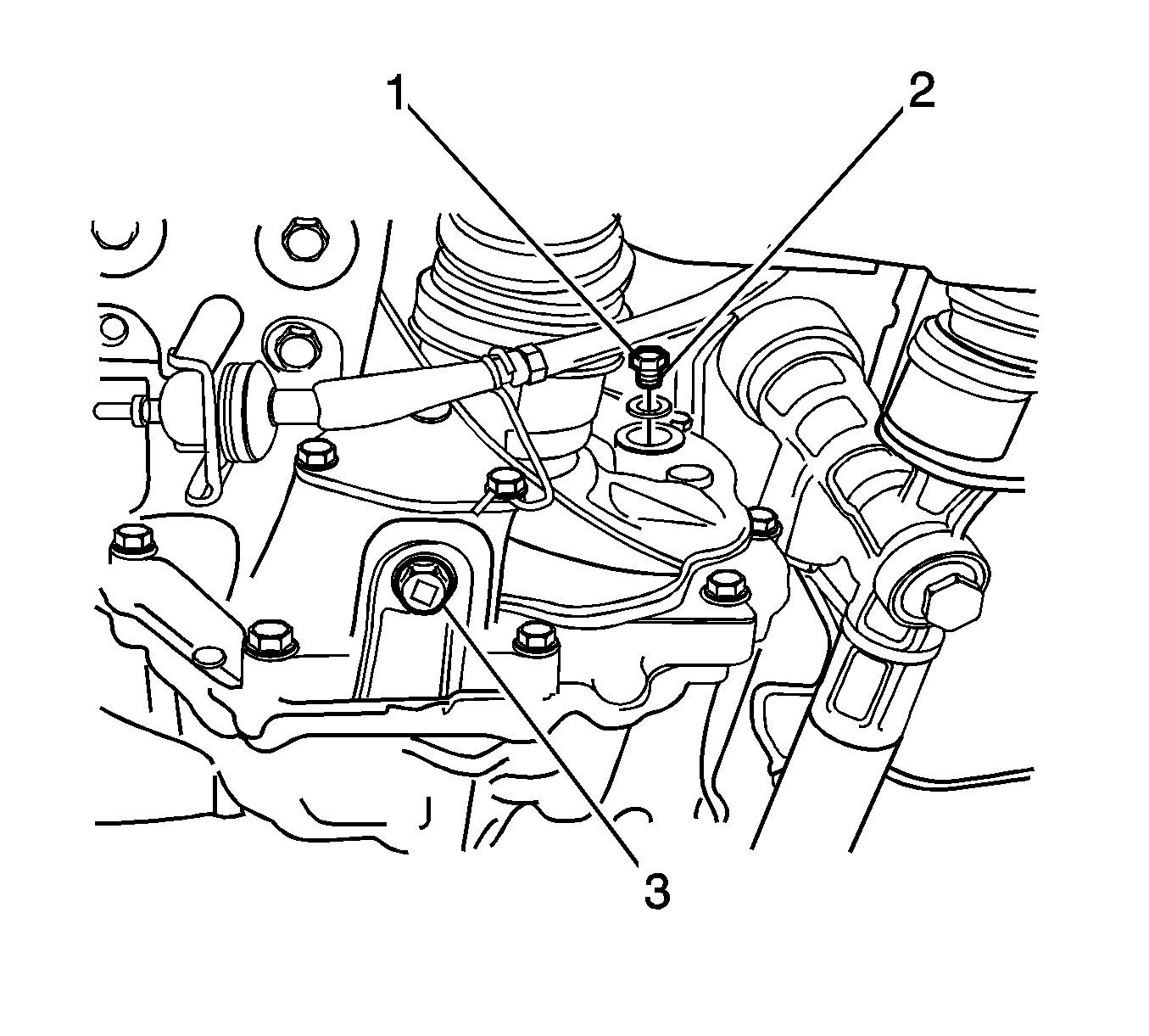
- Install the drain plug (3) and tighten to 25-30 N·m (18-22 lb ft).
- Remove the oil level plug (1).
- Refill recommended fluid to the proper level.
- Install the oil level plug (2) and tighten to 36-54 N·m (26-40 lb ft).
- Install the transaxle under cover with the bolts (1) and tighten to 35-55 N·m (25-41 lb ft).
Caution: Refer to Fastener Caution in the Preface section.
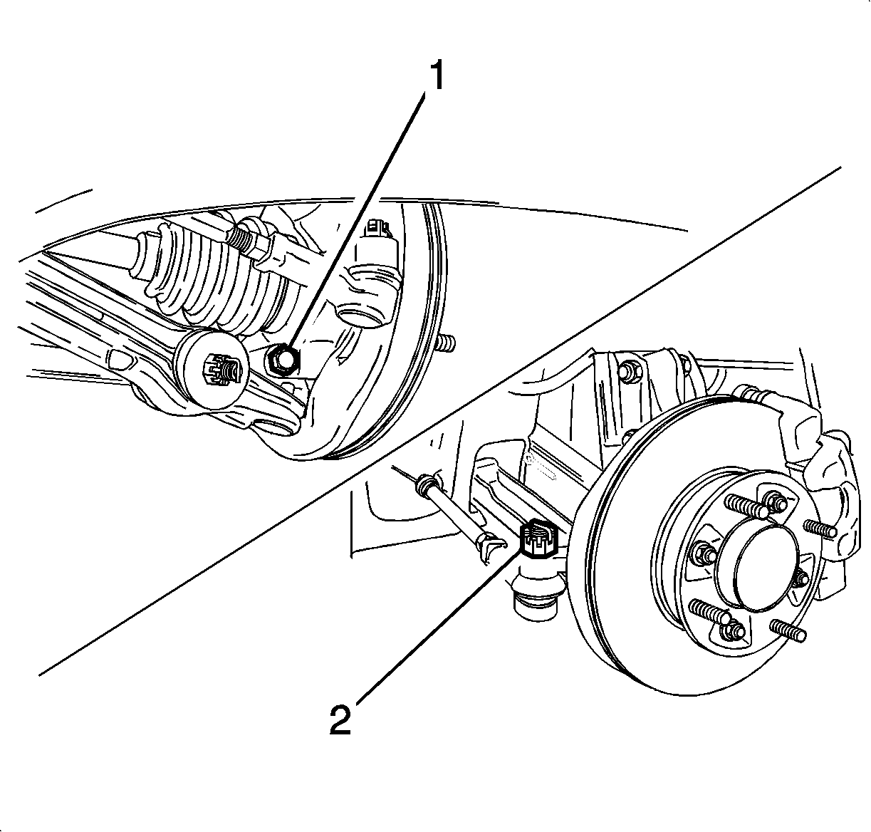
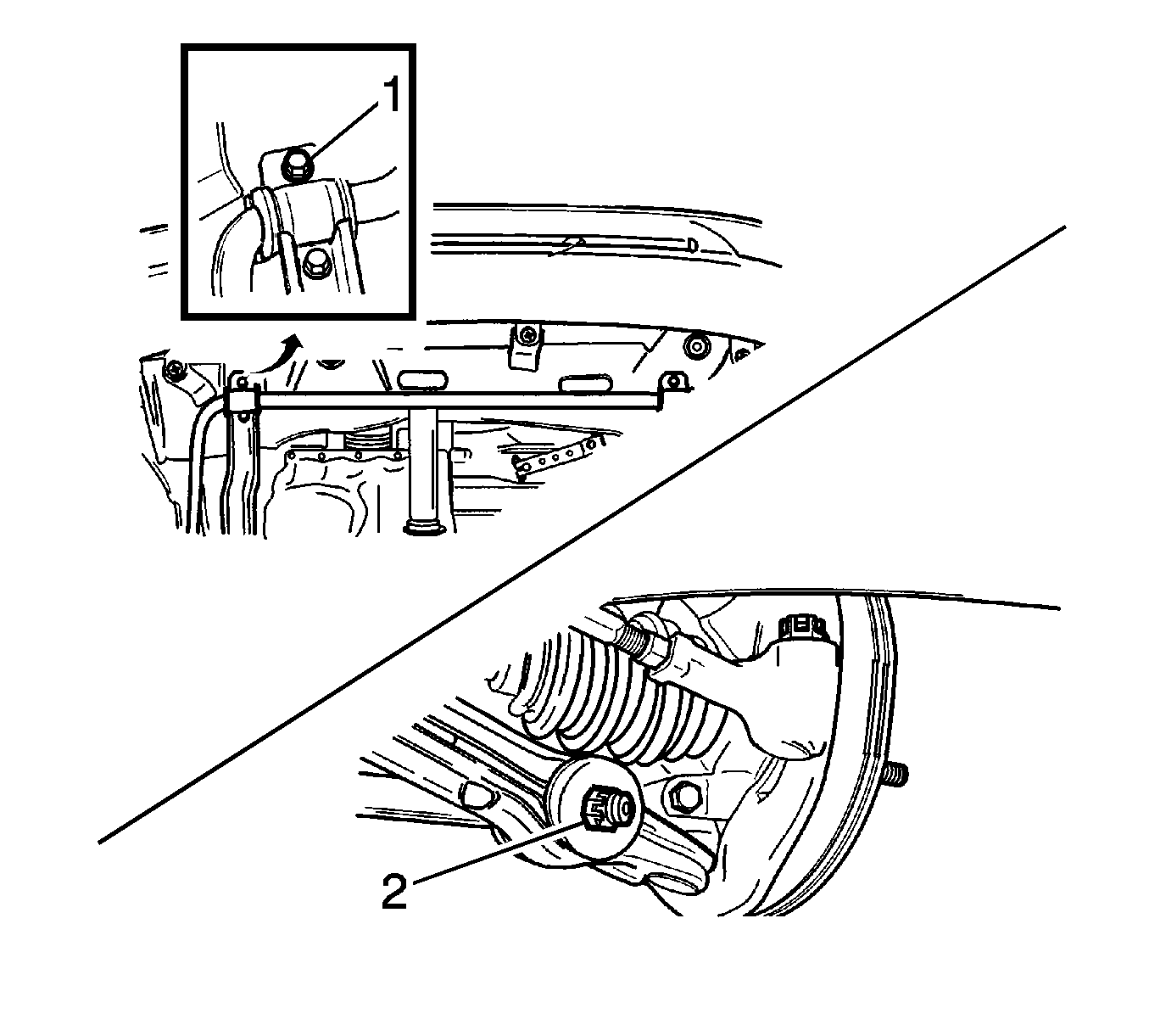
| • | Tighten the strut bar mounting bolts to 33-53 N·m (24-39 lb ft). |
| • | Tighten the strut bar castellated nut to 40-50 N·m (30-36 lb ft). |
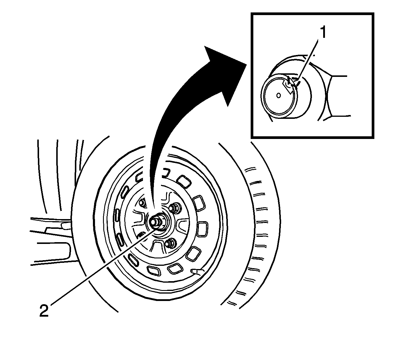
Note: Always use a new nut. Always peen the caulking nut with a punch and a hammer until the nut is locked into place on the wheel hub.
Classification
75W-85 (GL-4)
Capacity
2.1L (2.21 qt)
