For 1990-2009 cars only
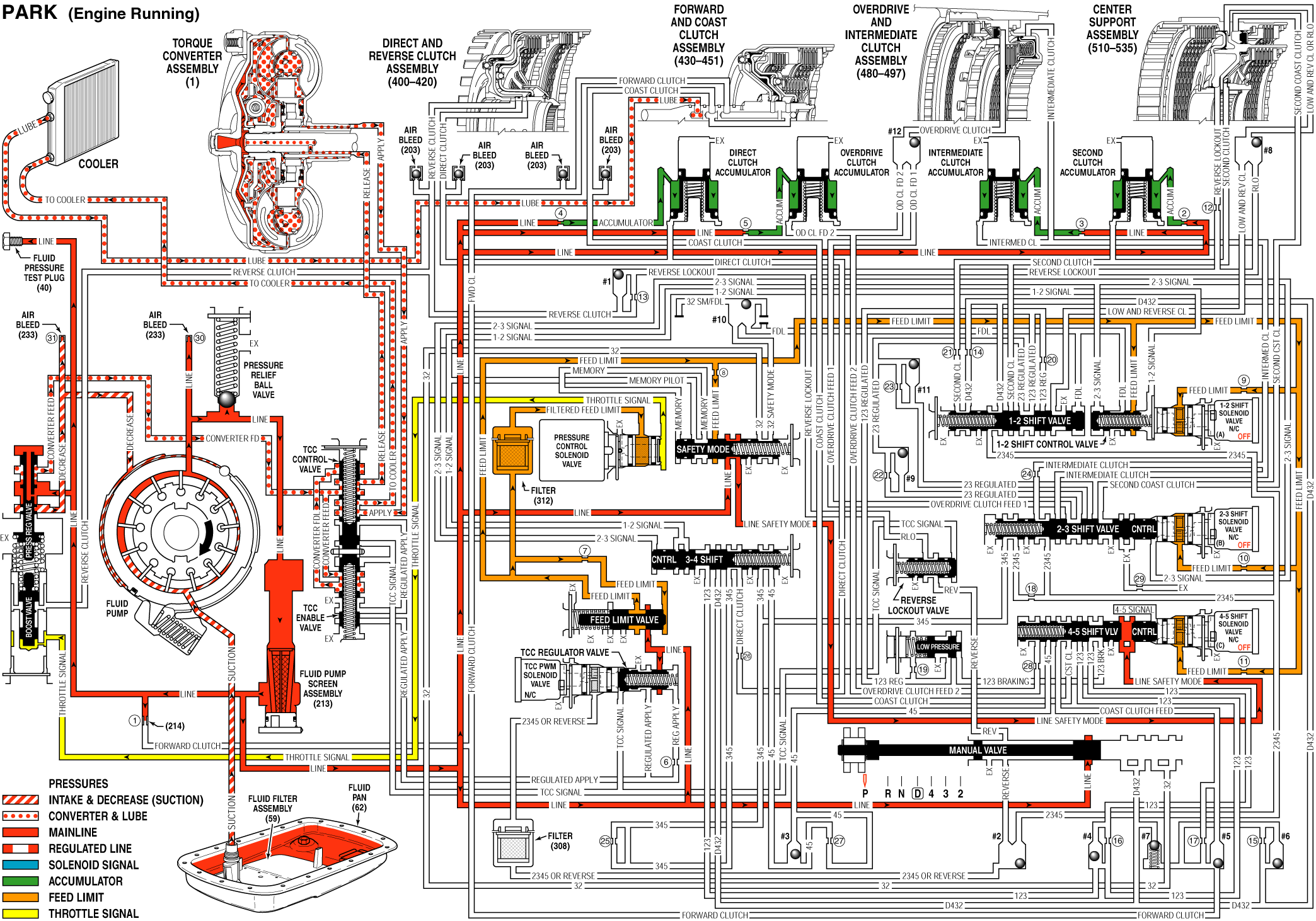
When the gear selector lever is in the Park (P) position and the engine is running, fluid is drawn into the oil pump and line pressure is directed to the pressure regulator valve.
Pressure Regulation
Pressure Regulator Valve: Regulates pump output - line pressure in response to throttle signal fluid pressure acting on the line boost valve, spring force, and line pressure acting on the end of the valve. Line pressure is directed to the manual valve, the TCC regulator valve, feed limit valve, and the safety mode valve. Line pressure also feeds the converter feed circuit through the pressure regulator valve, and the accumulator fluid circuits.Feed Limit Valve: Line pressure is routed through the valve and into the feed limit fluid circuit. The valve limits feed limit fluid pressure to a maximum pressure. Feed limit fluid is routed to the pressure control solenoid valve, the safety mode valve, the 1-2 control valve, and also feeds the 1-2 signal, the 2-3 signal, and the 4-5 signal fluid circuits.
Pressure Control (PC) Solenoid Valve: Controlled by the TCM, the PC solenoid valve regulates filtered feed limit fluid pressure into the throttle signal fluid circuit.
Shift Accumulation
Direct, Overdrive, Intermediate, and Second Clutch Accumulator Assemblies: Accumulator fluid is routed to each of the accumulator assemblies in preparation for upshifts and downshifts.Torque Converter - Released Position Only
Pressure Regulator Valve: Line pressure is routed through the pressure regulator valve and into the converter feed fluid circuit. Converter feed fluid is routed to the TCC control valve and to the TCC enable valve.TCC Regulator Valve: Spring force holds the valve in the release position, thereby blocking line pressure from entering the regulated apply fluid circuit.
TCC Enable Valve: Converter feed fluid is routed through the TCC enable valve and into the converter FDL circuit. Converter FDL fluid is routed to the TCC control valve.
TCC Control Valve: Spring force holds the valve in the release position allowing converter feed fluid to enter the release circuit.
Torque Converter: Release fluid pressure is routed to the torque converter to keep the TCC released. Fluid leaves the converter in the apply fluid circuit and returns to the cooler through the TCC control valve.
Safety Mode:
Safety Mode Valve: When the first 1-2 shift occurs, the safety mode valve shifts from the released position to the applied position and remains there until the engine is switched OFF. If safety mode occures - no TCM signal to the shift solenoid valve, the transmission will shift to safety - fifth gear. If the engine is then switched OFF and ON, still with no TCM signal, the safety mode valve will return to, and remain in, the released position. Line pressure fluid will pass through the safety mode valve into the line safety mode fluid circuit. Line safety mode fluid is routed to the 4-5 shift valve train.4-5 Shift Valve and 4-5 Shift Control Valve: Line safety mode fluid forces the 4-5 shift valve to downshift to the fourth gear position allowing - after the engine has been switched OFF, a fourth gear start - instead of fifth, in the event of safety mode.
Fluid Pressure Directied in Preparation for a Shift
Manual Valve: Mechanically controlled by the gear selector lever, the manual valve is in the Park (P) position and prevents line pressure from the pressure regulator valve from entering the reverse, D432 and 32 fluid circuits.1-2 Shift Solenoid (SS) Valve and 1-2 Shift Control Valve: Feed limit fluid from the feed limit valve is routed to the 1-2 SS valve and to the 1-2 Shift control valve in preparation for a shift.
2-3 Shift Solenoid (SS) Valve: Feed limit fluid from the feed limit valve is routed to the 2-3 SS valve in preparation for a shift.
4-5 Shift Solenoid (SS) Valve: Feed limit fluid from the feed limit valve is routed to the 4-5 SS valve in preparation for a shift.
Direct Clutch, Overdrive Clutch, Intermediate Clutch, and Second Clutch Accumulators: Line fluid fills the accumulator circuits and accumulator assemblies in preparation for an upshift.
Park Engine Running

