GM Service Manual Online
For 1990-2009 cars only
Figure 1:

PCM Power, Ground, MIL, and Serial Data
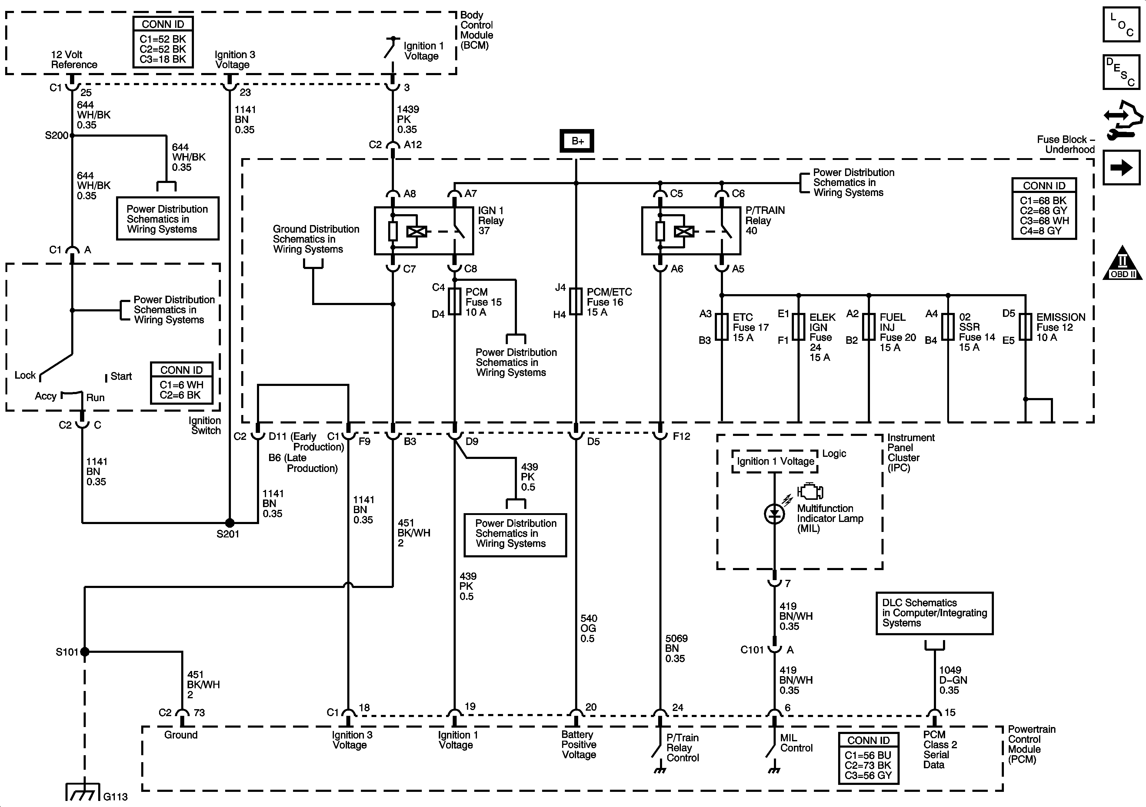

Object Number: 1653933  Size: FS
Master Electrical Component List
Powertrain Control Module Description
Control Module References
5-Volt Low Reference Bussing
Engine Controls Schematic Icons
Ignition Switch
Ignition Switch
G101, G112 (L26/L32), and G113 (L26/L32)
Fuse Block Underhood Bussing
ABS, TRANS SOL, PCM, SIR, DISPLAY, CRUISE SW Fuses, and CRANK Relay
L26/L32
G101, G112 (L26/L32), and G113 (L26/L32)
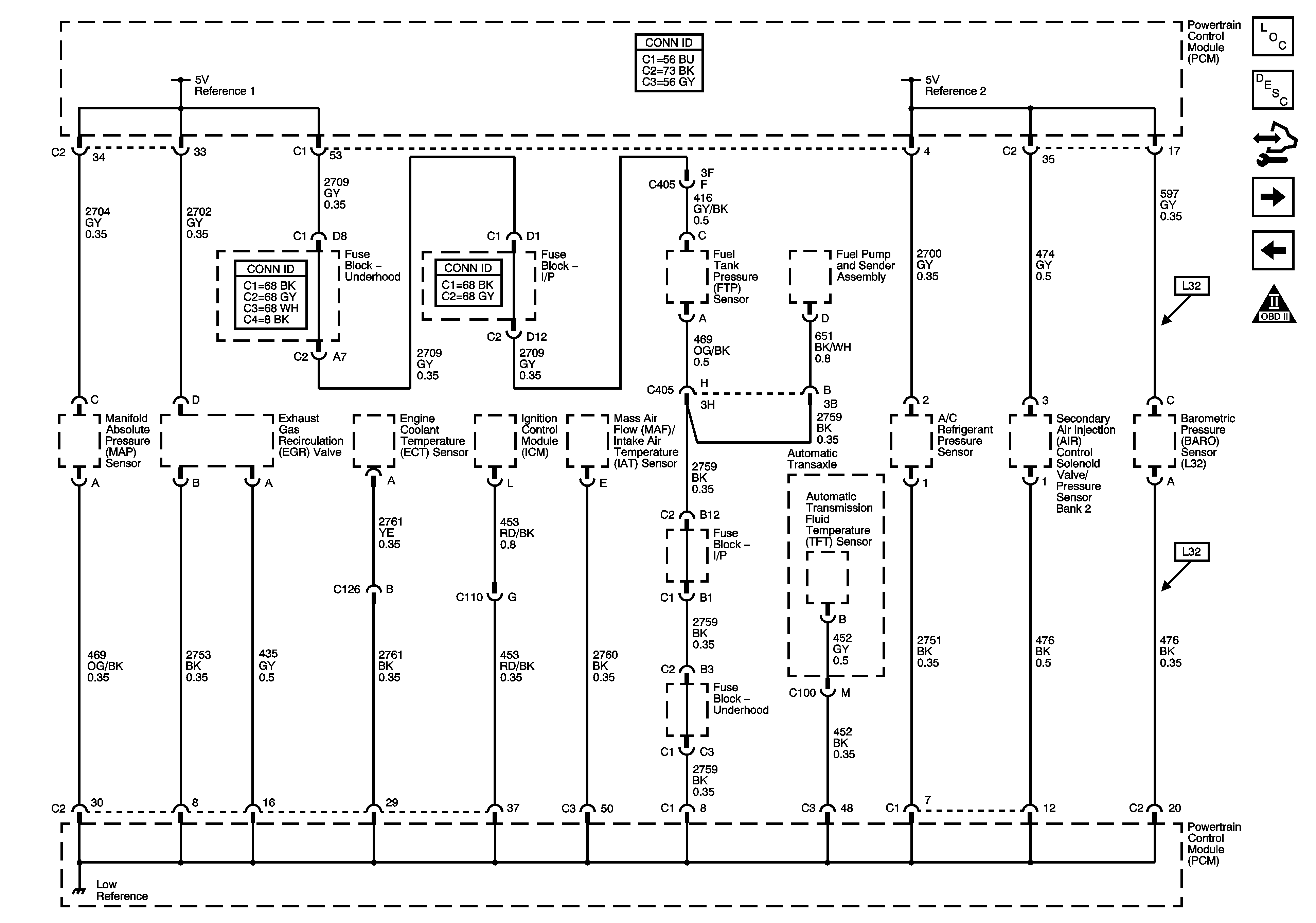
Figure 2:

5-Volt and Low Reference Bussing


Object Number: 1653934  Size: FS
Master Electrical Component List
Powertrain Control Module Description
Control Module References
BARO, MAP, ECT, and IAT/MAF Sensors
PCM Power, Ground, MIL, and Serial Data
Engine Controls Schematic Icons
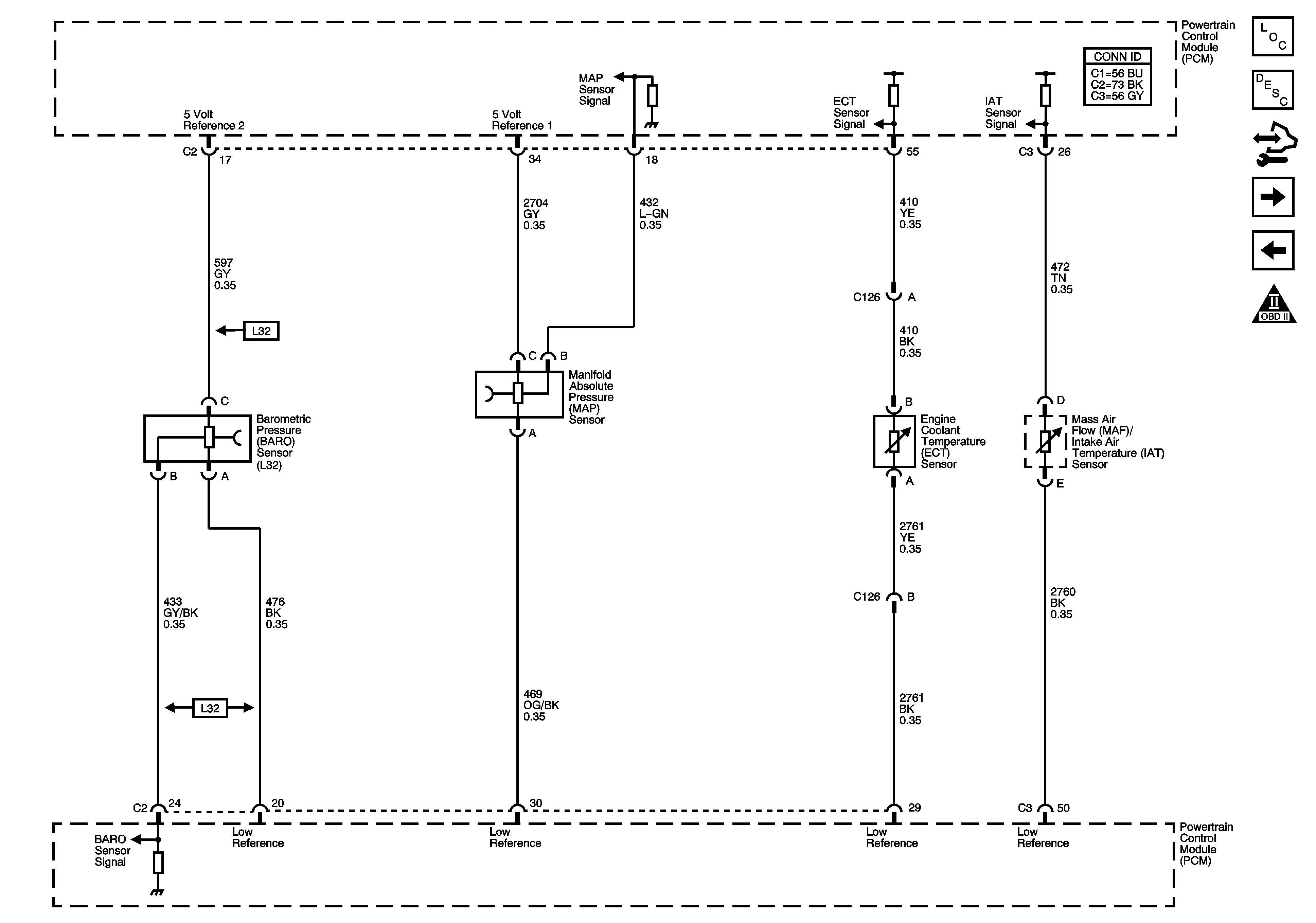
Figure 3:

BARO, MAP, ECT, and IAT/MAF Sensors


Object Number: 1653935  Size: FS
Master Electrical Component List
Powertrain Control Module Description
Control Module References
IAT/MAF Sensor, Super Charger Boost Control Solenoid and A/T Controls VSS References
5-Volt Low Reference Bussing
Engine Controls Schematic Icons
Figure 4:

IAT/MAF Sensor, Super Charger Boost Control Solenoid, and A/T Controls VSS References
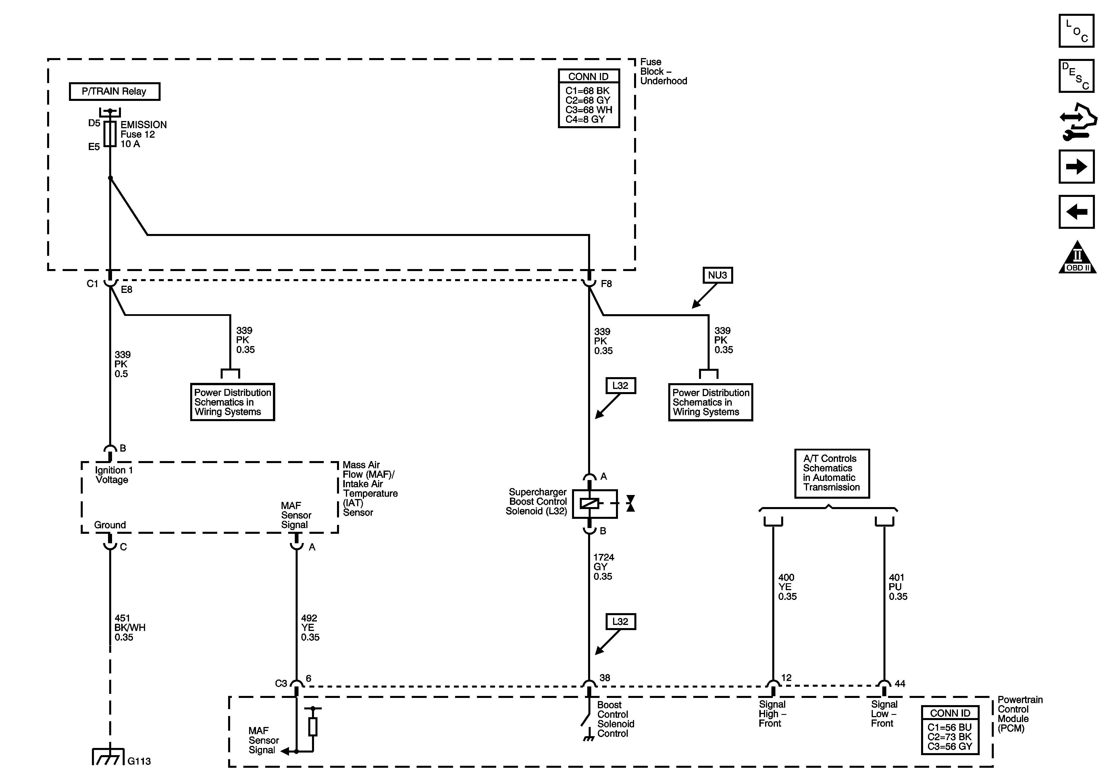

Object Number: 1653936  Size: FS
Master Electrical Component List
Boost Control System Description
Control Module References
Heated Oxygen Sensors
BARO, MAP, ECT, and IAT/MAF Sensors
Engine Controls Schematic Icons
Fuse Block Underhood Bussing
ETC, ELEC IGN, FUEL INJ, O2 SSR, and EMISSION Fuses
VSS and AT Sensors, Pressure Control Solenoid Valve and TCC Release Switch
G101, G112 (L26/L32), and G113 (L26/L32)
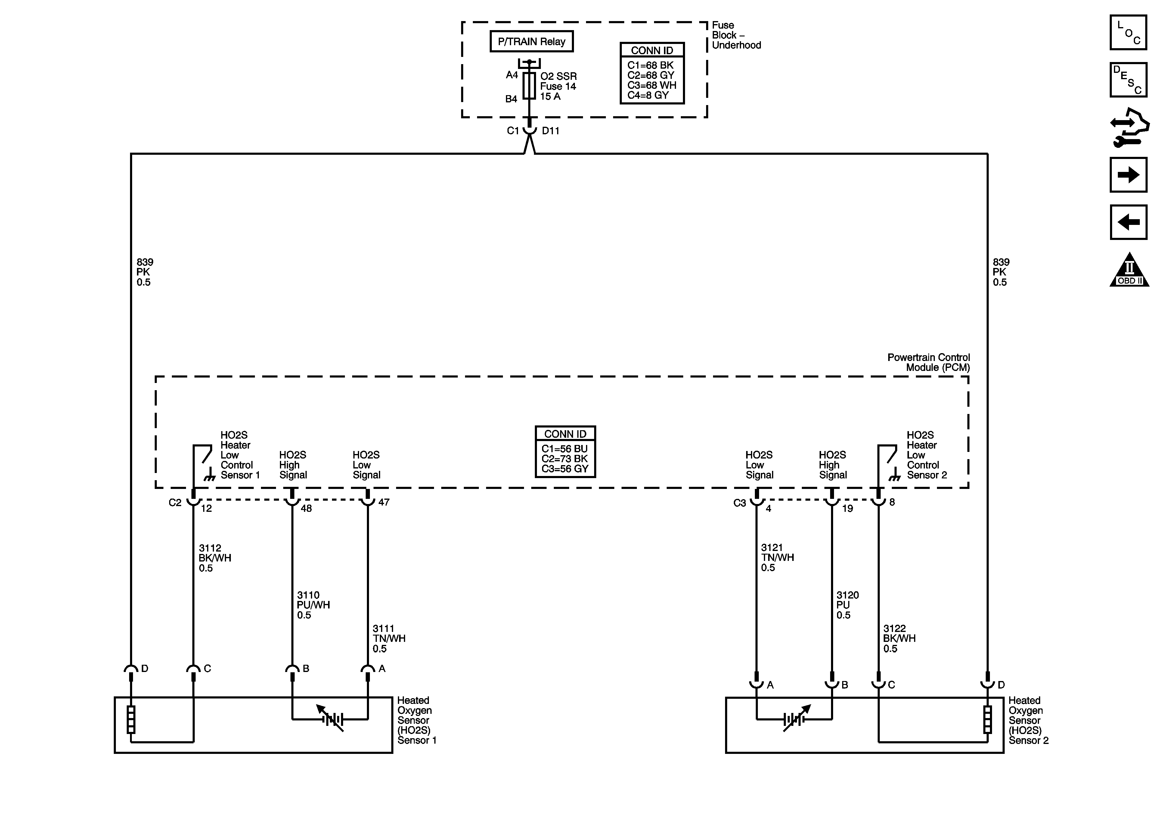
Figure 5:

Heated Oxygen Sensors


Object Number: 1653938  Size: FS
Master Electrical Component List
Powertrain Control Module Description
Control Module References
Electronic Throttle Controls
IAT/MAF Sensor, Super Charger Boost Control Solenoid and A/T Controls VSS References
Engine Controls Schematic Icons
Fuse Block Underhood Bussing
Figure 6:

Electronic Throttle Controls


Object Number: 1653939  Size: FS
Master Electrical Component List
Throttle Actuator Control (TAC) System Description
Control Module References
Ignition Control Module
Heated Oxygen Sensors
Engine Controls Schematic Icons
Fuse Block Underhood Bussing
Indicator, ABS, Stability, and Traction Controls
G101, G112 (L26/L32), and G113 (L26/L32)
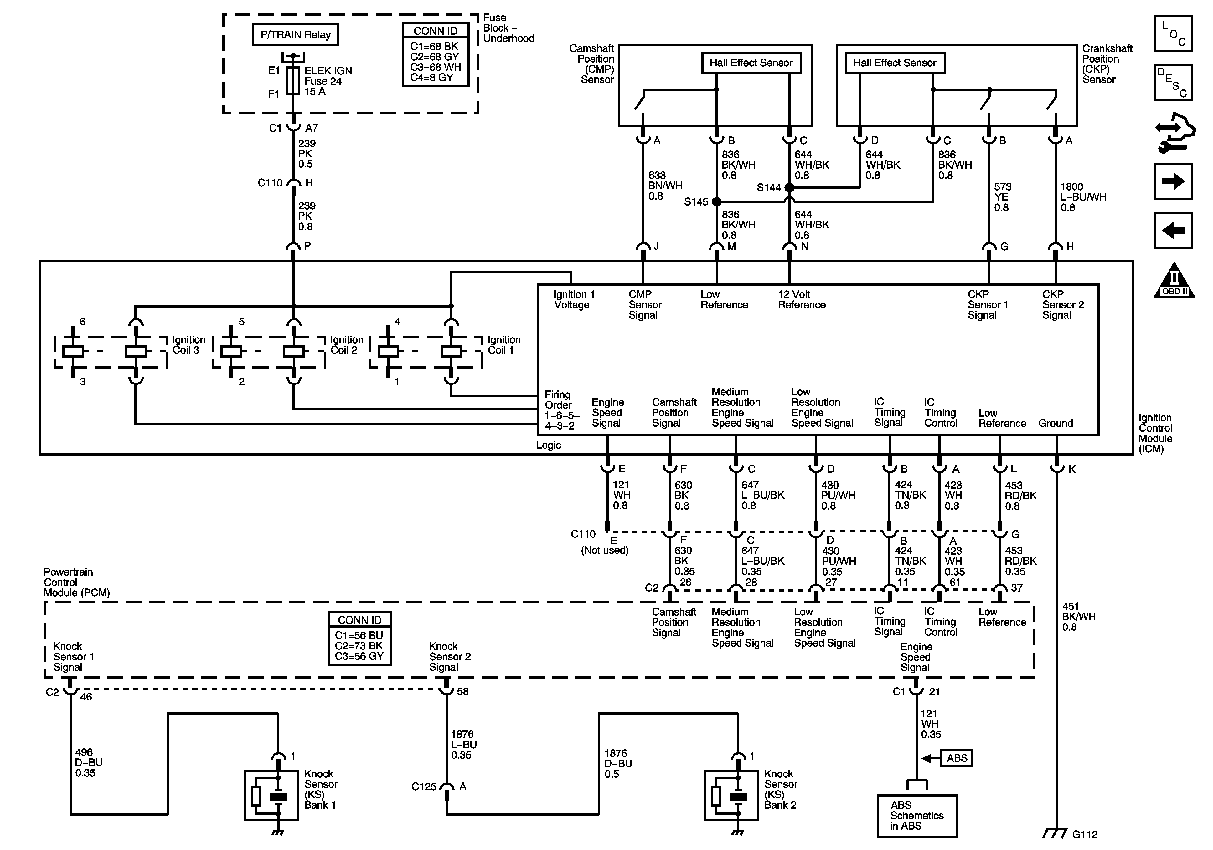
Figure 7:

Ignition Control Module


Object Number: 1653944  Size: FS
Master Electrical Component List
Electronic Ignition (EI) System Description
Control Module References
Fuel Pump Controls
Electronic Throttle Controls
Engine Controls Schematic Icons
Fuse Block Underhood Bussing
Figure 8:

Fuel Pump Controls


Object Number: 1653945  Size: FS
Master Electrical Component List
Fuel System Description
Control Module References
Fuel Injectors
Ignition Control Module
Engine Controls Schematic Icons
Fuse Block Underhood Bussing
G101, G112 (L26/L32), and G113 (L26/L32)
Power, Ground, and Gages
G302
G101, G112 (L26/L32), and G113 (L26/L32)
Figure 9:

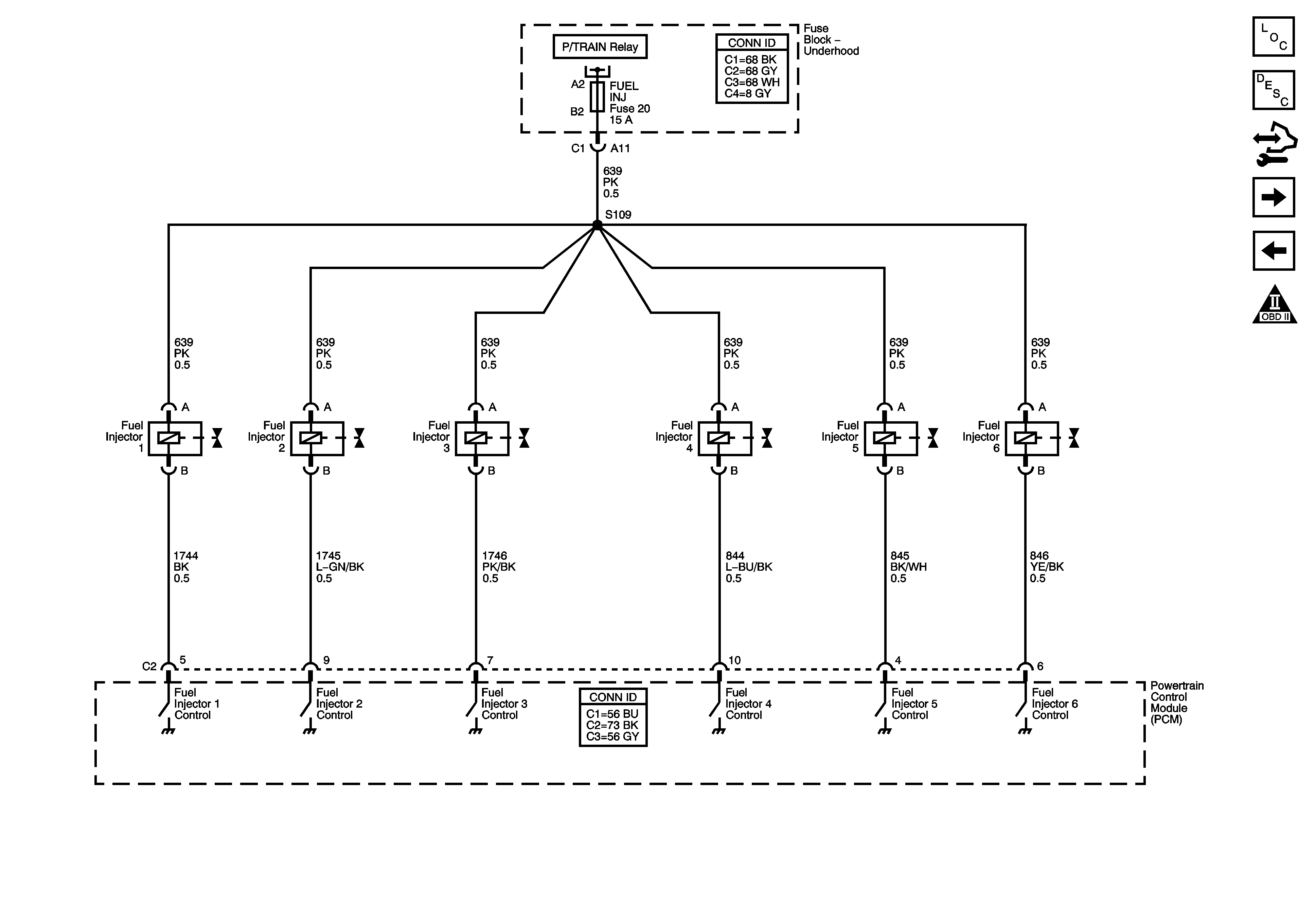
Fuel Injectors


Object Number: 1653948  Size: FS
Master Electrical Component List
Fuel System Description
Control Module References
EVAP Solenoids, FTP Sensor, and EGR Valve
Fuel Pump Controls
Engine Controls Schematic Icons
Fuse Block Underhood Bussing
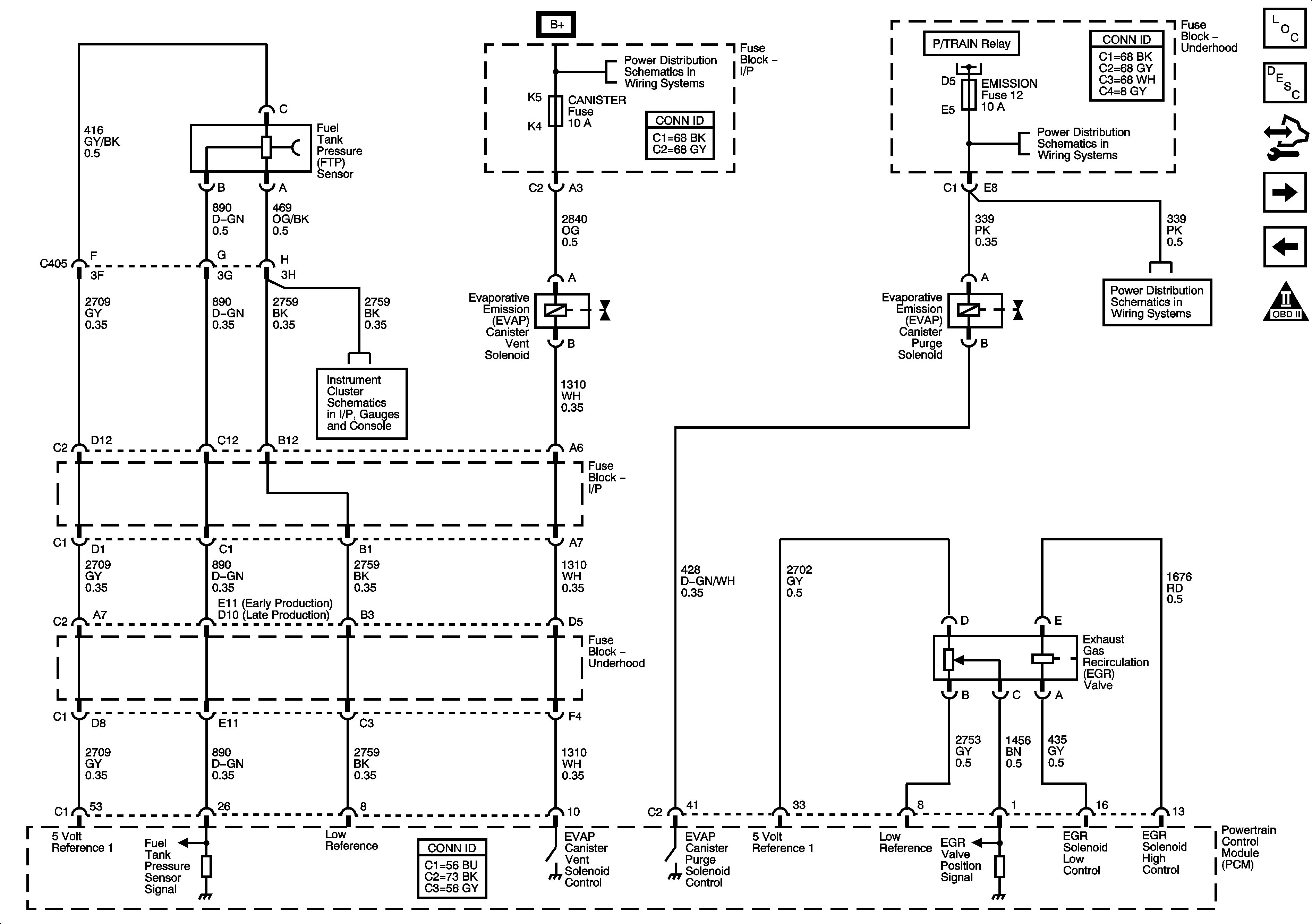
Figure 10:

EVAP Solenoids, FTP Sensor, and EGR Valve


Object Number: 1653954  Size: FS
Master Electrical Component List
Evaporative Emission Control System Description
Control Module References
Secondary Air Injection (AIR) - NU3
Fuel Injectors
Engine Controls Schematic Icons
BATT MAIN 1, PK LAMPS, DISPLAS, CHMSL/BKUP, INT LIGHT, RFA MOD, RADIO/AMP, ONSTAR/ALDL, HVAC, CANISTER Fuses AND PKLP RELAY
Power, Ground, and Gages
ETC, ELEC IGN, FUEL INJ, O2 SSR, and EMISSION Fuses
Figure 11:

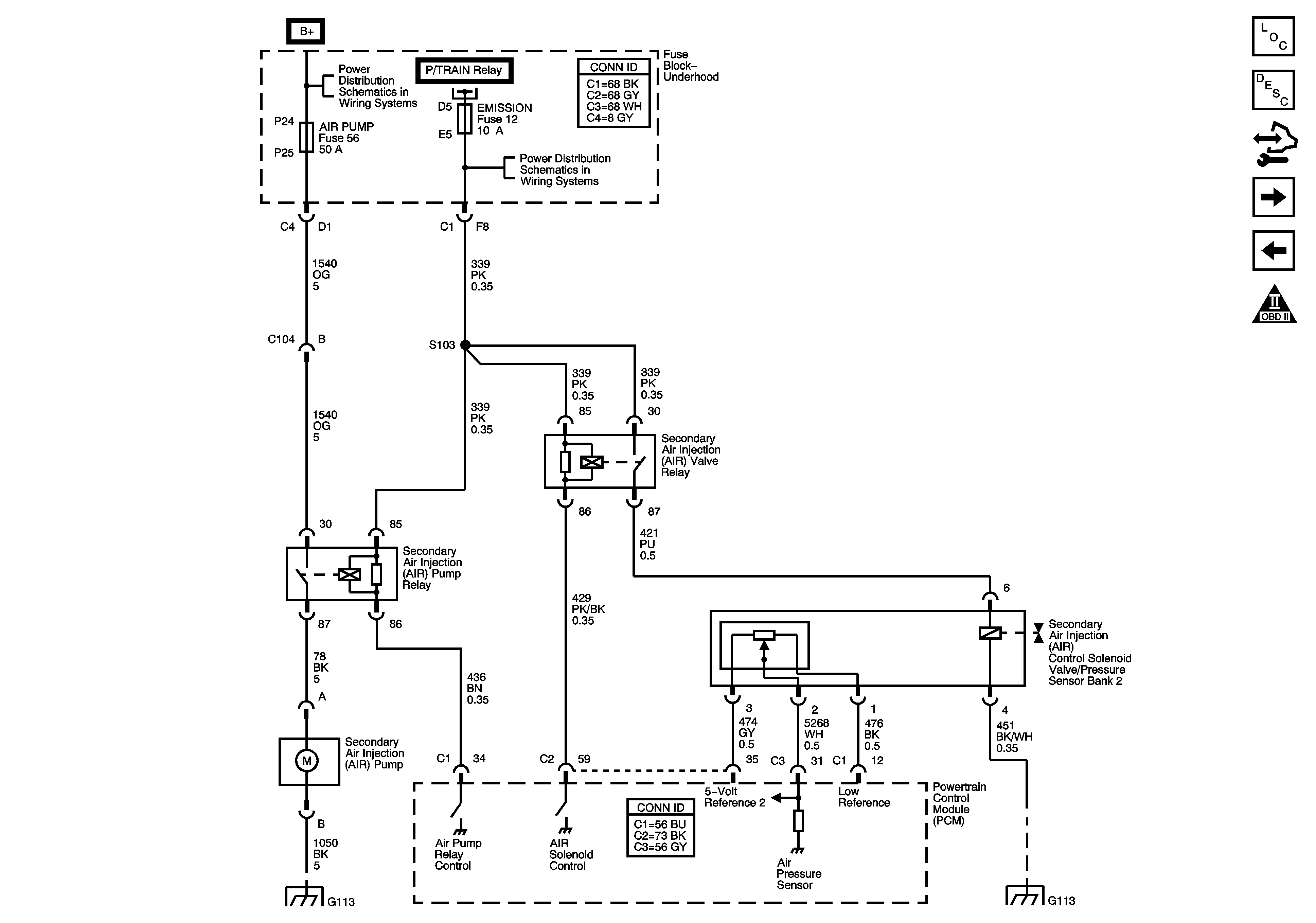
Secondary Air Injection (AIR) - NU3


Object Number: 1653966  Size: FS
Master Electrical Component List
Secondary Air Injection System Description
Control Module References
Controlled/Monitored Subsystem References
EVAP Solenoids, FTP Sensor, and EGR Valve
Engine Controls Schematic Icons
Fuse Block Underhood Bussing
ETC, ELEC IGN, FUEL INJ, O2 SSR, and EMISSION Fuses
G101, G112 (L26/L32), and G113 (L26/L32)
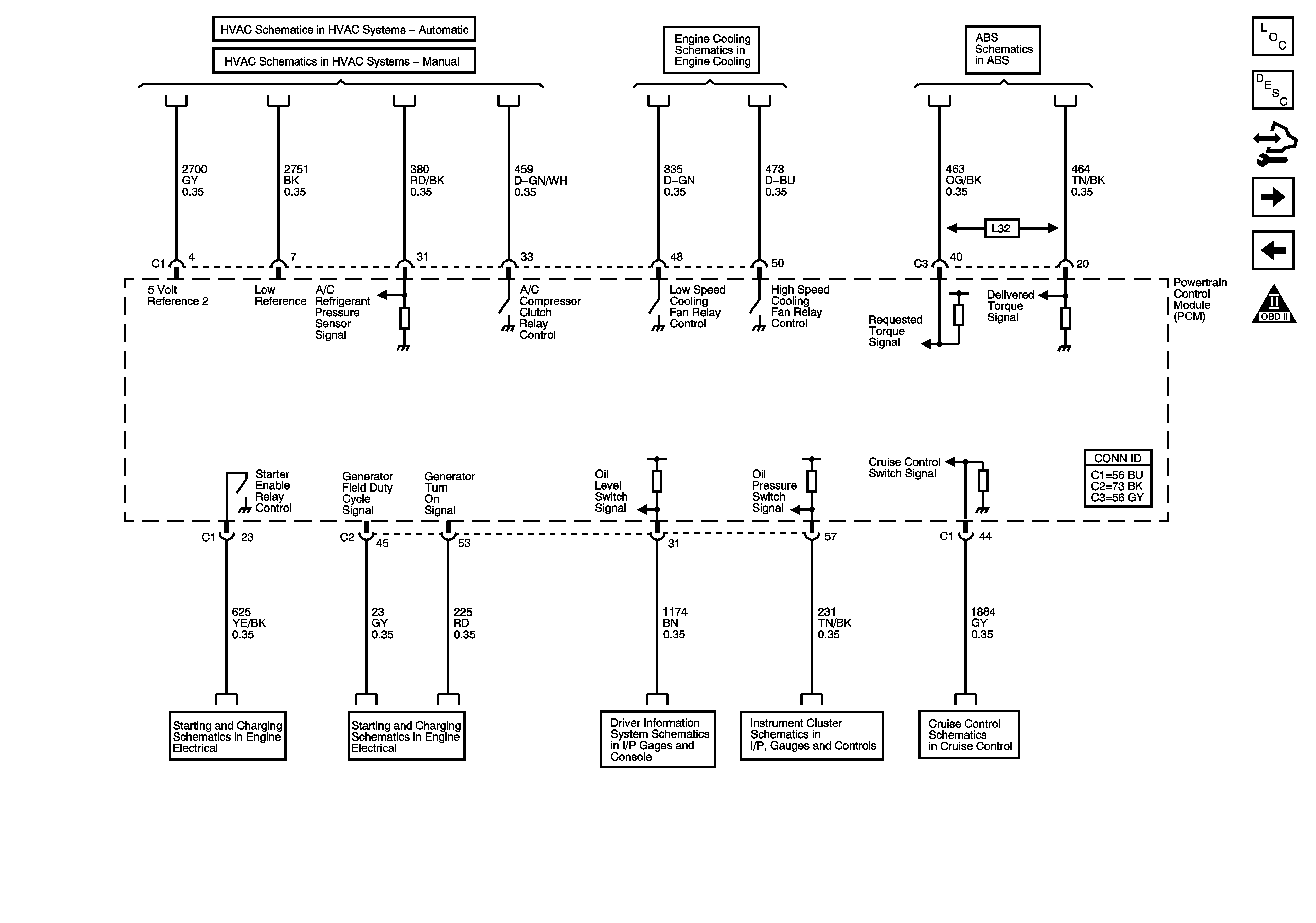
Figure 12:

Controlled/Monitored Subsystem References


Object Number: 1653956  Size: FS
Master Electrical Component List
Powertrain Control Module Description
Control Module References
Automatic Transmission Controls References
Secondary Air Injection (AIR) - NU3
Engine Controls Schematic Icons
A/C Compressor Controls
Engine Cooling Schematics
Indicator, ABS, Stability, and Traction Controls
Starting
Generator
Driver Information System
Indicators
L26, L32
Figure 13:

Automatic Transmission Controls References


Object Number: 1653960  Size: FS
Master Electrical Component List
Powertrain Control Module Description
Control Module References
Controlled/Monitored Subsystem References
Engine Controls Schematic Icons
TAP Shift Switches, StopLamp Signal, TFT Sensor and TCC Shift Solenoids
PRNDL and IMS Switch
VSS and AT Sensors, Pressure Control Solenoid Valve and TCC Release Switch