For 1990-2009 cars only
| Figure 1: |
Power, Ground and Brake Pressure Modulator Valves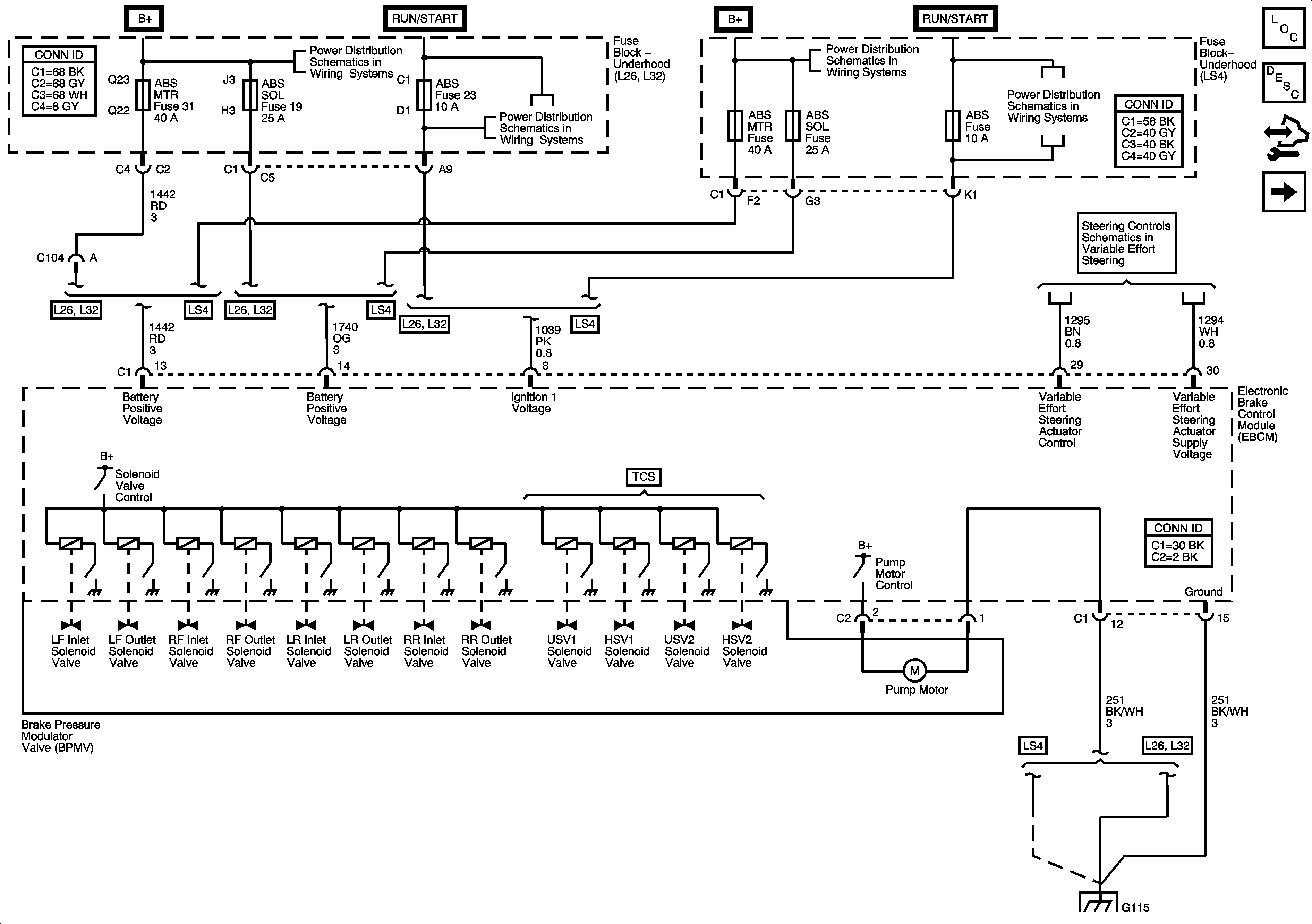
|
| Figure 2: |
Indicators, ABS, Stability and Traction Controls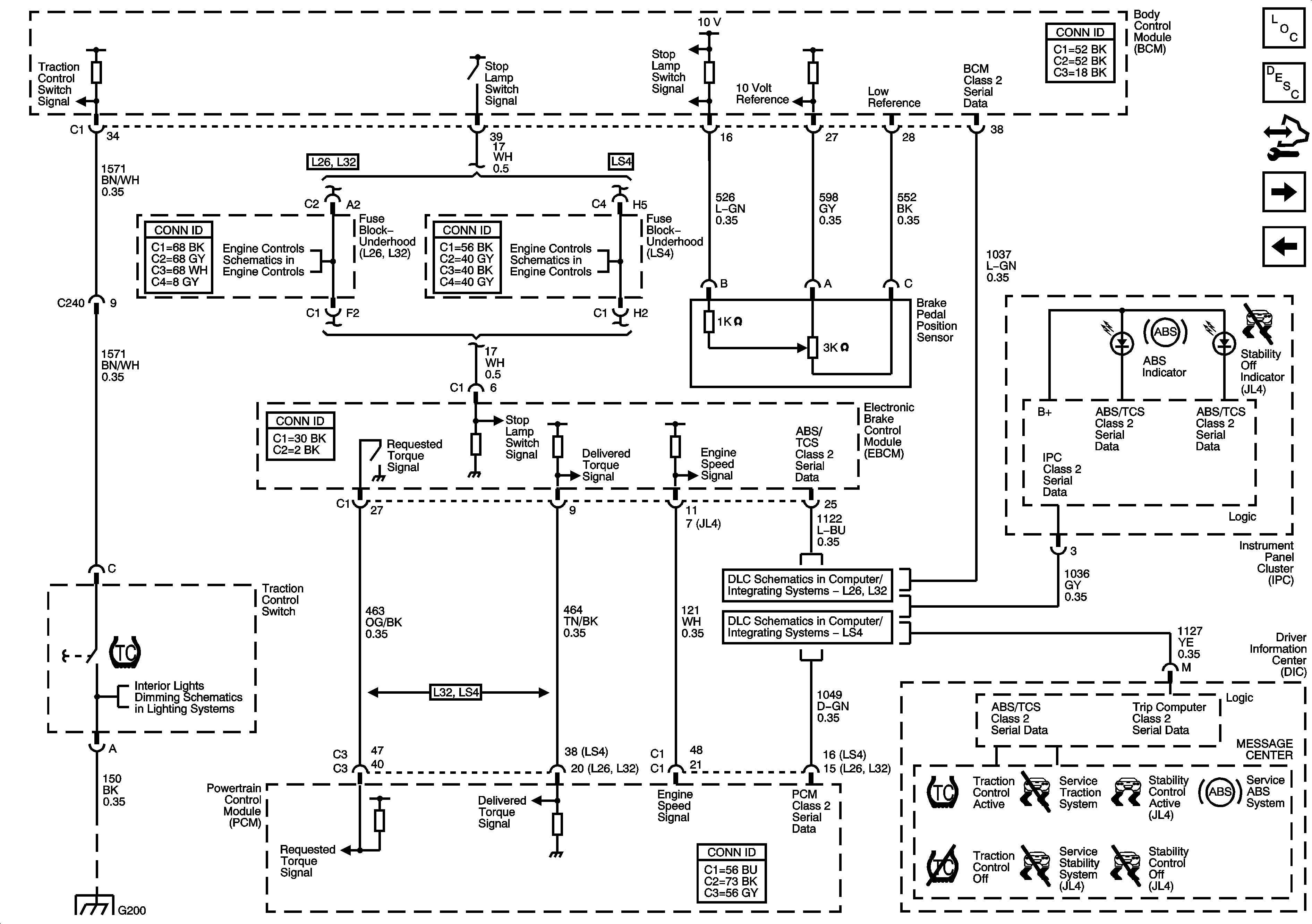
|
| Figure 3: |
Stability Control Sensors - JL4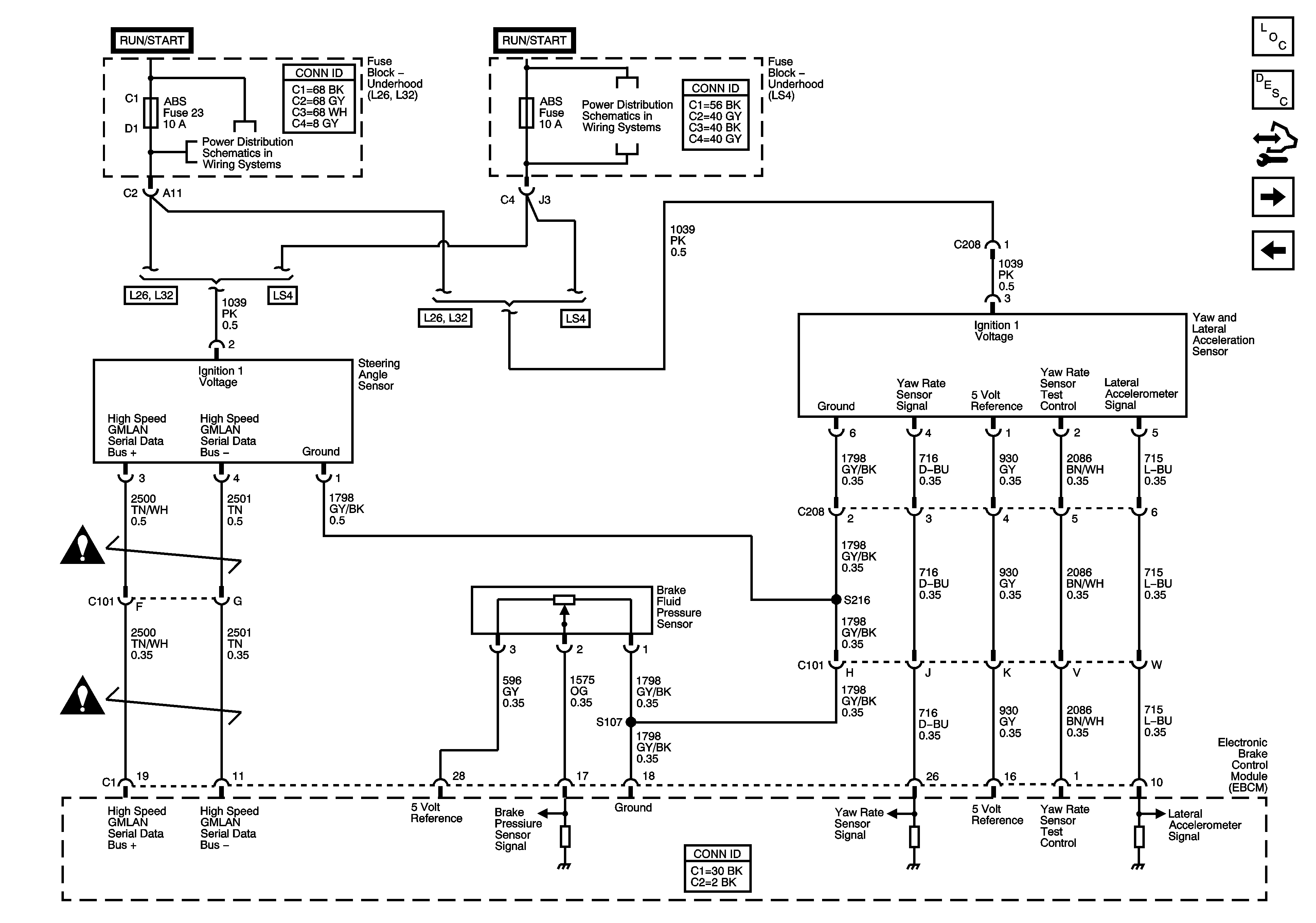
|
| Figure 4: |
Wheel Speed Sensors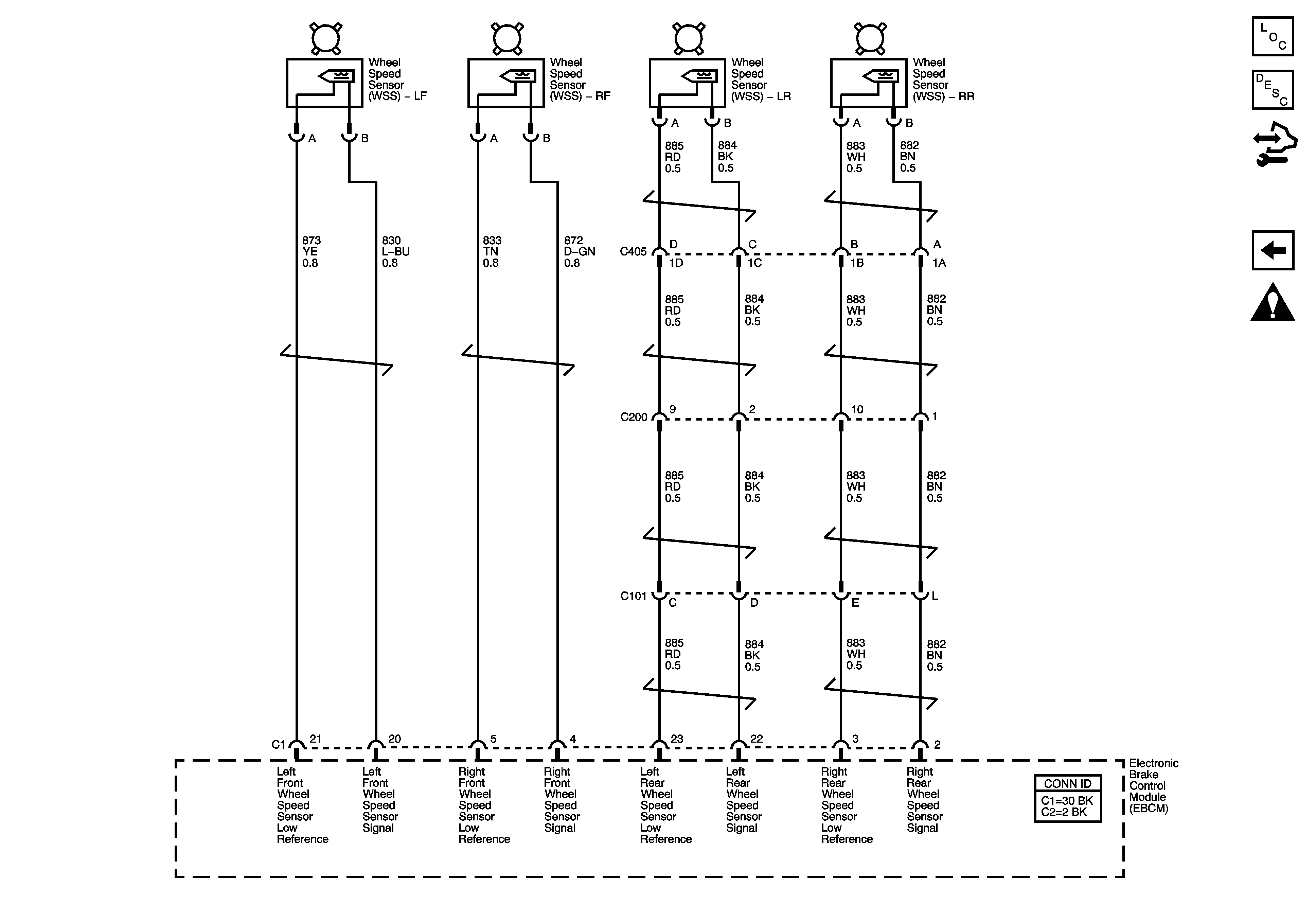
|
